Information governor
BOSCH
F 019 Z5E 695
f019z5e695
ZEXEL
105931-3583
1059313583
ISUZU
8944083573
8944083573
Rating:
Scheme ###:
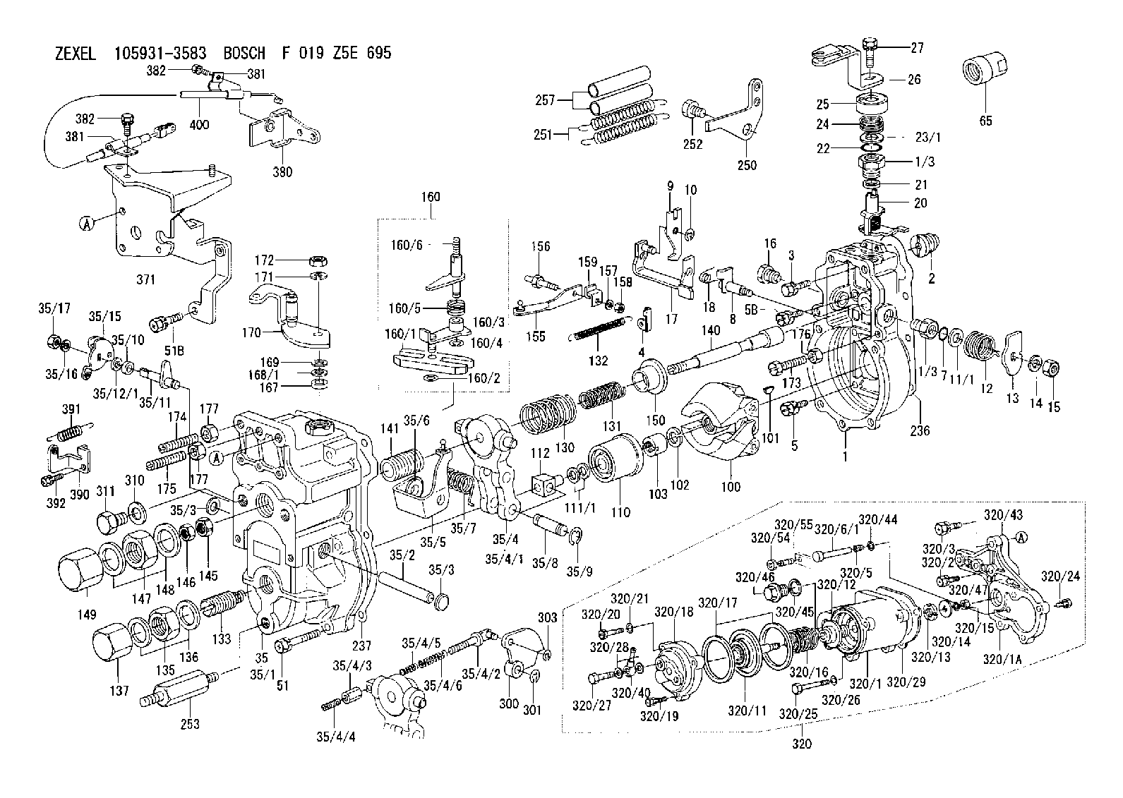
| 1. | [1] | 159200-2621 | GOVERNOR HOUSING |
| 1/3. | [2] | 154321-0400 | BUSHING |
| 1/3. | [2] | 154321-0400 | BUSHING |
| 2. | [1] | 154007-0200 | ADAPTOR |
| 3. | [1] | 020018-1840 | BLEEDER SCREW M8P1.25L18 |
| 4. | [1] | 159232-0201 | PLATE |
| 5. | [5] | 029010-6810 | BLEEDER SCREW |
| 5B. | [1] | 020106-1640 | BLEEDER SCREW M6P1.0L14 |
| 7. | [1] | 029631-0030 | O-RING &9.8W2.3 |
| 8. | [1] | 159205-2321 | LEVER SHAFT |
| 9. | [1] | 159202-0400 | CONTROL LEVER |
| 10. | [1] | 016010-0810 | LOCKING WASHER |
| 11/1. | [0] | 029311-0520 | SHIM D20.8&10.3T0.2 |
| 11/1. | [0] | 029311-0530 | SHIM D20.8&10.3T0.25 |
| 11/1. | [0] | 029311-0540 | SHIM D20.8&10.3T0.3 |
| 11/1. | [0] | 029311-0550 | SHIM D20.8&10.3T0.35 |
| 11/1. | [0] | 029311-0560 | SHIM D20.8&10.3T0.4 |
| 11/1. | [0] | 029311-0570 | SHIM D20.8&10.3T0.5 |
| 12. | [1] | 159215-0000 | COILED SPRING |
| 13. | [1] | 159242-0100 | CONTROL LEVER |
| 14. | [1] | 014110-8440 | LOCKING WASHER |
| 15. | [1] | 013020-8040 | UNION NUT M8P1.25H7 |
| 16. | [1] | 159237-0000 | CAPSULE |
| 17. | [1] | 159202-0920 | CONTROL LEVER |
| 18. | [1] | 159215-0300 | COILED SPRING |
| 20. | [1] | 159242-0220 | CONTROL LEVER |
| 21. | [1] | 159242-0600 | BUSHING |
| 22. | [1] | 029631-0030 | O-RING &9.8W2.3 |
| 23/1. | [0] | 029311-0520 | SHIM D20.8&10.3T0.2 |
| 23/1. | [0] | 029311-0530 | SHIM D20.8&10.3T0.25 |
| 23/1. | [0] | 029311-0540 | SHIM D20.8&10.3T0.3 |
| 23/1. | [0] | 029311-0550 | SHIM D20.8&10.3T0.35 |
| 23/1. | [0] | 029311-0560 | SHIM D20.8&10.3T0.4 |
| 23/1. | [0] | 029311-0570 | SHIM D20.8&10.3T0.5 |
| 24. | [1] | 159215-0000 | COILED SPRING |
| 25. | [1] | 154322-0100 | CAP |
| 26. | [1] | 159242-9520 | CONTROL LEVER |
| 27. | [1] | 020006-1640 | BLEEDER SCREW M6P1L16 4T |
| 35. | [1] | 159251-4622 | GOVERNOR COVER |
| 35/1. | [1] | 159201-3922 | GOVERNOR COVER |
| 35/2. | [1] | 159205-0400 | LEVER SHAFT |
| 35/3. | [2] | 159237-0200 | CAPSULE |
| 35/3. | [2] | 159237-0200 | CAPSULE |
| 35/4. | [1] | 159253-0120 | TENSIONING LEVER |
| 35/4/1. | [1] | 159203-0120 | TENSIONING LEVER |
| 35/4/2. | [1] | 159204-5021 | RACK |
| 35/4/3. | [1] | 159233-0300 | UNION NUT |
| 35/4/4. | [1] | 159234-0000 | FLAT-HEAD SCREW |
| 35/4/5. | [1] | 159216-0000 | COILED SPRING |
| 35/4/6. | [1] | 159216-0100 | COILED SPRING |
| 35/5. | [1] | 159203-5020 | GUIDE LEVER |
| 35/6. | [2] | 159235-5000 | BUSHING |
| 35/7. | [1] | 159215-0201 | COILED SPRING |
| 35/8. | [1] | 159231-0800 | BEARING PIN |
| 35/9. | [2] | 016010-0610 | LOCKING WASHER |
| 35/10. | [1] | 029620-8050 | PACKING RING |
| 35/11. | [1] | 159225-6222 | LEVER SHAFT |
| 35/12/1. | [0] | 029310-8280 | SHIM D16.5&8T0.1 |
| 35/12/1. | [0] | 029310-8320 | SHIM D16.5&8T0.2 |
| 35/12/1. | [0] | 029310-8340 | SHIM D16.5&8T0.3 |
| 35/12/1. | [0] | 029310-8360 | SHIM D16.5&8T0.5 |
| 35/12/1. | [0] | 029310-8660 | SHIM D16.5&8T0.6 |
| 35/12/1. | [0] | 029310-8670 | SHIM D16.5&8T1.0 |
| 35/15. | [1] | 159225-6521 | CONTROL LEVER |
| 35/16. | [1] | 014110-8440 | LOCKING WASHER |
| 35/17. | [1] | 029200-8190 | UNION NUT |
| 51. | [5] | 020106-3840 | BLEEDER SCREW |
| 51B. | [2] | 020106-4540 | BLEEDER SCREW M6P1.0L45 |
| 65. | [1] | 155404-5700 | CAP |
| 100. | [1] | 154100-9520 | FLYWEIGHT ASSEMBLY |
| 101. | [1] | 025803-1610 | WOODRUFF KEY |
| 102. | [1] | 029321-2020 | LOCKING WASHER |
| 103. | [1] | 029231-2030 | UNION NUT |
| 110. | [1] | 154123-1020 | SLIDING PIECE |
| 111/1. | [0] | 029311-0010 | SHIM D14&10.1T0.2 |
| 111/1. | [0] | 029311-0180 | SHIM D14&10.1T0.3 |
| 111/1. | [0] | 029311-0190 | SHIM D14&10.1T0.40 |
| 111/1. | [0] | 029311-0210 | SHIM D14&10.1T1 |
| 111/1. | [0] | 139410-0000 | SHIM D14.0&10.1T0.5 |
| 111/1. | [0] | 139410-0100 | SHIM D14.0&10.1T1.5 |
| 111/1. | [0] | 139410-3000 | SHIM D14&10.1T2.0 |
| 111/1. | [0] | 139410-3100 | SHIM D14&10.1T3.0 |
| 111/1. | [0] | 139410-3200 | SHIM D14&10.1T4.0 |
| 112. | [1] | 159236-0100 | TERMINAL STUD |
| 130. | [1] | 159210-3500 | GOVERNOR SPRING |
| 131. | [1] | 159211-3000 | GOVERNOR SPRING |
| 132. | [1] | 159214-0000 | COILED SPRING |
| 133. | [1] | 159212-1820 | HEADLESS SCREW |
| 135. | [1] | 139220-0200 | UNION NUT |
| 136. | [2] | 026520-2440 | GASKET D23.9&20.2T1 |
| 137. | [1] | 159248-0700 | CAP |
| 140. | [1] | 159205-0301 | LEVER SHAFT |
| 141. | [1] | 159234-5200 | GUIDE SLEEVE |
| 145. | [1] | 159233-5000 | UNION NUT |
| 146. | [1] | 023020-8040 | UNION NUT M8P1H5 |
| 147. | [1] | 139222-0200 | UNION NUT |
| 148. | [2] | 026522-2740 | GASKET D26.9&22.2T1 |
| 149. | [1] | 159237-5000 | CAP |
| 150. | [1] | 159235-5300 | SLOTTED WASHER |
| 155. | [1] | 159204-0120 | STRAP |
| 156. | [1] | 159237-0300 | BLEEDER SCREW |
| 157. | [1] | 014110-5440 | LOCKING WASHER |
| 158. | [1] | 159233-5200 | UNION NUT |
| 159. | [1] | 159242-0800 | PLATE |
| 160. | [1] | 159252-0122 | LEVER GROUP |
| 160/1. | [1] | 159202-2200 | CONTROL LEVER |
| 160/2. | [1] | 016010-0810 | LOCKING WASHER |
| 160/3. | [1] | 159202-0220 | CONTROL LEVER |
| 160/4. | [1] | 016010-0810 | LOCKING WASHER |
| 160/5. | [1] | 159215-0400 | COILED SPRING |
| 160/6. | [1] | 159205-0621 | LEVER SHAFT |
| 167. | [1] | 029621-0080 | PACKING RING |
| 168/1. | [0] | 029311-0640 | SHIM D26.0&10.2T0.95 |
| 168/1. | [0] | 029311-0650 | SHIM D26.0&10.2T0.20 |
| 168/1. | [0] | 029311-0660 | SHIM D26.0&10.2T0.25 |
| 168/1. | [0] | 029311-0670 | SHIM D26.0&10.2T0.30 |
| 168/1. | [0] | 029311-0680 | SHIM D26.0&10.2T0.35 |
| 168/1. | [0] | 029311-0690 | SHIM D26.0&10.2T0.40 |
| 168/1. | [0] | 029311-0700 | SHIM D26.0&10.2T0.50 |
| 168/1. | [0] | 139410-1400 | SHIM D26&10.2T0.7 |
| 168/1. | [0] | 139410-1500 | SHIM D26&10.2T0.9 |
| 168/1. | [0] | 139410-1600 | SHIM D26&10.2T0.8 |
| 168/1. | [0] | 139410-2700 | SHIM D26&10.2T0.6 |
| 169. | [1] | 139410-2300 | SHIM |
| 170. | [1] | 159241-1020 | CONTROL LEVER |
| 171. | [1] | 014110-8440 | LOCKING WASHER |
| 172. | [1] | 013020-8040 | UNION NUT M8P1.25H7 |
| 173. | [1] | 155615-1100 | FLAT-HEAD SCREW M6P1.0L37 |
| 174. | [1] | 154010-0100 | FLAT-HEAD SCREW |
| 175. | [1] | 154010-0100 | FLAT-HEAD SCREW |
| 176. | [1] | 029240-6010 | UNION NUT M6P1.0H5* |
| 177. | [2] | 154011-0100 | HEXAGON NUT |
| 177. | [2] | 154011-0100 | HEXAGON NUT |
| 236. | [1] | 154390-0000 | GASKET |
| 237. | [1] | 159238-3100 | GASKET |
| 250. | [1] | 159245-2820 | BRACKET |
| 251. | [2] | 159243-4800 | COILED SPRING |
| 252. | [1] | 159248-0200 | BLEEDER SCREW |
| 253. | [1] | 159248-0401 | BLEEDER SCREW |
| 257. | [2] | 154156-0500 | TUBE |
| 300. | [1] | 159207-7500 | CAM PLATE |
| 301. | [1] | 016010-0840 | LOCKING WASHER |
| 303. | [1] | 016010-0540 | LOCKING WASHER |
| 310. | [1] | 026516-2040 | GASKET D19.9&16.2T1 |
| 311. | [1] | 159237-0100 | CAPSULE |
| 320. | [1] | 154417-6821 | MANIFOLD-PRESSURE COMP. |
| 320/1. | [1] | 154408-6821 | GOVERNOR HOUSING |
| 320/1A. | [1] | 154408-2700 | SPACER BUSHING |
| 320/2. | [3] | 020106-2540 | BLEEDER SCREW M6P1L25 |
| 320/3. | [1] | 020118-3040 | BLEEDER SCREW |
| 320/5. | [1] | 159275-1400 | COILED SPRING |
| 320/6/1. | [1] | 159274-0120 | STOP PIN L125 |
| 320/6/1. | [1] | 159274-0220 | STOP PIN L127.50 |
| 320/6/1. | [1] | 159274-0320 | STOP PIN L128.00 |
| 320/6/1. | [1] | 159274-0420 | STOP PIN L127.00 |
| 320/6/1. | [1] | 159274-0520 | STOP PIN L126.00 |
| 320/6/1. | [1] | 159274-0620 | STOP PIN L129.00 |
| 320/6/1. | [1] | 159274-0720 | STOP PIN L128.50 |
| 320/6/1. | [1] | 159274-0820 | STOP PIN L125.50 |
| 320/6/1. | [1] | 159274-0920 | STOP PIN L126.50 |
| 320/6/1. | [1] | 159274-1120 | STOP PIN L119.5 |
| 320/6/1. | [1] | 159274-1220 | STOP PIN L120 |
| 320/6/1. | [1] | 159274-1320 | STOP PIN L120.5 |
| 320/6/1. | [1] | 159274-1420 | STOP PIN L121 |
| 320/6/1. | [1] | 159274-1520 | STOP PIN L121.5 |
| 320/6/1. | [1] | 159274-1620 | STOP PIN L122 |
| 320/6/1. | [1] | 159274-1720 | STOP PIN L122.5 |
| 320/6/1. | [1] | 159274-1820 | STOP PIN L123 |
| 320/6/1. | [1] | 159274-1920 | STOP PIN L123.5 |
| 320/6/1. | [1] | 159274-4220 | STOP PIN L129.5 |
| 320/6/1. | [1] | 159274-4320 | STOP PIN L130 |
| 320/6/1. | [1] | 159274-4420 | STOP PIN L130.5 |
| 320/6/1. | [1] | 159274-4520 | STOP PIN L131 |
| 320/6/1. | [1] | 159274-4620 | STOP PIN L131.5 |
| 320/6/1. | [1] | 159274-4720 | STOP PIN L132 |
| 320/6/1. | [1] | 159274-4820 | STOP PIN L132.5 |
| 320/6/1. | [1] | 159274-4920 | STOP PIN L133 |
| 320/6/1. | [1] | 159274-5020 | STOP PIN L133.5 |
| 320/11. | [1] | 154400-0820 | DIAPHRAGM |
| 320/12. | [1] | 154406-5300 | GUIDE SLEEVE |
| 320/13. | [1] | 154406-5400 | UNION NUT |
| 320/14. | [1] | 154406-5500 | SLOTTED WASHER |
| 320/15. | [1] | 013030-6040 | UNION NUT M6P1H3.6 |
| 320/16. | [1] | 154403-8300 | COILED SPRING |
| 320/17. | [2] | 154413-2600 | GASKET |
| 320/18. | [1] | 154404-4920 | COVER |
| 320/19. | [2] | 020106-2040 | BLEEDER SCREW M6P1L20 |
| 320/20. | [1] | 139006-7000 | BLEEDER SCREW |
| 320/21. | [1] | 014110-6440 | LOCKING WASHER |
| 320/24. | [3] | 020106-2040 | BLEEDER SCREW M6P1L20 |
| 320/25. | [1] | 139006-1300 | BLEEDER SCREW M6P1L76 |
| 320/26. | [1] | 029320-6010 | LOCKING WASHER |
| 320/27. | [1] | 029731-0180 | EYE BOLT |
| 320/28. | [2] | 026510-1340 | GASKET D13.4&10.2T1 |
| 320/29. | [1] | 154413-2800 | GASKET |
| 320/40. | [1] | 154412-7920 | JOINT CONNECTION |
| 320/43. | [1] | 154390-2100 | GASKET |
| 320/44. | [1] | 014010-5140 | PLAIN WASHER D12&5.5T0.8 |
| 320/45. | [1] | 029331-8040 | GASKET |
| 320/46. | [1] | 154406-5800 | FLAT-HEAD SCREW |
| 320/47. | [1] | 014110-6440 | LOCKING WASHER |
| 320/54. | [1] | 013030-6040 | UNION NUT M6P1H3.6 |
| 320/55. | [1] | 154404-4800 | FLAT-HEAD SCREW |
| 371. | [1] | 159226-2521 | BRACKET |
| 380. | [1] | 159225-8500 | BRACKET |
| 381. | [2] | 159225-7201 | CLAMPING BAND |
| 381. | [2] | 159225-7201 | CLAMPING BAND |
| 382. | [2] | 020146-1240 | BLEEDER SCREW M6P1.0L12 |
| 382. | [2] | 020146-1240 | BLEEDER SCREW M6P1.0L12 |
| 390. | [1] | 159225-6720 | BRACKET |
| 391. | [1] | 159225-6800 | COILED SPRING |
| 392. | [1] | 020106-1240 | BLEEDER SCREW M6P1.0L12 |
| 400. | [1] | 159225-7301 | WIRE |
Include in #1:
101401-0661
as GOVERNOR
Cross reference number
Zexel num
Bosch num
Firm num
Name
105931-3583
8944083573 ISUZU
GOVERNOR
K 14JK MECHANICAL GOVERNOR GOV RLD GOV
K 14JK MECHANICAL GOVERNOR GOV RLD GOV
Information:
1. Disconnect the fuel ratio control sensing line (1). Remove the sensing line clamp bolt (2).2. Disconnect the air compressor water return line (6). 3. Remove the cylinder head air inlet line (3).4. Remove the retaining bolts (4) and the fan drive mounting bracket (5).5. Remove the cylinder head retaining bolts. Attach a hoist and remove the cylinder head assembly - weight 164 lbs. (74,4 kg).Install Cylinder Head
1. Thoroughly clean the sealing surfaces of the cylinder head and cylinder block. Position a new head gasket on the engine and install the cylinder head.2. Install the push rods and rocker shaft assembly.3. Coat the threads of the cylinder head retaining bolts with 4S9416 Anti-Seize Compound. Install bolts and washers, and tighten them in the following sequence: 1 - Tighten all numbered bolts in numerical order to 115 lb. ft. (15,9 mkg).2 - Retighten all numbered bolts in numerical order to 175 5 lb. ft. (24,2 0,7 mkg).3 - Finally, retighten all numbered bolts (hand torque only) in numerical order to 175 5 lb. ft. (24,2 0,7 mkg).4 - Tighten all lettered bolts in alphabetical order to 22 lb. ft. (3,0 mkg).5 - Retighten all lettered bolts in alphabetical order to 32 5 lb. ft. (4,4 0,7 mkg).6 - Finally, retighten all lettered bolts (hand torque only) in alphabetical order to 32 5 lb. ft. (4,4 0,7 mkg).4. Adjust the inlet and exhaust valve clearance as covered in INSTALL ROCKER SHAFT ASSEMBLY AND PUSH RODS.5. Connect the air compressor water return line.6. Connect the fuel ratio control sensing line and install the sensing line clamp bolt.7. Install the fan drive mounting bracket and retaining bolts.concluding steps: a) install water temperature regulatorb) install valve coverc) install precombustion chambersd) install exhaust manifold
1. Thoroughly clean the sealing surfaces of the cylinder head and cylinder block. Position a new head gasket on the engine and install the cylinder head.2. Install the push rods and rocker shaft assembly.3. Coat the threads of the cylinder head retaining bolts with 4S9416 Anti-Seize Compound. Install bolts and washers, and tighten them in the following sequence: 1 - Tighten all numbered bolts in numerical order to 115 lb. ft. (15,9 mkg).2 - Retighten all numbered bolts in numerical order to 175 5 lb. ft. (24,2 0,7 mkg).3 - Finally, retighten all numbered bolts (hand torque only) in numerical order to 175 5 lb. ft. (24,2 0,7 mkg).4 - Tighten all lettered bolts in alphabetical order to 22 lb. ft. (3,0 mkg).5 - Retighten all lettered bolts in alphabetical order to 32 5 lb. ft. (4,4 0,7 mkg).6 - Finally, retighten all lettered bolts (hand torque only) in alphabetical order to 32 5 lb. ft. (4,4 0,7 mkg).4. Adjust the inlet and exhaust valve clearance as covered in INSTALL ROCKER SHAFT ASSEMBLY AND PUSH RODS.5. Connect the air compressor water return line.6. Connect the fuel ratio control sensing line and install the sensing line clamp bolt.7. Install the fan drive mounting bracket and retaining bolts.concluding steps: a) install water temperature regulatorb) install valve coverc) install precombustion chambersd) install exhaust manifold