Information governor
BOSCH
F 019 Z2F 057
f019z2f057
ZEXEL
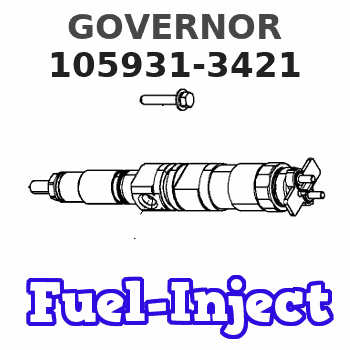
105931-3421
1059313421
ISUZU
8944067451
8944067451
Rating:
Scheme ###:
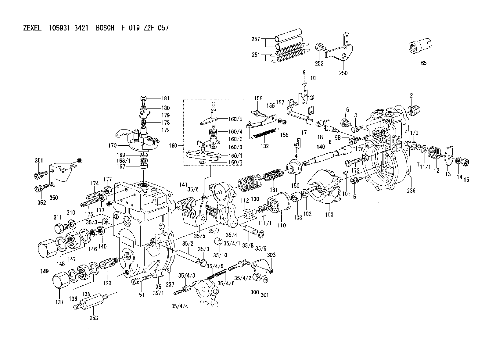
| 1. | [1] | 159200-1720 | GOVERNOR HOUSING |
| 1/3. | [1] | 154321-0400 | BUSHING |
| 2. | [1] | 154007-0200 | ADAPTOR |
| 3. | [1] | 020018-1840 | BLEEDER SCREW M8P1.25L18 |
| 4. | [1] | 159232-2820 | PLATE |
| 5. | [5] | 029010-6810 | BLEEDER SCREW |
| 5B. | [1] | 020106-1640 | BLEEDER SCREW M6P1.0L14 |
| 7. | [1] | 016530-1010 | O-RING |
| 8. | [1] | 159205-2321 | LEVER SHAFT |
| 9. | [1] | 159202-0400 | CONTROL LEVER |
| 10. | [1] | 016010-0810 | LOCKING WASHER |
| 11/1. | [0] | 029311-0520 | SHIM D20.8&10.3T0.2 |
| 11/1. | [0] | 029311-0530 | SHIM D20.8&10.3T0.25 |
| 11/1. | [0] | 029311-0540 | SHIM D20.8&10.3T0.3 |
| 11/1. | [0] | 029311-0550 | SHIM D20.8&10.3T0.35 |
| 11/1. | [0] | 029311-0560 | SHIM D20.8&10.3T0.4 |
| 11/1. | [0] | 029311-0570 | SHIM D20.8&10.3T0.5 |
| 12. | [1] | 159215-0000 | COILED SPRING |
| 13. | [1] | 159242-6601 | CONTROL LEVER |
| 14. | [1] | 014110-8440 | LOCKING WASHER |
| 15. | [1] | 013020-8040 | UNION NUT M8P1.25H7 |
| 16. | [1] | 159237-0000 | CAPSULE |
| 17. | [1] | 159202-0320 | CONTROL LEVER |
| 18. | [1] | 159215-0300 | COILED SPRING |
| 35. | [1] | 159251-2520 | GOVERNOR COVER |
| 35/1. | [1] | 159201-2520 | GOVERNOR COVER |
| 35/2. | [1] | 159205-0400 | LEVER SHAFT |
| 35/3. | [2] | 159237-0200 | CAPSULE |
| 35/3. | [2] | 159237-0200 | CAPSULE |
| 35/4. | [1] | 159253-0120 | TENSIONING LEVER |
| 35/4/1. | [1] | 159203-0120 | TENSIONING LEVER |
| 35/4/2. | [1] | 159204-5021 | RACK |
| 35/4/3. | [1] | 159233-0300 | UNION NUT |
| 35/4/4. | [1] | 159234-0000 | FLAT-HEAD SCREW |
| 35/4/5. | [1] | 159216-0000 | COILED SPRING |
| 35/4/6. | [1] | 159216-0100 | COILED SPRING |
| 35/5. | [1] | 159203-5020 | GUIDE LEVER |
| 35/6. | [2] | 159235-5000 | BUSHING |
| 35/7. | [1] | 159215-0201 | COILED SPRING |
| 35/8. | [1] | 159231-0800 | BEARING PIN |
| 35/9. | [2] | 016010-0610 | LOCKING WASHER |
| 35/10. | [1] | 159238-1801 | BUSHING |
| 51. | [7] | 020106-3840 | BLEEDER SCREW |
| 65. | [1] | 155404-3700 | CAP |
| 100. | [1] | 154101-0820 | FLYWEIGHT ASSEMBLY |
| 101. | [1] | 025803-1610 | WOODRUFF KEY |
| 102. | [1] | 029321-2020 | LOCKING WASHER |
| 103. | [1] | 029231-2030 | UNION NUT |
| 110. | [1] | 154123-2320 | SLIDING PIECE |
| 111/1. | [0] | 029311-0010 | SHIM D14&10.1T0.2 |
| 111/1. | [0] | 029311-0180 | SHIM D14&10.1T0.3 |
| 111/1. | [0] | 029311-0190 | SHIM D14&10.1T0.40 |
| 111/1. | [0] | 029311-0210 | SHIM D14&10.1T1 |
| 111/1. | [0] | 139410-0000 | SHIM D14.0&10.1T0.5 |
| 111/1. | [0] | 139410-0100 | SHIM D14.0&10.1T1.5 |
| 111/1. | [0] | 139410-3000 | SHIM D14&10.1T2.0 |
| 111/1. | [0] | 139410-3100 | SHIM D14&10.1T3.0 |
| 111/1. | [0] | 139410-3200 | SHIM D14&10.1T4.0 |
| 112. | [1] | 159236-0100 | TERMINAL STUD |
| 130. | [1] | 159210-5300 | GOVERNOR SPRING |
| 131. | [1] | 159211-3800 | GOVERNOR SPRING |
| 132. | [1] | 159214-0100 | COILED SPRING |
| 133. | [1] | 159212-1220 | HEADLESS SCREW |
| 135. | [1] | 139220-0200 | UNION NUT |
| 136. | [2] | 026520-2440 | GASKET D23.9&20.2T1 |
| 137. | [1] | 159248-0700 | CAP |
| 140. | [1] | 159205-1801 | LEVER SHAFT |
| 141. | [1] | 159234-5200 | GUIDE SLEEVE |
| 145. | [1] | 159233-5000 | UNION NUT |
| 146. | [1] | 023020-8040 | UNION NUT M8P1H5 |
| 147. | [1] | 139222-0200 | UNION NUT |
| 148. | [2] | 026522-2740 | GASKET D26.9&22.2T1 |
| 149. | [1] | 159237-5000 | CAP |
| 150. | [1] | 159235-5300 | SLOTTED WASHER |
| 155. | [1] | 159204-7920 | STRAP |
| 156. | [1] | 159233-0200 | BLEEDER SCREW |
| 157. | [1] | 014110-5440 | LOCKING WASHER |
| 158. | [1] | 159233-5200 | UNION NUT |
| 160. | [1] | 159252-0521 | LEVER GROUP |
| 160/1. | [1] | 159202-1400 | CONTROL LEVER |
| 160/2. | [1] | 159202-1520 | CONTROL LEVER |
| 160/3. | [1] | 016010-0610 | LOCKING WASHER |
| 160/4. | [1] | 159215-1300 | COILED SPRING |
| 160/5. | [1] | 159205-1721 | LEVER SHAFT |
| 160/6. | [1] | 016010-0810 | LOCKING WASHER |
| 167. | [1] | 029621-0080 | PACKING RING |
| 168/1. | [0] | 029311-0640 | SHIM D26.0&10.2T0.95 |
| 168/1. | [0] | 029311-0650 | SHIM D26.0&10.2T0.20 |
| 168/1. | [0] | 029311-0660 | SHIM D26.0&10.2T0.25 |
| 168/1. | [0] | 029311-0670 | SHIM D26.0&10.2T0.30 |
| 168/1. | [0] | 029311-0680 | SHIM D26.0&10.2T0.35 |
| 168/1. | [0] | 029311-0690 | SHIM D26.0&10.2T0.40 |
| 168/1. | [0] | 029311-0700 | SHIM D26.0&10.2T0.50 |
| 168/1. | [0] | 139410-1400 | SHIM D26&10.2T0.7 |
| 168/1. | [0] | 139410-1500 | SHIM D26&10.2T0.9 |
| 168/1. | [0] | 139410-1600 | SHIM D26&10.2T0.8 |
| 168/1. | [0] | 139410-2700 | SHIM D26&10.2T0.6 |
| 169. | [1] | 139410-2300 | SHIM |
| 170. | [1] | 159241-1720 | CONTROL LEVER |
| 172. | [1] | 159248-2800 | UNION NUT |
| 173. | [1] | 159233-0400 | BLEEDER SCREW |
| 174. | [1] | 154010-8300 | FLAT-HEAD SCREW |
| 175. | [1] | 154010-8300 | FLAT-HEAD SCREW |
| 176. | [1] | 029240-6010 | UNION NUT M6P1.0H5* |
| 177. | [2] | 154011-0100 | HEXAGON NUT |
| 177. | [2] | 154011-0100 | HEXAGON NUT |
| 178. | [1] | 159248-2100 | COILED SPRING |
| 179. | [1] | 159241-3400 | PLATE |
| 180. | [1] | 014020-8140 | PLAIN WASHER D16&8.5T1.2 |
| 181. | [1] | 029010-8140 | BLEEDER SCREW |
| 236. | [1] | 154390-0000 | GASKET |
| 237. | [1] | 154390-1100 | GASKET |
| 250. | [1] | 159225-2020 | BRACKET |
| 251. | [2] | 159243-4900 | COILED SPRING |
| 252. | [1] | 159248-0200 | BLEEDER SCREW |
| 253. | [1] | 159248-0401 | BLEEDER SCREW |
| 257. | [2] | 154156-1800 | TUBE |
| 300. | [1] | 159208-2200 | CAM PLATE |
| 301. | [1] | 016010-0840 | LOCKING WASHER |
| 303. | [1] | 016010-0540 | LOCKING WASHER |
| 310. | [1] | 026516-2040 | GASKET D19.9&16.2T1 |
| 311. | [1] | 159237-0100 | CAPSULE |
| 350. | [1] | 159245-7300 | BRACKET |
| 351. | [1] | 020118-2040 | BLEEDER SCREW M8P1.25L20 |
| 352. | [1] | 020106-1040 | BLEEDER SCREW M6P1L12 |
Include in #1:
101491-0420
as GOVERNOR
Cross reference number
Zexel num
Bosch num
Firm num
Name
105931-3421
F 019 Z2F 057
8944067451 ISUZU
GOVERNOR
* K
* K
Information:
Connecting Rod
Use the 2H6782 Connecting Rod Boring Machine to recondition connecting rods and to check for connecting rod distortion. The 5P2009 Rework Group is available for the 2H6782 Connecting Rod Boring Machine. To install the rework group see Special Instruction GMG02394.Press a new piston pin bushing into the connecting rod. Assemble new rod bearings and the expansion sleeve. Tighten rod bolt nuts in the following step sequence.1. Put crankcase oil on bolt threads and seating faces of cap and nut.2. Tighten both nuts to 30 3 lb. ft. (40 4 N m).3. Put a mark on each nut and cap.4. Tighten each nut 60° from the mark.Clean spindle and slide the expansion sleeve and connecting rod into place. Install and tighten nut hand tight.Adjust the carrier to the distance between center of the bores, [center-to-center distance is 7.900 .001 in. (200.66 0.03 mm)]. Position the locating rods .25 in. (6.4 mm) from the connecting rod. Install front bushing in bracket and insert locating arbor through front bushing. Slide the centering sleeve over the end of the locating arbor. Slide the locating arbor through the rear bushing, centering sleeve, and into the connecting rod. Tighten knobs until locating rods lightly contact the connecting rod. Lock the locating rods and carrier.To check connecting rod distortion, slide locating arbor in and out of rear bushing. If the locating arbor does not slide freely, recheck horizontal location. If the locating arbor still binds, loosen the carrier clamp and raise or lower the carrier until the locating arbor slides freely. Read the vernier scale and note the variation from the nominal dimension. If the variation exceeds .010 in. (0.25 mm) the rod is distorted and should be replaced. Mark replacement rods for cylinder identification on bearing tab slot side of rod and cap.With the center-to-center distance set to the nominal dimension, set tool in boring bar and insert the boring bar and front bushing. Connect boring bar to the feed mechanism and engage the feed lever. Install the hand crank or an electric drill and flexible adapter and bore the bushing. Use a slow feed rate. Check the bore size. The size is 1.5010 .0003 in. (48.125 0.008 mm). A 5P2050 Connecting Rod Checking Fixture is available for checking connecting rods. For instructions for the use of the checking fixture see Special Instruction SMHS7366.Install connecting rod into piston with boss on rod on same side as crater in piston crown.
CONNECTING ROD AND PISTONWhen installing connecting rod and piston assemblies, inspect the threads of the rod bolts and nuts for damage. The contact surface of the nuts must be flat and free from damage. Damaged parts must be replaced.
Have questions with 105931-3421?
Group cross 105931-3421 ZEXEL
Isuzu
Mitsubishi
Isuzu
105931-3421
F 019 Z2F 057
8944067451
GOVERNOR