Information governor
BOSCH
9 420 610 311
9420610311
ZEXEL
105931-2641
1059312641
MITSUBISHI
ME741564
me741564
Rating:
Scheme ###:
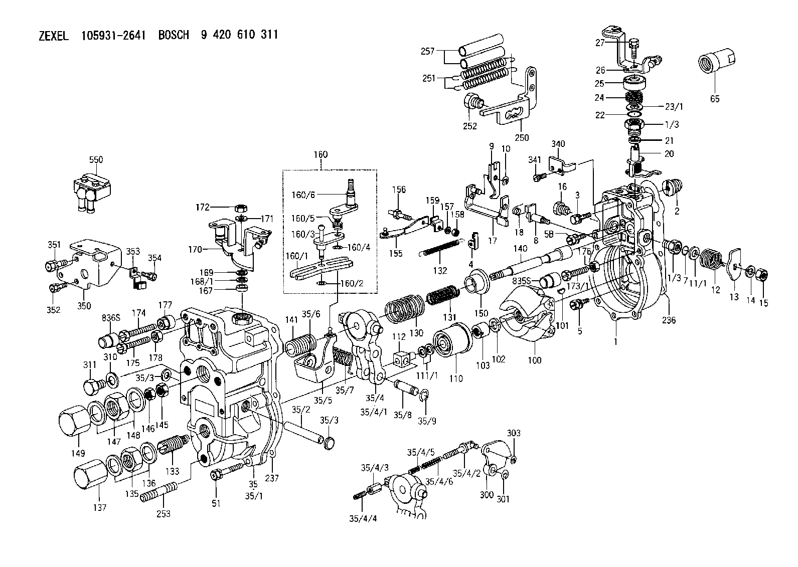
| 1. | [1] | 159200-2320 | GOVERNOR HOUSING |
| 1/3. | [2] | 154321-2600 | BUSHING |
| 1/3. | [2] | 154321-2600 | BUSHING |
| 2. | [1] | 154007-0200 | ADAPTOR |
| 3. | [1] | 020018-1840 | BLEEDER SCREW |
| 4. | [1] | 159232-0201 | PLATE |
| 5. | [5] | 029010-6810 | BLEEDER SCREW |
| 5B. | [1] | 020106-1640 | BLEEDER SCREW |
| 7. | [1] | 029631-0030 | O-RING |
| 8. | [1] | 159205-2321 | LEVER SHAFT |
| 9. | [1] | 159202-0400 | CONTROL LEVER |
| 10. | [1] | 016010-0810 | LOCKING WASHER |
| 11/1. | [0] | 029311-0520 | SHIM D20.8&10.3T0.2 |
| 11/1. | [0] | 029311-0530 | SHIM D20.8&10.3T0.25 |
| 11/1. | [0] | 029311-0540 | SHIM D20.8&10.3T0.3 |
| 11/1. | [0] | 029311-0550 | SHIM D20.8&10.3T0.35 |
| 11/1. | [0] | 029311-0560 | SHIM D20.8&10.3T0.4 |
| 11/1. | [0] | 029311-0570 | SHIM D20.8&10.3T0.5 |
| 12. | [1] | 159215-0000 | COILED SPRING |
| 13. | [1] | 159242-0100 | CONTROL LEVER |
| 14. | [1] | 014110-8440 | LOCKING WASHER D15.4&8.2T2 |
| 15. | [1] | 013020-8040 | UNION NUT |
| 16. | [1] | 159237-0000 | CAPSULE |
| 17. | [1] | 159202-0320 | CONTROL LEVER |
| 18. | [1] | 159215-0300 | COILED SPRING |
| 20. | [1] | 159242-0220 | CONTROL LEVER |
| 21. | [1] | 159242-0600 | BUSHING |
| 22. | [1] | 016530-1010 | O-RING |
| 23/1. | [0] | 029311-0520 | SHIM D20.8&10.3T0.2 |
| 23/1. | [0] | 029311-0530 | SHIM D20.8&10.3T0.25 |
| 23/1. | [0] | 029311-0540 | SHIM D20.8&10.3T0.3 |
| 23/1. | [0] | 029311-0550 | SHIM D20.8&10.3T0.35 |
| 23/1. | [0] | 029311-0560 | SHIM D20.8&10.3T0.4 |
| 23/1. | [0] | 029311-0570 | SHIM D20.8&10.3T0.5 |
| 24. | [1] | 159215-2900 | COILED SPRING |
| 25. | [1] | 154322-0100 | CAP |
| 26. | [1] | 159242-6520 | CONTROL LEVER |
| 27. | [1] | 020006-1640 | BLEEDER SCREW |
| 35. | [1] | 159251-1120 | GOVERNOR COVER |
| 35/1. | [1] | 159201-1420 | GOVERNOR COVER |
| 35/2. | [1] | 159205-0400 | LEVER SHAFT |
| 35/3. | [2] | 159237-0200 | CAPSULE |
| 35/3. | [2] | 159237-0200 | CAPSULE |
| 35/4. | [1] | 159253-0120 | TENSIONING LEVER |
| 35/4/1. | [1] | 159203-0120 | TENSIONING LEVER |
| 35/4/2. | [1] | 159204-5021 | RACK |
| 35/4/3. | [1] | 159233-0300 | UNION NUT |
| 35/4/4. | [1] | 159234-0000 | FLAT-HEAD SCREW |
| 35/4/5. | [1] | 159216-0000 | COILED SPRING |
| 35/4/6. | [1] | 159216-0100 | COILED SPRING |
| 35/5. | [1] | 159203-5020 | GUIDE LEVER |
| 35/6. | [2] | 159235-5000 | BUSHING |
| 35/7. | [1] | 159215-0201 | COILED SPRING |
| 35/8. | [1] | 159231-0800 | BEARING PIN |
| 35/9. | [2] | 016010-0610 | LOCKING WASHER |
| 51. | [7] | 020106-3840 | BLEEDER SCREW |
| 65. | [1] | 154050-1720 | STOPPING DEVICE |
| 100. | [1] | 154100-9520 | FLYWEIGHT ASSEMBLY |
| 101. | [1] | 025803-1610 | WOODRUFF KEY 16 MM |
| 102. | [1] | 029321-2020 | LOCKING WASHER |
| 103. | [1] | 029231-2030 | UNION NUT |
| 110. | [1] | 154123-1020 | SLIDING PIECE |
| 111/1. | [0] | 029311-0010 | SHIM D14&10.1T0.2 |
| 111/1. | [0] | 029311-0180 | SHIM D14&10.1T0.3 |
| 111/1. | [0] | 029311-0190 | SHIM D14&10.1T0.40 |
| 111/1. | [0] | 029311-0210 | SHIM D14&10.1T1 |
| 111/1. | [0] | 139410-0000 | SHIM D14&10.1T0.5 |
| 111/1. | [0] | 139410-0100 | SHIM D14&10.1T1.5 |
| 111/1. | [0] | 139410-3000 | SHIM D14&10.1T2.0 |
| 111/1. | [0] | 139410-3100 | SHIM D14&10.1T3.0 |
| 111/1. | [0] | 139410-3200 | SHIM D14&10.1T4.0 |
| 112. | [1] | 159236-0100 | TERMINAL STUD |
| 130. | [1] | 159210-0700 | GOVERNOR SPRING |
| 131. | [1] | 159211-2600 | COILED SPRING |
| 132. | [1] | 159214-0000 | COILED SPRING |
| 133. | [1] | 159212-3920 | COILED SPRING |
| 135. | [1] | 159248-0600 | UNION NUT |
| 136. | [2] | 026520-2440 | GASKET |
| 137. | [1] | 159248-0700 | CAP |
| 140. | [1] | 159205-0301 | LEVER SHAFT |
| 141. | [1] | 159234-5200 | GUIDE SLEEVE |
| 145. | [1] | 159233-5000 | UNION NUT |
| 146. | [1] | 023020-8040 | UNION NUT |
| 147. | [1] | 139222-0200 | UNION NUT |
| 148. | [2] | 026522-2740 | GASKET |
| 149. | [1] | 159237-5000 | CAP |
| 150. | [1] | 159235-5300 | SLOTTED WASHER |
| 155. | [1] | 159204-0120 | STRAP |
| 156. | [1] | 159237-0300 | BLEEDER SCREW |
| 157. | [1] | 014110-5440 | LOCKING WASHER |
| 158. | [1] | 159233-5200 | UNION NUT |
| 159. | [1] | 159242-0800 | PLATE |
| 160. | [1] | 159252-0122 | LEVER GROUP |
| 160/1. | [1] | 159202-2200 | CONTROL LEVER |
| 160/2. | [1] | 016010-0810 | LOCKING WASHER |
| 160/3. | [1] | 159202-0220 | CONTROL LEVER |
| 160/4. | [1] | 016010-0810 | LOCKING WASHER |
| 160/5. | [1] | 159215-0400 | COILED SPRING |
| 160/6. | [1] | 159205-0621 | LEVER SHAFT |
| 167. | [1] | 029621-0080 | PACKING RING |
| 168/1. | [0] | 029311-0640 | SHIM D26.0&10.2T0.95 |
| 168/1. | [0] | 029311-0650 | SHIM D26.0&10.2T0.20 |
| 168/1. | [0] | 029311-0660 | SHIM D26.0&10.2T0.25 |
| 168/1. | [0] | 029311-0670 | SHIM D26.0&10.2T0.30 |
| 168/1. | [0] | 029311-0680 | SHIM D26.0&10.2T0.35 |
| 168/1. | [0] | 029311-0690 | SHIM D26.0&10.2T0.40 |
| 168/1. | [0] | 029311-0700 | SHIM D26.0&10.2T0.50 |
| 168/1. | [0] | 139410-1400 | SHIM D26&10.2T0.7 |
| 168/1. | [0] | 139410-1500 | SHIM D26&10.2T0.9 |
| 168/1. | [0] | 139410-1600 | SHIM D26&10.2T0.8 |
| 168/1. | [0] | 139410-2700 | SHIM D26&10.2T0.6 |
| 169. | [1] | 139410-2300 | SHIM |
| 170. | [1] | 159241-5221 | CONTROL LEVER |
| 171. | [1] | 014110-8440 | LOCKING WASHER D15.4&8.2T2 |
| 172. | [1] | 013020-8040 | UNION NUT |
| 173/1. | [1] | 139006-3500 | BLEEDER SCREW M6P1.0L33 |
| 173/1. | [1] | 139006-3700 | BLEEDER SCREW M6P1.0L34 |
| 173/1. | [1] | 139006-3800 | BLEEDER SCREW M6P1.0L35 |
| 173/1. | [1] | 139006-3900 | BLEEDER SCREW M6P1.0L36 |
| 173/1. | [1] | 139006-5300 | BLEEDER SCREW M6P1.0L31 |
| 173/1. | [1] | 139006-5400 | BLEEDER SCREW M6P1.0L32 |
| 173/1. | [1] | 155615-2500 | BLEEDER SCREW M6P1.0L37 |
| 174. | [1] | 154010-7200 | BLEEDER SCREW |
| 175. | [1] | 154010-2900 | BLEEDER SCREW |
| 176. | [1] | 159225-8600 | UNION NUT |
| 177. | [1] | 154011-2300 | UNION NUT |
| 178. | [1] | 154011-0100 | HEXAGON NUT |
| 236. | [1] | 154390-0000 | GASKET |
| 237. | [1] | 159238-3100 | GASKET |
| 250. | [1] | 159227-8020 | BRACKET |
| 251. | [2] | 159243-3800 | COILED SPRING |
| 252. | [1] | 159248-0200 | BLEEDER SCREW |
| 253. | [1] | 139010-1000 | STUD |
| 257. | [2] | 154156-0700 | TUBE |
| 300. | [1] | 159208-0700 | CAM PLATE |
| 301. | [1] | 016010-0840 | LOCKING WASHER |
| 303. | [1] | 016010-0540 | LOCKING WASHER |
| 310. | [1] | 026516-2040 | GASKET |
| 311. | [1] | 159237-0100 | CAPSULE |
| 340. | [1] | 159245-8300 | PLATE |
| 341. | [2] | 020104-1040 | BLEEDER SCREW |
| 350. | [1] | 159225-2600 | BRACKET |
| 351. | [1] | 020118-1440 | BLEEDER SCREW |
| 352. | [2] | 020106-1040 | BLEEDER SCREW M6P1.0L12 |
| 353. | [1] | 159245-8620 | PLATE |
| 354. | [1] | 020106-0840 | BLEEDER SCREW |
| 550. | [1] | 153169-1320 | MICROSWITCH |
| 835S. | [1] | 154062-1900 | CAP |
| 836S. | [1] | 154062-1700 | CAP |
Include in #1:
101603-6011
as GOVERNOR
Cross reference number
Zexel num
Bosch num
Firm num
Name
Information:
AUTOMATIC CONTROL
1. Pressure reducing valve. 2. Manual control valve. 3. BrakeSaver control lever. 4. Air pressure gauge. 5. Oil temperature gauge. 6. BrakeSaver control valve. 7. Double check valve. 8. Solenoid valve. 9. Key switch. 10. Mode selector switch. 11. Accelerator switch. 12. Clutch switch.Because the solenoid valve sends full air pressure to the BrakeSaver control valve, there is no modulation in the AUTOMATIC-MANUAL position.When the mode selector switch (10) is in the AUTOMATIC-MANUAL position and the accelerator pedal is released (pedal up), the BrakeSaver is operating at its maximum capacity. When the clutch is released (pedal down) the BrakeSaver goes off. When the clutch is engaged again (pedal up), the BrakeSaver comes back on. A light pressure on the accelerator pedal turns the BrakeSaver off and lets the vehicle run freely. More pressure on the accelerator pedal sends fuel to the engine.When the BrakeSaver is turned off, the pressure air goes out of the system through a passage in the manual control valve (2) or in the solenoid valve (8). This lets the pressure air out of the BrakeSaver control valve (6) and removes the braking force from the BrakeSaver.The manual control valve (2) can be operated with the mode selector switch (10) in the AUTOMATIC-MANUAL position. During normal operation, the solenoid valve will send full air pressure to the BrakeSaver control valve and remove the effect of the manual control valve. If there is a failure in the electrical system when the mode selector switch is in the AUTOMATIC-MANUAL position, the manual control valve will have an effect.Jake Brake
The JAKE BRAKE permits the operator to control the speed of the vehicle on grades, curves, or anytime when speed reduction is necessary, but long applications of the service brakes are not desired. In downhill operation, or any slow down condition, the engine crankshaft is turned by the rear wheels (through the differential, driveshaft, transmission and clutch). To reduce the speed of the vehicle, an application of a braking force can be made to the pistons of the engine.The JAKE BRAKE, when activated, does this through the conversion of the engine from a source of power to an air compressor that absorbs (takes) power. This conversion is made possible by a master to slave piston arrangement, where movement of the rocker arm for the exhaust valves of one cylinder is transferred hydraulically to open the exhaust valves of another cylinder near the top of its normal compression stroke cycle. The compressed cylinder charge is now released into the exhaust manifold.The release of the compressed air pressure to the atmosphere prevents the return of energy to the engine piston on the expansion (power) stroke. The result is an energy loss, since the work done by the compression of the cylinder charge is not returned by the the expansion process. This energy loss is taken from the rear wheels, which provides the braking action for the vehicle.Jake Brake Components
JAKE BRAKE INSTALLED
1. Rear housing. 2. Front housing. 3. Stud. 4. Support