Information governor
BOSCH
F 019 Z1E 234
f019z1e234
ZEXEL
105931-2384
1059312384
ISUZU
8941719192
8941719192
Rating:
Scheme ###:
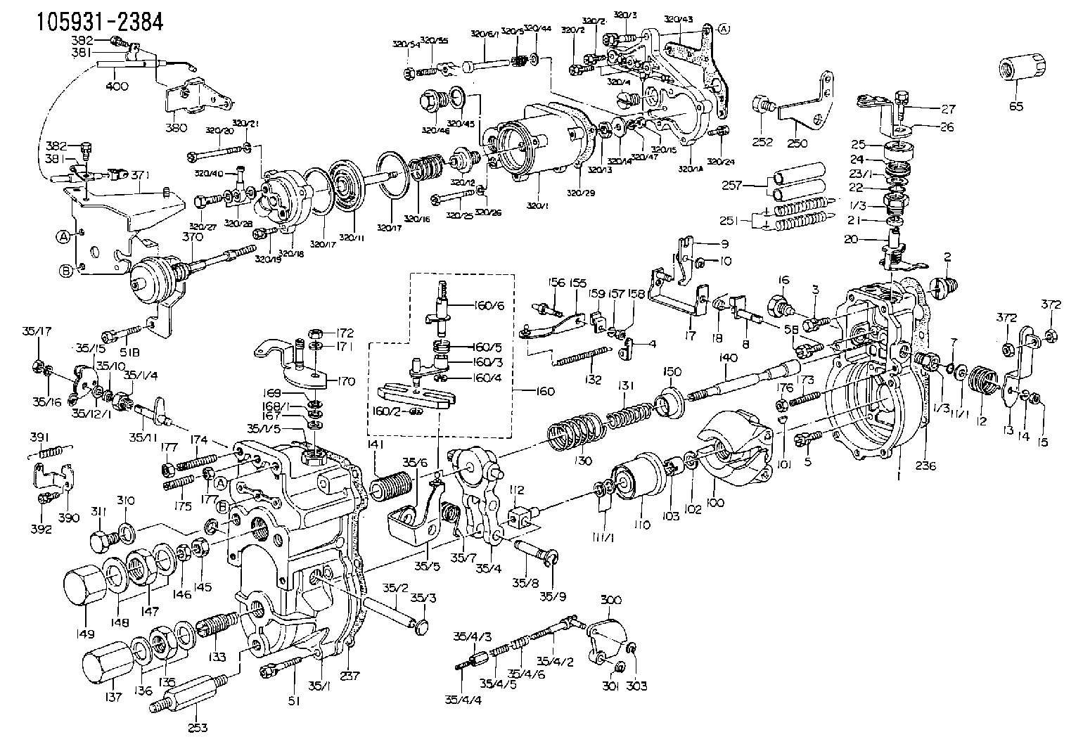
| 1. | [1] | 159200-2621 | GOVERNOR HOUSING |
| 1/3. | [2] | 154321-0400 | BUSHING |
| 1/3. | [2] | 154321-0400 | BUSHING |
| 2. | [1] | 154007-0200 | ADAPTOR |
| 3. | [1] | 020018-1840 | BLEEDER SCREW M8P1.25L18 |
| 4. | [1] | 159232-0201 | PLATE |
| 5. | [5] | 029010-6810 | BLEEDER SCREW |
| 5B. | [1] | 020106-1640 | BLEEDER SCREW M6P1.0L14 |
| 7. | [1] | 029631-0030 | O-RING &9.8W2.3 |
| 8. | [1] | 159205-2321 | LEVER SHAFT |
| 9. | [1] | 159202-0400 | CONTROL LEVER |
| 10. | [1] | 016010-0810 | LOCKING WASHER |
| 11/1. | [0] | 029311-0520 | SHIM D20.8&10.3T0.2 |
| 11/1. | [0] | 029311-0530 | SHIM D20.8&10.3T0.25 |
| 11/1. | [0] | 029311-0540 | SHIM D20.8&10.3T0.3 |
| 11/1. | [0] | 029311-0550 | SHIM D20.8&10.3T0.35 |
| 11/1. | [0] | 029311-0560 | SHIM D20.8&10.3T0.4 |
| 11/1. | [0] | 029311-0570 | SHIM D20.8&10.3T0.5 |
| 12. | [1] | 159215-0000 | COILED SPRING |
| 13. | [1] | 159242-6720 | CONTROL LEVER |
| 14. | [1] | 014110-8440 | LOCKING WASHER |
| 15. | [1] | 013020-8040 | UNION NUT M8P1.25H7 |
| 16. | [1] | 159237-0000 | CAPSULE |
| 17. | [1] | 159202-0920 | CONTROL LEVER |
| 18. | [1] | 159215-0300 | COILED SPRING |
| 20. | [1] | 159242-0220 | CONTROL LEVER |
| 21. | [1] | 159242-0600 | BUSHING |
| 22. | [1] | 029631-0030 | O-RING &9.8W2.3 |
| 23/1. | [0] | 029311-0520 | SHIM D20.8&10.3T0.2 |
| 23/1. | [0] | 029311-0530 | SHIM D20.8&10.3T0.25 |
| 23/1. | [0] | 029311-0540 | SHIM D20.8&10.3T0.3 |
| 23/1. | [0] | 029311-0550 | SHIM D20.8&10.3T0.35 |
| 23/1. | [0] | 029311-0560 | SHIM D20.8&10.3T0.4 |
| 23/1. | [0] | 029311-0570 | SHIM D20.8&10.3T0.5 |
| 24. | [1] | 159215-0000 | COILED SPRING |
| 25. | [1] | 154322-0100 | CAP |
| 26. | [1] | 159242-9520 | CONTROL LEVER |
| 27. | [1] | 020006-1640 | BLEEDER SCREW M6P1L16 4T |
| 35. | [1] | 159251-4622 | GOVERNOR COVER |
| 35/1. | [1] | 159201-3922 | GOVERNOR COVER |
| 35/2. | [1] | 159205-0400 | LEVER SHAFT |
| 35/3. | [2] | 159237-0200 | CAPSULE |
| 35/4. | [1] | 159253-0120 | TENSIONING LEVER |
| 35/4/1. | [1] | 159203-0120 | TENSIONING LEVER |
| 35/4/2. | [1] | 159204-5021 | RACK |
| 35/4/3. | [1] | 159233-0300 | UNION NUT |
| 35/4/4. | [1] | 159234-0000 | FLAT-HEAD SCREW |
| 35/4/5. | [1] | 159216-0000 | COILED SPRING |
| 35/4/6. | [1] | 159216-0100 | COILED SPRING |
| 35/5. | [1] | 159203-5020 | GUIDE LEVER |
| 35/6. | [2] | 159235-5000 | BUSHING |
| 35/7. | [1] | 159215-0201 | COILED SPRING |
| 35/8. | [1] | 159231-0800 | BEARING PIN |
| 35/9. | [2] | 016010-0610 | LOCKING WASHER |
| 35/10. | [1] | 029620-8050 | PACKING RING |
| 35/11. | [1] | 159225-6222 | LEVER SHAFT |
| 35/12/1. | [0] | 029310-8280 | SHIM D16.5&8T0.1 |
| 35/12/1. | [0] | 029310-8320 | SHIM D16.5&8T0.2 |
| 35/12/1. | [0] | 029310-8340 | SHIM D16.5&8T0.3 |
| 35/12/1. | [0] | 029310-8360 | SHIM D16.5&8T0.5 |
| 35/12/1. | [0] | 029310-8660 | SHIM D16.5&8T0.6 |
| 35/12/1. | [0] | 029310-8670 | SHIM D16.5&8T1.0 |
| 35/15. | [1] | 159225-6521 | CONTROL LEVER |
| 35/16. | [1] | 014110-8440 | LOCKING WASHER |
| 35/17. | [1] | 029200-8190 | UNION NUT |
| 51. | [5] | 020106-3840 | BLEEDER SCREW |
| 51B. | [2] | 020106-4540 | BLEEDER SCREW M6P1.0L45 |
| 65. | [1] | 155404-5700 | CAP |
| 100. | [1] | 154100-9520 | FLYWEIGHT ASSEMBLY |
| 101. | [1] | 025803-1610 | WOODRUFF KEY |
| 102. | [1] | 029321-2020 | LOCKING WASHER |
| 103. | [1] | 029231-2030 | UNION NUT |
| 110. | [1] | 154123-1020 | SLIDING PIECE |
| 111/1. | [0] | 029311-0010 | SHIM D14&10.1T0.2 |
| 111/1. | [0] | 029311-0180 | SHIM D14&10.1T0.3 |
| 111/1. | [0] | 029311-0190 | SHIM D14&10.1T0.40 |
| 111/1. | [0] | 029311-0210 | SHIM D14&10.1T1 |
| 111/1. | [0] | 139410-0000 | SHIM D14.0&10.1T0.5 |
| 111/1. | [0] | 139410-0100 | SHIM D14.0&10.1T1.5 |
| 111/1. | [0] | 139410-3000 | SHIM D14&10.1T2.0 |
| 111/1. | [0] | 139410-3100 | SHIM D14&10.1T3.0 |
| 111/1. | [0] | 139410-3200 | SHIM D14&10.1T4.0 |
| 112. | [1] | 159236-0100 | TERMINAL STUD |
| 130. | [1] | 159210-3500 | GOVERNOR SPRING |
| 131. | [1] | 159211-3000 | GOVERNOR SPRING |
| 132. | [1] | 159214-0000 | COILED SPRING |
| 133. | [1] | 159212-1820 | HEADLESS SCREW |
| 135. | [1] | 139220-0200 | UNION NUT |
| 136. | [2] | 026520-2440 | GASKET D23.9&20.2T1 |
| 137. | [1] | 159248-0700 | CAP |
| 140. | [1] | 159205-0301 | LEVER SHAFT |
| 141. | [1] | 159234-5200 | GUIDE SLEEVE |
| 145. | [1] | 159233-5000 | UNION NUT |
| 146. | [1] | 023020-8040 | UNION NUT M8P1H5 |
| 147. | [1] | 139222-0200 | UNION NUT |
| 148. | [2] | 026522-2740 | GASKET D26.9&22.2T1 |
| 149. | [1] | 159237-5000 | CAP |
| 150. | [1] | 159235-5300 | SLOTTED WASHER |
| 155. | [1] | 159204-0120 | STRAP |
| 156. | [1] | 159237-0300 | BLEEDER SCREW |
| 157. | [1] | 014110-5440 | LOCKING WASHER |
| 158. | [1] | 159233-5200 | UNION NUT |
| 159. | [1] | 159242-0800 | PLATE |
| 160. | [1] | 159252-0122 | LEVER GROUP |
| 160/1. | [1] | 159202-2200 | CONTROL LEVER |
| 160/2. | [1] | 016010-0810 | LOCKING WASHER |
| 160/3. | [1] | 159202-0220 | CONTROL LEVER |
| 160/4. | [1] | 016010-0810 | LOCKING WASHER |
| 160/5. | [1] | 159215-0400 | COILED SPRING |
| 160/6. | [1] | 159205-0621 | LEVER SHAFT |
| 167. | [1] | 029621-0080 | PACKING RING |
| 168/1. | [0] | 029311-0640 | SHIM D26.0&10.2T0.95 |
| 168/1. | [0] | 029311-0650 | SHIM D26.0&10.2T0.20 |
| 168/1. | [0] | 029311-0660 | SHIM D26.0&10.2T0.25 |
| 168/1. | [0] | 029311-0670 | SHIM D26.0&10.2T0.30 |
| 168/1. | [0] | 029311-0680 | SHIM D26.0&10.2T0.35 |
| 168/1. | [0] | 029311-0690 | SHIM D26.0&10.2T0.40 |
| 168/1. | [0] | 029311-0700 | SHIM D26.0&10.2T0.50 |
| 168/1. | [0] | 139410-1400 | SHIM D26&10.2T0.7 |
| 168/1. | [0] | 139410-1500 | SHIM D26&10.2T0.9 |
| 168/1. | [0] | 139410-1600 | SHIM D26&10.2T0.8 |
| 168/1. | [0] | 139410-2700 | SHIM D26&10.2T0.6 |
| 169. | [1] | 139410-2300 | SHIM |
| 170. | [1] | 159241-1020 | CONTROL LEVER |
| 171. | [1] | 014110-8440 | LOCKING WASHER |
| 172. | [1] | 013020-8040 | UNION NUT M8P1.25H7 |
| 173. | [1] | 155615-1100 | FLAT-HEAD SCREW M6P1.0L37 |
| 174. | [1] | 154010-0100 | FLAT-HEAD SCREW |
| 175. | [1] | 154010-0100 | FLAT-HEAD SCREW |
| 176. | [1] | 029240-6010 | UNION NUT M6P1.0H5* |
| 177. | [2] | 154011-0100 | HEXAGON NUT |
| 177. | [2] | 154011-0100 | HEXAGON NUT |
| 236. | [1] | 154390-0000 | GASKET |
| 237. | [1] | 159238-3100 | GASKET |
| 250. | [1] | 159225-1820 | BRACKET |
| 251. | [2] | 159243-1900 | COILED SPRING |
| 252. | [1] | 159248-0200 | BLEEDER SCREW |
| 253. | [1] | 159248-0401 | BLEEDER SCREW |
| 257. | [2] | 154156-0500 | TUBE |
| 300. | [1] | 159207-7500 | CAM PLATE |
| 301. | [1] | 016010-0840 | LOCKING WASHER |
| 303. | [1] | 016010-0540 | LOCKING WASHER |
| 310. | [1] | 026516-2040 | GASKET D19.9&16.2T1 |
| 311. | [1] | 159237-0100 | CAPSULE |
| 320. | [1] | 154417-6821 | MANIFOLD-PRESSURE COMP. |
| 320/1. | [1] | 154408-6821 | GOVERNOR HOUSING |
| 320/1A. | [1] | 154408-2700 | SPACER BUSHING |
| 320/2. | [3] | 020106-2540 | BLEEDER SCREW M6P1L25 |
| 320/2. | [3] | 020106-2540 | BLEEDER SCREW M6P1L25 |
| 320/3. | [1] | 020118-3040 | BLEEDER SCREW |
| 320/4. | [1] | 139916-0000 | CAPSULE |
| 320/5. | [1] | 159275-1400 | COILED SPRING |
| 320/6/1. | [1] | 159274-0120 | STOP PIN L125 |
| 320/6/1. | [1] | 159274-0220 | STOP PIN L127.50 |
| 320/6/1. | [1] | 159274-0320 | STOP PIN L128.00 |
| 320/6/1. | [1] | 159274-0420 | STOP PIN L127.00 |
| 320/6/1. | [1] | 159274-0520 | STOP PIN L126.00 |
| 320/6/1. | [1] | 159274-0620 | STOP PIN L129.00 |
| 320/6/1. | [1] | 159274-0720 | STOP PIN L128.50 |
| 320/6/1. | [1] | 159274-0820 | STOP PIN L125.50 |
| 320/6/1. | [1] | 159274-0920 | STOP PIN L126.50 |
| 320/6/1. | [1] | 159274-1120 | STOP PIN L119.5 |
| 320/6/1. | [1] | 159274-1220 | STOP PIN L120 |
| 320/6/1. | [1] | 159274-1320 | STOP PIN L120.5 |
| 320/6/1. | [1] | 159274-1420 | STOP PIN L121 |
| 320/6/1. | [1] | 159274-1520 | STOP PIN L121.5 |
| 320/6/1. | [1] | 159274-1620 | STOP PIN L122 |
| 320/6/1. | [1] | 159274-1720 | STOP PIN L122.5 |
| 320/6/1. | [1] | 159274-1820 | STOP PIN L123 |
| 320/6/1. | [1] | 159274-1920 | STOP PIN L123.5 |
| 320/6/1. | [1] | 159274-4220 | STOP PIN L129.5 |
| 320/6/1. | [1] | 159274-4320 | STOP PIN L130 |
| 320/6/1. | [1] | 159274-4420 | STOP PIN L130.5 |
| 320/6/1. | [1] | 159274-4520 | STOP PIN L131 |
| 320/6/1. | [1] | 159274-4620 | STOP PIN L131.5 |
| 320/6/1. | [1] | 159274-4720 | STOP PIN L132 |
| 320/6/1. | [1] | 159274-4820 | STOP PIN L132.5 |
| 320/6/1. | [1] | 159274-4920 | STOP PIN L133 |
| 320/6/1. | [1] | 159274-5020 | STOP PIN L133.5 |
| 320/11. | [1] | 154400-0820 | DIAPHRAGM |
| 320/12. | [1] | 154406-5300 | GUIDE SLEEVE |
| 320/13. | [1] | 154406-5400 | UNION NUT |
| 320/14. | [1] | 154406-5500 | SLOTTED WASHER |
| 320/15. | [1] | 013030-6010 | UNION NUT |
| 320/16. | [1] | 154403-8300 | COILED SPRING |
| 320/17. | [2] | 154413-2600 | GASKET |
| 320/17. | [2] | 154413-2600 | GASKET |
| 320/18. | [1] | 154404-4920 | COVER |
| 320/19. | [2] | 020106-2040 | BLEEDER SCREW M6P1L20 |
| 320/20. | [1] | 139006-7000 | BLEEDER SCREW |
| 320/21. | [1] | 014110-6440 | LOCKING WASHER |
| 320/24. | [3] | 020106-2040 | BLEEDER SCREW M6P1L20 |
| 320/25. | [1] | 139006-1300 | BLEEDER SCREW M6P1L76 |
| 320/26. | [1] | 014110-6440 | LOCKING WASHER |
| 320/27. | [1] | 029731-0180 | EYE BOLT |
| 320/28. | [2] | 026510-1340 | GASKET D13.4&10.2T1 |
| 320/29. | [1] | 154413-2800 | GASKET |
| 320/40. | [1] | 154412-7920 | JOINT CONNECTION |
| 320/43. | [1] | 154390-2100 | GASKET |
| 320/44. | [1] | 014010-5140 | PLAIN WASHER D12&5.5T0.8 |
| 320/45. | [1] | 029331-8040 | GASKET |
| 320/46. | [1] | 154406-5800 | FLAT-HEAD SCREW |
| 320/47. | [1] | 014110-6440 | LOCKING WASHER |
| 320/54. | [1] | 013030-6040 | UNION NUT M6P1H3.6 |
| 320/55. | [1] | 154404-4800 | FLAT-HEAD SCREW |
| 370. | [1] | 159248-3120 | ACTUATOR |
| 371. | [1] | 159225-7020 | BRACKET |
| 372. | [2] | 013030-6040 | UNION NUT M6P1H3.6 |
| 372. | [2] | 013030-6040 | UNION NUT M6P1H3.6 |
| 380. | [1] | 159225-8500 | BRACKET |
| 381. | [2] | 159225-7201 | CLAMPING BAND |
| 381. | [2] | 159225-7201 | CLAMPING BAND |
| 382. | [2] | 020146-1240 | BLEEDER SCREW M6P1.0L12 |
| 382. | [2] | 020146-1240 | BLEEDER SCREW M6P1.0L12 |
| 390. | [1] | 159225-6720 | BRACKET |
| 391. | [1] | 159225-6800 | COILED SPRING |
| 392. | [1] | 020106-1240 | BLEEDER SCREW M6P1.0L12 |
| 400. | [1] | 159225-7301 | WIRE |
Include in #1:
101401-0503
as GOVERNOR
Cross reference number
Zexel num
Bosch num
Firm num
Name
105931-2384
8941719192 ISUZU
GOVERNOR
K 14JK MECHANICAL GOVERNOR GOV RLD GOV
K 14JK MECHANICAL GOVERNOR GOV RLD GOV
Information:
start by: a) remove flywheel housingb) remove timing gear coverc) remove pistons 1. Turn the crankshaft until the "C" mark on crankshaft gear (2) is in alignment with the "C" mark on camshaft gear (1). 2. Put a mark across the teeth of the fuel pump drive gear and idler gear at location (X). Put a mark across the teeth of the idler gear and camshaft gear at location (Y). The marks are necessary for the correct timing of the camshaft for the fuel injection pump when the crankshaft is installed.3. Fasten a hoist to the crankshaft.4. Remove the caps for the crankshaft main bearings.5. Remove the crankshaft. Weight of the crankshaft is 200 lb. (91 kg).6. Remove the main bearings from the main bearing caps. Remove the crankshaft main bearings from the cylinder block. 7. Use tool (A) to remove the crankshaft gear and the oil seal wear sleeve.Install Crankshaft
1. Clean the bearing surfaces in the cylinder block. Install the upper halves of the main bearings in the block. Put clean SAE 30 engine oil on the bearings.2. Heat the crankshaft gear to a maximum temperature of 601°F (316°C). Install the gear on the crankshaft. Fasten a hoist to the crankshaft and put the crankshaft in position in the cylinder block with all timing marks in alignment.3. Clean the bearing surfaces of the main bearing caps. Install the lower halves of the main bearings in the caps. 4. Install Plastigage (A) on the bearing to check the bearing clearance. See INSTALL CRANKSHAFT MAIN BEARINGS for the correct bearing clearance procedure. The main bearing caps must be installed with the part number toward the front of the block. Make sure the number on the cap is the same number as the number on the left side of each cap saddle. 5. Install thrust plate (1) (bearing) in the No. 7 main bearing. The thrust bearing has a tab that fits into a machined area in the cylinder block. The tab will not let the thrust bearing be installed backward.6. Put clean SAE 30 engine oil on the cap bolt threads, face of the washers and lower halves of the main bearings. Put the caps in position on the engine. Install the bolts and washers. Tighten the bolts to a torque of 30 3 lb.ft. (40 4 N m). Put a mark across the bolt heads and bearing, and tighten the bolts 90° clockwise from the mark. 7. Check the crankshaft end play with tool group (B). End play with new bearings must be .0025 to .0145 in. (0.064 to 0.368 mm). Maximum permissible end play with used bearings is .025 in. (0.64 mm). The crankshaft end play is controlled by the thrust plates (bearings).8. If the fuel pump drive gear, idler gear, or camshaft gear has been removed or if a replacement of the crankshaft gear has been made, it will be necessary to put the engine into time after assembly. See INSTALL FUEL INJECTION PUMP
1. Clean the bearing surfaces in the cylinder block. Install the upper halves of the main bearings in the block. Put clean SAE 30 engine oil on the bearings.2. Heat the crankshaft gear to a maximum temperature of 601°F (316°C). Install the gear on the crankshaft. Fasten a hoist to the crankshaft and put the crankshaft in position in the cylinder block with all timing marks in alignment.3. Clean the bearing surfaces of the main bearing caps. Install the lower halves of the main bearings in the caps. 4. Install Plastigage (A) on the bearing to check the bearing clearance. See INSTALL CRANKSHAFT MAIN BEARINGS for the correct bearing clearance procedure. The main bearing caps must be installed with the part number toward the front of the block. Make sure the number on the cap is the same number as the number on the left side of each cap saddle. 5. Install thrust plate (1) (bearing) in the No. 7 main bearing. The thrust bearing has a tab that fits into a machined area in the cylinder block. The tab will not let the thrust bearing be installed backward.6. Put clean SAE 30 engine oil on the cap bolt threads, face of the washers and lower halves of the main bearings. Put the caps in position on the engine. Install the bolts and washers. Tighten the bolts to a torque of 30 3 lb.ft. (40 4 N m). Put a mark across the bolt heads and bearing, and tighten the bolts 90° clockwise from the mark. 7. Check the crankshaft end play with tool group (B). End play with new bearings must be .0025 to .0145 in. (0.064 to 0.368 mm). Maximum permissible end play with used bearings is .025 in. (0.64 mm). The crankshaft end play is controlled by the thrust plates (bearings).8. If the fuel pump drive gear, idler gear, or camshaft gear has been removed or if a replacement of the crankshaft gear has been made, it will be necessary to put the engine into time after assembly. See INSTALL FUEL INJECTION PUMP