Information governor
BOSCH
9 420 613 853
9420613853
ZEXEL
105923-4280
1059234280
MITSUBISHI
ME748155
me748155
Rating:
Scheme ###:
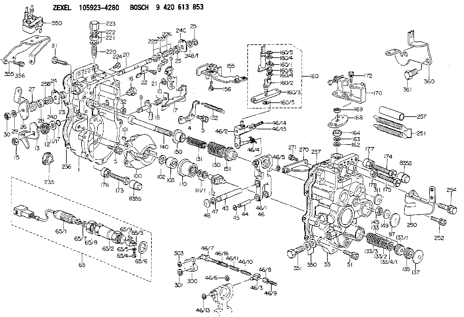
| 1. | [1] | 159360-0520 | GOVERNOR HOUSING |
| 4. | [1] | 159362-5520 | PLATE |
| 5. | [10] | 139006-6100 | BLEEDER SCREW |
| 5. | [10] | 139006-6100 | BLEEDER SCREW |
| 7. | [1] | 139709-0100 | O-RING |
| 8. | [1] | 159364-0120 | LEVER SHAFT |
| 9. | [1] | 159362-5620 | CONTROL LEVER |
| 10. | [1] | 016010-0740 | LOCKING WASHER |
| 11/1. | [0] | 029311-0220 | SHIM D18&10.3T0.2 |
| 11/1. | [0] | 029311-0230 | SHIM D18&10.3T0.5 |
| 11/1. | [0] | 029311-0430 | SHIM D18&10.3T0.30 |
| 11/1. | [0] | 029311-0440 | SHIM D18&10.3T0.40 |
| 11/1. | [0] | 029311-0450 | SHIM D18&10.3T0.25 |
| 11/1. | [0] | 029311-0460 | SHIM D18&10.3T0.35 |
| 11/1. | [0] | 139410-3300 | SHIM D18&10.3T0.6 |
| 11/1. | [0] | 139410-3400 | SHIM D18&10.3T0.8 |
| 11/1. | [0] | 139410-3500 | SHIM D18&10.3T0.9 |
| 12. | [1] | 159368-7800 | COILED SPRING |
| 13. | [1] | 159362-1500 | CONTROL LEVER |
| 15. | [1] | 013020-8040 | UNION NUT M8P1.25H7 |
| 16. | [1] | 159364-5000 | CAPSULE |
| 17. | [1] | 159362-0520 | CONTROL LEVER |
| 18. | [1] | 159215-0600 | COILED SPRING |
| 20. | [1] | 159364-3800 | LEVER SHAFT |
| 21. | [2] | 020104-1240 | BLEEDER SCREW |
| 22. | [1] | 159362-0600 | CONTROL LEVER |
| 23. | [2] | 139608-0600 | PACKING RING |
| 23. | [2] | 139608-0600 | PACKING RING |
| 24. | [1] | 159362-0700 | PLAIN WASHER |
| 24B/1. | [0] | 139408-1000 | SHIM D16&8T0.5 |
| 24B/1. | [0] | 139408-1300 | SHIM D16&8T0.2 |
| 24C. | [1] | 159362-0700 | PLAIN WASHER |
| 24D. | [1] | 139308-2100 | PLAIN WASHER |
| 25. | [1] | 159238-4200 | LOCKING WASHER |
| 25B. | [1] | 159238-4200 | LOCKING WASHER |
| 26. | [1] | 159390-2100 | CONTROL LEVER |
| 27. | [1] | 159368-7300 | COILED SPRING |
| 28. | [1] | 159364-6000 | BUSHING |
| 29. | [1] | 014110-8440 | LOCKING WASHER |
| 30. | [1] | 013020-8040 | UNION NUT M8P1.25H7 |
| 31. | [1] | 155644-1301 | BLEEDER SCREW |
| 32. | [1] | 013030-6040 | UNION NUT M6P1H3.6 |
| 35. | [1] | 159361-0520 | GOVERNOR COVER |
| 43. | [1] | 159364-0700 | LEVER SHAFT |
| 44. | [1] | 159364-0800 | BEARING PIN |
| 45. | [2] | 016010-0640 | LOCKING WASHER |
| 46. | [1] | 159363-5720 | TENSIONING LEVER |
| 46/1. | [1] | 159363-5620 | TENSIONING LEVER |
| 46/2. | [1] | 159362-8221 | GUIDE LEVER |
| 46/3. | [1] | 159364-4201 | BEARING PIN |
| 46/4. | [1] | 159368-6201 | COILED SPRING |
| 46/5. | [1] | 016010-0540 | LOCKING WASHER |
| 46/6. | [1] | 016010-0440 | LOCKING WASHER |
| 46/7. | [1] | 159364-4121 | RACK |
| 46/8. | [1] | 159364-4300 | UNION NUT |
| 46/9. | [1] | 159364-4400 | FLAT-HEAD SCREW |
| 46/10. | [1] | 159368-6900 | COILED SPRING |
| 46/11. | [1] | 159368-7000 | COILED SPRING |
| 46/13. | [1] | 016010-0540 | LOCKING WASHER |
| 46/14. | [1] | 159364-1900 | FLAT-HEAD SCREW |
| 46/15. | [1] | 159364-1800 | UNION NUT |
| 46/16. | [1] | 159368-9500 | COILED SPRING |
| 47. | [2] | 016110-1020 | LOCKING WASHER |
| 48. | [2] | 159237-0200 | CAPSULE |
| 51. | [9] | 020106-3840 | BLEEDER SCREW |
| 65. | [1] | 154611-9320 | RACK SENSOR ASSY |
| 65/1. | [1] | 479775-5320 | RACK SENSOR |
| 65/2. | [1] | 154614-4800 | JOINT CONNECTION |
| 65/3. | [1] | 154614-3100 | BLOCK |
| 65/4. | [1] | 010234-1040 | HEX-SOCKET-HEAD CAP SCREW |
| 65/5. | [1] | 014110-4440 | LOCKING WASHER |
| 65/6. | [1] | 026524-3040 | GASKET |
| 65/7A. | [0] | 029310-6220 | SHIM D11.5&6.5T0.10 |
| 65/7B. | [0] | 029310-6230 | SHIM D11.5&6.5T0.20 |
| 65/7C. | [0] | 029310-6240 | SHIM D11.5&6.5T0.25 |
| 65/7D. | [0] | 029310-6260 | SHIM D11.5&6.4T1.00 |
| 65/7E. | [0] | 029310-6270 | SHIM D11.5&6.4T1.20 |
| 65/7F. | [0] | 029310-6280 | SHIM D11.5&6.4T1.50 |
| 65/8. | [1] | 154614-1900 | UNION NUT |
| 65/9. | [1] | 154614-3300 | BEARING PIN |
| 97. | [1] | 159364-2000 | CAPSULE |
| 100. | [1] | 154100-9220 | FLYWEIGHT ASSEMBLY |
| 101. | [1] | 025803-1310 | WOODRUFF KEY |
| 102. | [1] | 029321-2020 | LOCKING WASHER |
| 103. | [1] | 029231-2030 | UNION NUT |
| 110. | [1] | 154123-2320 | SLIDING PIECE |
| 111/1. | [0] | 029311-0010 | SHIM D14&10.1T0.2 |
| 111/1. | [0] | 029311-0180 | SHIM D14&10.1T0.3 |
| 111/1. | [0] | 029311-0190 | SHIM D14&10.1T0.40 |
| 111/1. | [0] | 029311-0210 | SHIM D14&10.1T1 |
| 111/1. | [0] | 139410-0000 | SHIM D14.0&10.1T0.5 |
| 111/1. | [0] | 139410-0100 | SHIM D14.0&10.1T1.5 |
| 111/1. | [0] | 139410-3000 | SHIM D14&10.1T2.0 |
| 111/1. | [0] | 139410-3100 | SHIM D14&10.1T3.0 |
| 111/1. | [0] | 139410-3200 | SHIM D14&10.1T4.0 |
| 112. | [1] | 159364-5200 | TERMINAL STUD |
| 130. | [1] | 159367-1900 | GOVERNOR SPRING |
| 131. | [1] | 159367-6300 | GOVERNOR SPRING |
| 132. | [1] | 159368-6500 | COILED SPRING |
| 133. | [1] | 159368-2420 | SPRING PACK |
| 133/1. | [1] | 159364-2200 | GUIDE SLEEVE |
| 133/2. | [1] | 159368-0100 | COILED SPRING |
| 133/3. | [1] | 159368-0600 | COILED SPRING |
| 133/4/1. | [0] | 029311-0010 | SHIM D14&10.1T0.2 |
| 133/4/1. | [0] | 029311-0180 | SHIM D14&10.1T0.3 |
| 133/4/1. | [0] | 029311-0190 | SHIM D14&10.1T0.40 |
| 133/4/1. | [0] | 029311-0210 | SHIM D14&10.1T1 |
| 133/4/1. | [0] | 139410-0000 | SHIM D14.0&10.1T0.5 |
| 133/4/1. | [0] | 139410-0100 | SHIM D14.0&10.1T1.5 |
| 133/4/1. | [0] | 139410-3000 | SHIM D14&10.1T2.0 |
| 133/4/1. | [0] | 139410-3100 | SHIM D14&10.1T3.0 |
| 133/4/1. | [0] | 139410-3200 | SHIM D14&10.1T4.0 |
| 135. | [1] | 159364-2300 | FLAT-HEAD SCREW |
| 137. | [1] | 159364-2000 | CAPSULE |
| 140. | [1] | 159364-2500 | LEVER SHAFT |
| 145. | [1] | 159233-5700 | UNION NUT |
| 149. | [1] | 159237-5400 | CAPSULE |
| 150. | [1] | 159364-2600 | SLOTTED WASHER |
| 151. | [1] | 159364-2700 | SLOTTED WASHER |
| 155. | [1] | 159363-2721 | STRAP |
| 156. | [1] | 010235-1020 | HEX-SOCKET-HEAD CAP SCREW |
| 160. | [1] | 159362-2020 | LEVER GROUP |
| 160/1. | [1] | 159364-3220 | LEVER SHAFT |
| 160/2. | [1] | 159362-1020 | CONTROL LEVER |
| 160/3. | [1] | 159362-2000 | CONTROL LEVER |
| 160/4. | [2] | 159362-1300 | SHIM |
| 160/4. | [2] | 159362-1300 | SHIM |
| 160/5. | [2] | 016010-0840 | LOCKING WASHER |
| 160/5. | [2] | 016010-0840 | LOCKING WASHER |
| 160/6. | [1] | 159368-6600 | COILED SPRING |
| 162. | [1] | 139411-0600 | SHIM |
| 163. | [1] | 159238-3000 | LOCKING WASHER |
| 164. | [1] | 139610-0800 | PACKING RING |
| 168. | [1] | 159380-0300 | CONTROL LEVER |
| 169. | [1] | 013020-8040 | UNION NUT M8P1.25H7 |
| 170. | [1] | 159381-4820 | CONTROL LEVER |
| 172. | [3] | 020106-1240 | BLEEDER SCREW M6P1.0L12 |
| 173. | [1] | 154013-1700 | BLEEDER SCREW |
| 173B. | [1] | 154013-1800 | BLEEDER SCREW |
| 173C. | [1] | 154013-1900 | BLEEDER SCREW |
| 174. | [1] | 154013-2000 | BLEEDER SCREW |
| 175. | [1] | 154013-3300 | BLEEDER SCREW |
| 176. | [1] | 154011-4000 | UNION NUT |
| 177. | [1] | 154011-4100 | UNION NUT |
| 178. | [1] | 139210-0400 | UNION NUT |
| 220. | [1] | 159368-8420 | HEADLESS SCREW |
| 221. | [1] | 154011-4300 | UNION NUT |
| 222. | [2] | 026512-1540 | GASKET D15.4&12.2T1.50 |
| 223. | [1] | 154159-2100 | CAP NUT |
| 224. | [1] | 139006-0800 | BLEEDER SCREW |
| 225. | [2] | 029310-8050 | SHIM D13.5&8T0.5 |
| 226. | [1] | 159368-9101 | COILED SPRING |
| 227. | [1] | 159362-6720 | CONTROL LEVER |
| 235. | [1] | 155412-5200 | IMPELLER WHEEL |
| 236. | [1] | 154390-4200 | GASKET |
| 237. | [1] | 154390-2500 | GASKET |
| 250. | [1] | 159395-7520 | BRACKET |
| 251. | [2] | 154338-9300 | COILED SPRING |
| 252. | [2] | 020106-1240 | BLEEDER SCREW M6P1.0L12 |
| 254. | [1] | 020010-2040 | BLEEDER SCREW M10P1.25L20 |
| 257. | [2] | 154156-3100 | TUBE |
| 270. | [1] | 159362-7020 | GUIDE PLATE |
| 271. | [2] | 020106-1640 | BLEEDER SCREW M6P1.0L14 |
| 300. | [1] | 159372-1800 | CAM PLATE |
| 301. | [1] | 016010-0840 | LOCKING WASHER |
| 303. | [1] | 016010-0540 | LOCKING WASHER |
| 311. | [2] | 159237-5400 | CAPSULE |
| 350. | [2] | 139512-0000 | GASKET D17.2&12.2T1.0 |
| 351. | [1] | 139812-0100 | EYE BOLT |
| 355. | [1] | 159395-7600 | BRACKET |
| 356. | [3] | 020106-1240 | BLEEDER SCREW M6P1.0L12 |
| 360. | [1] | 159397-5601 | BRACKET |
| 361. | [2] | 010010-1840 | BLEEDER SCREW M10P1.5L18 |
| 550. | [1] | 153146-6020 | MICROSWITCH |
Include in #1:
108822-2920
as GOVERNOR
Cross reference number
Zexel num
Bosch num
Firm num
Name
Information:
Use the following tests for troubleshooting and repair steps. Use the ""Test for Cylinder Cutout"" in order to determine if the replacement of individual injectors is needed. Replace suspect injectors with the part number of the original injector. Use the ""Test for Leakage from Poppet Valve"" in order to determine if the full set of injectors need to be replaced. For replacement of the full set of injectors, use the current injectors and new software that is listed in Table 2.Test for Cylinder Cutout
The cylinder cutout test should be used in order to determine if an individual injector may have caused the failure.
Warm the engine out of cold mode.
Connect Cat ET to the engine while the engine is running.
Ensure that the engine speed is 1200 rpm 125 rpm. An extremely rough running engine will need to be diagnosed by other methods.
Cut out one bank of cylinders. Note engine rpm and the fuel position on the Cat ET screen at that time.
Cut out one of the remaining cylinders from the cylinder bank that is running. Allow the engine to stabilize, and note the fuel position.
Give power back to that cylinder. Allow the engine to stabilize. Note the fuel position.
Repeat steps 5 through 6 until the cylinder bank has been completely checked.
Power all cylinders. Allow the engine to stabilize.
Cut out the other cylinder bank and repeat steps 5 through 8.
Repeat steps 4 through 9 with the engine at 2000 rpm.
Compare the results from the fuel position from each cylinder.
If the cylinder was cut out and the fuel position did not change the cylinder may not have been producing power. This cylinder would be suspect.
When you are finished with the test, reduce engine RPM to low idle. Shut off the engine.
Replace any suspect injector with a similar original injector. Install new seals for the injector and the jumper tube during this repair. The repair procedure for the injector is found in Special Instruction, REHS0116.It is possible that multiple injectors are functioning improperly. Complete ""Test for Leakage from Poppet Valve"" in order to evaluate possible excessive leakage from the injectors.Test for Leakage from Poppet Valve
Warm the engine out of Cold Mode to normal operating temperature.
Turn off the engine.
Remove the valve cover bolts in preparation in order to observe the injectors. Leave the covers in place.
Hot oil and components can cause personal injury.Do not allow hot oil or components to contact skin.
Restart the engine and run at low idle with no load.
Use Cat ET in order to perform the test that overrides the injection actuation system. Increase injection actuation pressure to the maximum value.
Observe all of the injectors under each valve cover for leakage at the spill port. A small amount of dripping is acceptable. However, a continuous stream of oil is an indication of excessive leakage of the poppet valve. Only leaks at the spill port are an indication of excessive leakage from the poppet valve.
If multiple injectors display excessive leakage from the poppet valves, update the set of injectors with