Information governor
BOSCH
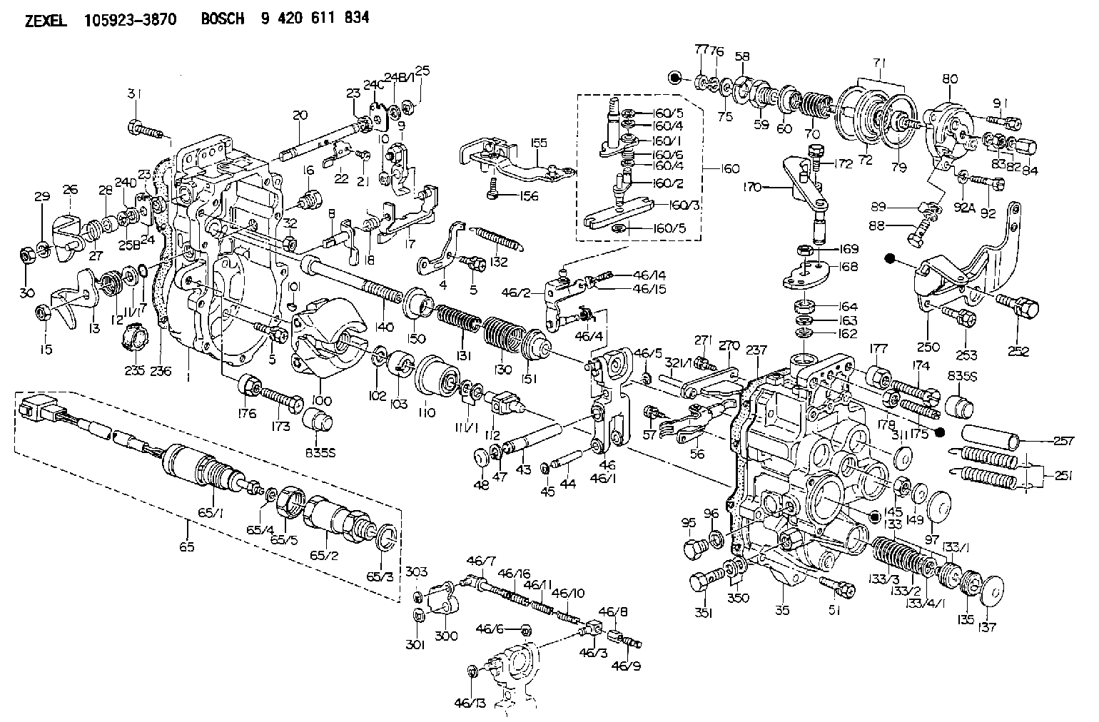
9 420 611 834
9420611834
ZEXEL
105923-3870
1059233870
ISUZU
1157709960
1157709960
Rating:
Scheme ###:
| 1. | [1] | 159360-0020 | GOVERNOR HOUSING |
| 4. | [1] | 159362-5520 | PLATE |
| 5. | [10] | 139006-6100 | BLEEDER SCREW |
| 5. | [10] | 139006-6100 | BLEEDER SCREW |
| 7. | [1] | 139709-0100 | O-RING |
| 8. | [1] | 159364-0120 | LEVER SHAFT |
| 9. | [1] | 159362-5620 | CONTROL LEVER |
| 10. | [1] | 016010-0740 | LOCKING WASHER |
| 11/1. | [0] | 029311-0220 | SHIM D18&10.3T0.2 |
| 11/1. | [0] | 029311-0230 | SHIM D18&10.3T0.5 |
| 11/1. | [0] | 029311-0430 | SHIM D18&10.3T0.30 |
| 11/1. | [0] | 029311-0440 | SHIM D18&10.3T0.40 |
| 11/1. | [0] | 029311-0450 | SHIM D18&10.3T0.25 |
| 11/1. | [0] | 029311-0460 | SHIM D18&10.3T0.35 |
| 11/1. | [0] | 139410-3300 | SHIM D18&10.3T0.6 |
| 11/1. | [0] | 139410-3400 | SHIM D18&10.3T0.8 |
| 11/1. | [0] | 139410-3500 | SHIM D18&10.3T0.9 |
| 12. | [1] | 159368-7800 | COILED SPRING |
| 13. | [1] | 159362-1500 | CONTROL LEVER |
| 15. | [1] | 013020-8040 | UNION NUT M8P1.25H7 |
| 16. | [1] | 159364-5000 | CAPSULE |
| 17. | [1] | 159362-0520 | CONTROL LEVER |
| 18. | [1] | 159215-0600 | COILED SPRING |
| 20. | [1] | 159364-3800 | LEVER SHAFT |
| 21. | [2] | 020104-1240 | BLEEDER SCREW |
| 22. | [1] | 159362-0600 | CONTROL LEVER |
| 23. | [2] | 139608-0600 | PACKING RING |
| 23. | [2] | 139608-0600 | PACKING RING |
| 24. | [1] | 159362-0700 | PLAIN WASHER |
| 24B/1. | [0] | 139408-1000 | SHIM D16&8T0.5 |
| 24B/1. | [0] | 139408-1300 | SHIM D16&8T0.2 |
| 24C. | [1] | 159362-0700 | PLAIN WASHER |
| 24D. | [1] | 139308-2100 | PLAIN WASHER |
| 25. | [1] | 159238-4200 | LOCKING WASHER |
| 25B. | [1] | 159238-4200 | LOCKING WASHER |
| 26. | [1] | 159390-9720 | CONTROL LEVER |
| 27. | [1] | 159368-7300 | COILED SPRING |
| 28. | [1] | 159364-6000 | BUSHING |
| 29. | [1] | 014110-8440 | LOCKING WASHER |
| 30. | [1] | 013020-8040 | UNION NUT M8P1.25H7 |
| 31. | [1] | 155644-1301 | BLEEDER SCREW |
| 32. | [1] | 013030-6040 | UNION NUT M6P1H3.6 |
| 35. | [1] | 159361-1720 | GOVERNOR COVER |
| 43. | [1] | 159364-0700 | LEVER SHAFT |
| 44. | [1] | 159364-0800 | BEARING PIN |
| 45. | [2] | 016010-0640 | LOCKING WASHER |
| 46. | [1] | 159363-5720 | TENSIONING LEVER |
| 46/1. | [1] | 159363-5620 | TENSIONING LEVER |
| 46/2. | [1] | 159362-8221 | GUIDE LEVER |
| 46/3. | [1] | 159364-4201 | BEARING PIN |
| 46/4. | [1] | 159368-6201 | COILED SPRING |
| 46/5. | [1] | 016010-0540 | LOCKING WASHER |
| 46/6. | [1] | 016010-0440 | LOCKING WASHER |
| 46/7. | [1] | 159364-4121 | RACK |
| 46/8. | [1] | 159364-4300 | UNION NUT |
| 46/9. | [1] | 159364-4400 | FLAT-HEAD SCREW |
| 46/10. | [1] | 159368-6900 | COILED SPRING |
| 46/11. | [1] | 159368-7000 | COILED SPRING |
| 46/13. | [1] | 016010-0540 | LOCKING WASHER |
| 46/14. | [1] | 159364-1900 | FLAT-HEAD SCREW |
| 46/15. | [1] | 159364-1800 | UNION NUT |
| 46/16. | [1] | 159368-9500 | COILED SPRING |
| 47. | [2] | 016110-1020 | LOCKING WASHER |
| 48. | [2] | 159237-0200 | CAPSULE |
| 51. | [9] | 020106-3840 | BLEEDER SCREW |
| 56. | [1] | 159362-3220 | LEVER GROUP |
| 57. | [2] | 020105-1040 | BLEEDER SCREW M5P0.8L10 |
| 58. | [1] | 146711-0000 | PLATE |
| 59. | [1] | 154415-1200 | BUSHING |
| 60. | [1] | 154415-1300 | UNION NUT |
| 65. | [1] | 154612-0421 | RACK SENSOR ASSY |
| 65/1. | [1] | 407945-0171 | RACK SENSOR |
| 65/2. | [1] | 154614-2500 | JOINT CONNECTION |
| 65/3. | [1] | 026524-3040 | GASKET |
| 65/4. | [1] | 029310-6280 | SHIM D11.5&6.4T1.50 |
| 65/5. | [1] | 154614-1900 | UNION NUT |
| 70. | [1] | 154402-1600 | COILED SPRING |
| 71. | [2] | 154413-2600 | GASKET |
| 72. | [1] | 154415-1020 | DIAPHRAGM |
| 75. | [1] | 154415-1100 | SLOTTED WASHER |
| 76. | [1] | 014110-6440 | LOCKING WASHER |
| 77. | [1] | 013030-6010 | UNION NUT |
| 79. | [1] | 154404-4400 | FLAT-HEAD SCREW |
| 80. | [1] | 154404-5100 | COVER |
| 82. | [2] | 139506-0300 | GASKET |
| 83. | [1] | 013030-6040 | UNION NUT M6P1H3.6 |
| 84. | [1] | 154035-1600 | CAP NUT |
| 88. | [1] | 029731-0180 | EYE BOLT |
| 89. | [2] | 139510-0200 | GASKET |
| 91. | [1] | 020106-2040 | BLEEDER SCREW M6P1L20 |
| 92. | [2] | 139006-7000 | BLEEDER SCREW |
| 92A. | [2] | 014110-6440 | LOCKING WASHER |
| 95. | [1] | 029111-2090 | CAPSULE |
| 96. | [1] | 139512-0000 | GASKET D17.2&12.2T1.0 |
| 97. | [1] | 159364-2000 | CAPSULE |
| 100. | [1] | 154100-9220 | FLYWEIGHT ASSEMBLY |
| 101. | [1] | 025803-1310 | WOODRUFF KEY |
| 102. | [1] | 029321-2020 | LOCKING WASHER |
| 103. | [1] | 029231-2030 | UNION NUT |
| 110. | [1] | 154123-2320 | SLIDING PIECE |
| 111/1. | [0] | 029311-0010 | SHIM D14&10.1T0.2 |
| 111/1. | [0] | 029311-0180 | SHIM D14&10.1T0.3 |
| 111/1. | [0] | 029311-0190 | SHIM D14&10.1T0.40 |
| 111/1. | [0] | 029311-0210 | SHIM D14&10.1T1 |
| 111/1. | [0] | 139410-0000 | SHIM D14.0&10.1T0.5 |
| 111/1. | [0] | 139410-0100 | SHIM D14.0&10.1T1.5 |
| 111/1. | [0] | 139410-3000 | SHIM D14&10.1T2.0 |
| 111/1. | [0] | 139410-3100 | SHIM D14&10.1T3.0 |
| 111/1. | [0] | 139410-3200 | SHIM D14&10.1T4.0 |
| 112. | [1] | 159364-2100 | TERMINAL STUD |
| 130. | [1] | 159367-3300 | GOVERNOR SPRING |
| 131. | [1] | 159367-6700 | GOVERNOR SPRING |
| 132. | [1] | 159368-6500 | COILED SPRING |
| 133. | [1] | 159368-2620 | SPRING PACK |
| 133/1. | [1] | 159364-2200 | GUIDE SLEEVE |
| 133/2. | [1] | 159368-0100 | COILED SPRING |
| 133/3. | [1] | 159368-0700 | COILED SPRING |
| 133/4/1. | [0] | 029311-0010 | SHIM D14&10.1T0.2 |
| 133/4/1. | [0] | 029311-0180 | SHIM D14&10.1T0.3 |
| 133/4/1. | [0] | 029311-0190 | SHIM D14&10.1T0.40 |
| 133/4/1. | [0] | 029311-0210 | SHIM D14&10.1T1 |
| 133/4/1. | [0] | 139410-0000 | SHIM D14.0&10.1T0.5 |
| 133/4/1. | [0] | 139410-0100 | SHIM D14.0&10.1T1.5 |
| 133/4/1. | [0] | 139410-3000 | SHIM D14&10.1T2.0 |
| 133/4/1. | [0] | 139410-3100 | SHIM D14&10.1T3.0 |
| 133/4/1. | [0] | 139410-3200 | SHIM D14&10.1T4.0 |
| 135. | [1] | 159364-2300 | FLAT-HEAD SCREW |
| 137. | [1] | 159364-2000 | CAPSULE |
| 140. | [1] | 159364-2500 | LEVER SHAFT |
| 145. | [1] | 159233-5700 | UNION NUT |
| 149. | [1] | 159237-5400 | CAPSULE |
| 150. | [1] | 159364-2600 | SLOTTED WASHER |
| 151. | [1] | 159364-2700 | SLOTTED WASHER |
| 155. | [1] | 159363-2321 | STRAP |
| 156. | [1] | 010235-1020 | HEX-SOCKET-HEAD CAP SCREW |
| 160. | [1] | 159362-2020 | LEVER GROUP |
| 160/1. | [1] | 159364-3220 | LEVER SHAFT |
| 160/2. | [1] | 159362-1020 | CONTROL LEVER |
| 160/3. | [1] | 159362-2000 | CONTROL LEVER |
| 160/4. | [2] | 159362-1300 | SHIM |
| 160/4. | [2] | 159362-1300 | SHIM |
| 160/5. | [2] | 016010-0840 | LOCKING WASHER |
| 160/5. | [2] | 016010-0840 | LOCKING WASHER |
| 160/6. | [1] | 159368-6600 | COILED SPRING |
| 162. | [1] | 139411-0600 | SHIM |
| 163. | [1] | 159238-3000 | LOCKING WASHER |
| 164. | [1] | 139610-0800 | PACKING RING |
| 168. | [1] | 159380-0300 | CONTROL LEVER |
| 169. | [1] | 013020-8040 | UNION NUT M8P1.25H7 |
| 170. | [1] | 159382-8921 | CONTROL LEVER |
| 172. | [2] | 020106-1240 | BLEEDER SCREW M6P1.0L12 |
| 173. | [1] | 154013-1700 | BLEEDER SCREW |
| 173B. | [1] | 154013-1800 | BLEEDER SCREW |
| 173C. | [1] | 154013-1900 | BLEEDER SCREW |
| 174. | [1] | 154013-2000 | BLEEDER SCREW |
| 175. | [1] | 154013-2100 | FLAT-HEAD SCREW |
| 176. | [1] | 154011-4000 | UNION NUT |
| 177. | [1] | 154011-4100 | UNION NUT |
| 178. | [1] | 013131-0040 | UNION NUT M10P1.25H6 |
| 235. | [1] | 155412-5300 | IMPELLER WHEEL |
| 236. | [1] | 154390-4200 | GASKET |
| 237. | [1] | 154390-2500 | GASKET |
| 250. | [1] | 159399-5420 | BRACKET |
| 251. | [2] | 154339-6500 | COILED SPRING |
| 252. | [1] | 010110-1640 | BLEEDER SCREW M101.25L16 |
| 253. | [2] | 020106-1240 | BLEEDER SCREW M6P1.0L12 |
| 257. | [2] | 154156-0900 | TUBE |
| 270. | [1] | 159362-2120 | GUIDE PLATE |
| 271. | [2] | 020106-1640 | BLEEDER SCREW M6P1.0L14 |
| 300. | [1] | 159374-4000 | CAM PLATE |
| 301. | [1] | 016010-0840 | LOCKING WASHER |
| 303. | [1] | 016010-0540 | LOCKING WASHER |
| 311. | [2] | 159237-5400 | CAPSULE |
| 321/1. | [1] | 159274-5100 | STOP PIN L72.5 |
| 321/1. | [1] | 159274-5200 | STOP PIN L73 |
| 321/1. | [1] | 159274-5300 | STOP PIN L73.5 |
| 321/1. | [1] | 159274-5400 | STOP PIN L74 |
| 321/1. | [1] | 159274-5500 | STOP PIN L74.5 |
| 321/1. | [1] | 159274-5600 | STOP PIN L75 |
| 321/1. | [1] | 159274-5700 | STOP PIN L75.5 |
| 321/1. | [1] | 159274-5800 | STOP PIN L76 |
| 321/1. | [1] | 159274-5900 | STOP PIN L76.5 |
| 321/1. | [1] | 159274-6000 | STOP PIN L77 |
| 321/1. | [1] | 159274-6100 | STOP PIN L77.5 |
| 321/1. | [1] | 159274-6200 | STOP PIN L78 |
| 321/1. | [1] | 159274-6300 | STOP PIN L78.5 |
| 321/1. | [1] | 159274-6400 | STOP PIN L79 |
| 321/1. | [1] | 159274-6500 | STOP PIN L79.5 |
| 321/1. | [1] | 159274-6600 | STOP PIN L80 |
| 321/1. | [1] | 159274-6700 | STOP PIN L80.5 |
| 321/1. | [1] | 159274-6800 | STOP PIN L81 |
| 321/1. | [1] | 159274-6900 | STOP PIN L81.5 |
| 321/1. | [1] | 159274-7000 | STOP PIN L82 |
| 321/1. | [1] | 159274-7100 | STOP PIN L82.5 |
| 321/1. | [1] | 159274-7200 | STOP PIN L83 |
| 321/1. | [1] | 159274-7300 | STOP PIN L83.5 |
| 321/1. | [1] | 159274-7400 | STOP PIN L84 |
| 321/1. | [1] | 159274-7500 | STOP PIN L84.5 |
| 321/1. | [1] | 159274-7600 | STOP PIN L85 |
| 321/1. | [1] | 159274-7700 | STOP PIN L85.5 |
| 321/1. | [1] | 159274-7800 | STOP PIN L86 |
| 321/1. | [1] | 159274-7900 | STOP PIN L86.5 |
| 321/1. | [1] | 159274-8000 | STOP PIN L87 |
| 321/1. | [1] | 159274-8100 | STOP PIN L87.5 |
| 321/1. | [1] | 159274-8200 | STOP PIN L88 |
| 321/1. | [1] | 159274-8300 | STOP PIN L88.5 |
| 321/1. | [1] | 159274-8400 | STOP PIN L89 |
| 321/1. | [1] | 159274-8500 | STOP PIN L89.5 |
| 321/1. | [1] | 159274-8600 | STOP PIN L90 |
| 350. | [2] | 139512-0000 | GASKET D17.2&12.2T1.0 |
| 351. | [1] | 139812-0100 | EYE BOLT |
Include in #1:
108622-1080
as GOVERNOR
Cross reference number
Zexel num
Bosch num
Firm num
Name
Information:
Problem 2
The engine does not crank.
Check the engine mounted start switch (EMSS).
Ensure that the emergency stop switch (ES) has been reset.
Place a switch across the terminals of the EMSS.
Close the switch momentarily, but do not start the engine.
Remove the switch when the test is completed. Result
The engine cranks.The EMSS is faulty or the circuit breaker (CB2) must be reset.
The engine does not crank.Go to Step 3.
Check the start/stop switch.
Ensure that the emergency stop switch (ES) has been reset.
Connect a switch with a 2 amp capacity between terminals (TS-21) and (TS-26) of the junction box.
Close the switch momentarily, but do not start the engine.
Disconnect the switch after the test is completed. Results
The engine cranks.The start/stop switch is faulty or the wiring to the switch is faulty. Replace the switch or repair the wiring. The circuit breaker (CB2) may need to be reset.
The engine does not crank.Go to Step 3.
Check the emergency stop switch (ES).
Ensure that the emergency stop switch (ES) has been reset.
Connect a switch with a 2 amp capacity between terminals (TS-26) and (TS-24) of the junction box.
Close the switch momentarily but do not start the engine.
Disconnect the switch after the test is completed. Result
The engine cranks.The emergency stop switch (ES) is faulty.
The engine does not crank.Reset the circuit breaker (CB5) and repeat Step 3. If the engine does not crank go to Step 4.
Check the components of the starting system.
Check the voltage at terminal (TS-24) of the junction box. Result
The voltage is low. Low voltage is between 1 volt and 20 volts.Charge the battery or repair the loose connections between the battery cable terminal and the battery. STOP.
The voltage is above 20 volts.The magnetic switch (MS), the pinion solenoid (PS), or the starting motor (SM) is faulty. The circuit breaker (CB2) may need to be reset. Reset the circuit breaker and repair the component that is faulty.
The voltage is zero (less than 1 volt).The circuit breaker (CB5) is being overloaded or the circuit breaker is faulty. Repair the short circuit or replace the circuit breaker. STOP.Problem 3
The engine starts and shutdown occurs immediately, or engine cranking terminates.
Check the protection switches.
Measure the voltage at terminal (SR2-30) while you crank the engine. Result
The voltage is above 10 volts while you crank the engine. The voltage then decreases to zero when the engine shuts down.The emergency stop switch (ES), the water temperature contactor switch (WTS), and the start/stop switch are opening. Check the start/stop switch first. The switch may be open across the common pair of contacts for the START/RUN switch when the switch is in the START position. The switch may also be open when the switch is released from the START position. Go to Step 7 of "Problem 1".
The voltage is above 10 volts at all times.The diode (D2) is faulty or there is a short across the diode circuit. The engine oil pressure switch (OPS1) may also have an intermittent short in the switch or in the connection. Refer