Information governor
BOSCH
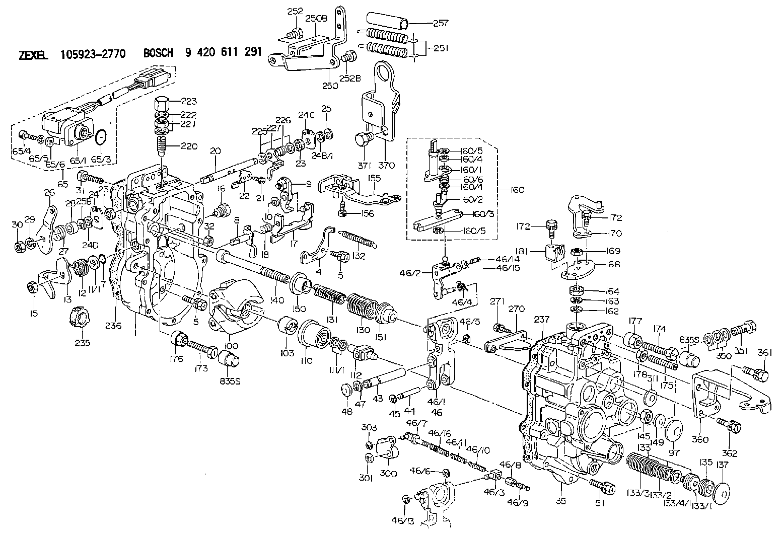
9 420 611 291
9420611291
ZEXEL
105923-2770
1059232770
ISUZU
1157709480
1157709480
Rating:
Scheme ###:
| 1. | [1] | 159360-0420 | GOVERNOR HOUSING |
| 4. | [1] | 159362-5520 | PLATE |
| 5. | [8] | 139006-6100 | BLEEDER SCREW |
| 5. | [8] | 139006-6100 | BLEEDER SCREW |
| 7. | [1] | 139709-0100 | O-RING |
| 8. | [1] | 159364-0120 | LEVER SHAFT |
| 9. | [1] | 159362-5720 | CONTROL LEVER |
| 10. | [1] | 016010-0740 | LOCKING WASHER |
| 11/1. | [0] | 029311-0220 | SHIM D18&10.3T0.2 |
| 11/1. | [0] | 029311-0230 | SHIM D18&10.3T0.5 |
| 11/1. | [0] | 029311-0430 | SHIM D18&10.3T0.30 |
| 11/1. | [0] | 029311-0440 | SHIM D18&10.3T0.40 |
| 11/1. | [0] | 029311-0450 | SHIM D18&10.3T0.25 |
| 11/1. | [0] | 029311-0460 | SHIM D18&10.3T0.35 |
| 11/1. | [0] | 139410-3300 | SHIM D18&10.3T0.6 |
| 11/1. | [0] | 139410-3400 | SHIM D18&10.3T0.8 |
| 11/1. | [0] | 139410-3500 | SHIM D18&10.3T0.9 |
| 12. | [1] | 159368-7800 | COILED SPRING |
| 13. | [1] | 159362-0400 | CONTROL LEVER |
| 15. | [1] | 013020-8040 | UNION NUT M8P1.25H7 |
| 16. | [1] | 159364-5000 | CAPSULE |
| 17. | [1] | 159362-2820 | CONTROL LEVER |
| 18. | [1] | 159215-0600 | COILED SPRING |
| 20. | [1] | 159364-3800 | LEVER SHAFT |
| 21. | [2] | 020104-1240 | BLEEDER SCREW |
| 22. | [1] | 159362-0600 | CONTROL LEVER |
| 23. | [2] | 139608-0600 | PACKING RING |
| 23. | [2] | 139608-0600 | PACKING RING |
| 24. | [1] | 159362-0700 | PLAIN WASHER |
| 24B/1. | [0] | 139408-1000 | SHIM D16&8T0.5 |
| 24B/1. | [0] | 139408-1300 | SHIM D16&8T0.2 |
| 24C. | [1] | 159362-0700 | PLAIN WASHER |
| 24D. | [1] | 139308-2100 | PLAIN WASHER |
| 25. | [1] | 159238-4200 | LOCKING WASHER |
| 25B. | [1] | 159238-4200 | LOCKING WASHER |
| 26. | [1] | 159390-1320 | CONTROL LEVER |
| 27. | [1] | 159368-7300 | COILED SPRING |
| 28. | [1] | 159364-6000 | BUSHING |
| 29. | [1] | 014110-8440 | LOCKING WASHER |
| 30. | [1] | 013020-8040 | UNION NUT M8P1.25H7 |
| 31. | [1] | 155644-1301 | BLEEDER SCREW |
| 32. | [1] | 013030-6040 | UNION NUT M6P1H3.6 |
| 35. | [1] | 159361-1820 | GOVERNOR COVER |
| 43. | [1] | 159364-0700 | LEVER SHAFT |
| 44. | [1] | 159364-0800 | BEARING PIN |
| 45. | [2] | 016010-0640 | LOCKING WASHER |
| 46. | [1] | 159363-5720 | TENSIONING LEVER |
| 46/1. | [1] | 159363-5620 | TENSIONING LEVER |
| 46/2. | [1] | 159362-8221 | GUIDE LEVER |
| 46/3. | [1] | 159364-4201 | BEARING PIN |
| 46/4. | [1] | 159368-6201 | COILED SPRING |
| 46/5. | [1] | 016010-0540 | LOCKING WASHER |
| 46/6. | [1] | 016010-0440 | LOCKING WASHER |
| 46/7. | [1] | 159364-4121 | RACK |
| 46/8. | [1] | 159364-4300 | UNION NUT |
| 46/9. | [1] | 159364-4400 | FLAT-HEAD SCREW |
| 46/10. | [1] | 159368-6900 | COILED SPRING |
| 46/11. | [1] | 159368-7000 | COILED SPRING |
| 46/13. | [1] | 016010-0540 | LOCKING WASHER |
| 46/14. | [1] | 159364-1900 | FLAT-HEAD SCREW |
| 46/15. | [1] | 159364-1800 | UNION NUT |
| 46/16. | [1] | 159368-9500 | COILED SPRING |
| 47. | [2] | 016110-1020 | LOCKING WASHER |
| 48. | [2] | 159237-0200 | CAPSULE |
| 51. | [9] | 020106-3840 | BLEEDER SCREW |
| 65. | [1] | 154611-0521 | RACK SENSOR ASSY |
| 65/1. | [1] | 407945-0012 | RACK SENSOR |
| 65/3. | [1] | 139726-0000 | O-RING |
| 65/4. | [2] | 010206-2040 | HEX-SOCKET-HEAD CAP SCREW |
| 65/5. | [2] | 029320-6010 | LOCKING WASHER |
| 65/6. | [2] | 014010-6140 | PLAIN WASHER D13&6.5T1 |
| 97. | [1] | 159364-2000 | CAPSULE |
| 100. | [1] | 154101-4120 | FLYWEIGHT ASSEMBLY |
| 103. | [1] | 154101-2500 | HEXAGON NUT |
| 110. | [1] | 154123-2320 | SLIDING PIECE |
| 111/1. | [0] | 029311-0010 | SHIM D14&10.1T0.2 |
| 111/1. | [0] | 029311-0180 | SHIM D14&10.1T0.3 |
| 111/1. | [0] | 029311-0190 | SHIM D14&10.1T0.40 |
| 111/1. | [0] | 029311-0210 | SHIM D14&10.1T1 |
| 111/1. | [0] | 139410-0000 | SHIM D14.0&10.1T0.5 |
| 111/1. | [0] | 139410-0100 | SHIM D14.0&10.1T1.5 |
| 111/1. | [0] | 139410-3000 | SHIM D14&10.1T2.0 |
| 111/1. | [0] | 139410-3100 | SHIM D14&10.1T3.0 |
| 111/1. | [0] | 139410-3200 | SHIM D14&10.1T4.0 |
| 112. | [1] | 159364-2400 | TERMINAL STUD |
| 130. | [1] | 159367-3500 | GOVERNOR SPRING |
| 131. | [1] | 159367-6200 | GOVERNOR SPRING |
| 132. | [1] | 159369-1900 | COILED SPRING |
| 133. | [1] | 159368-2120 | SPRING PACK |
| 133/1. | [1] | 159364-2200 | GUIDE SLEEVE |
| 133/2. | [1] | 159368-0100 | COILED SPRING |
| 133/3. | [1] | 159368-0400 | COILED SPRING |
| 133/4/1. | [0] | 029311-0010 | SHIM D14&10.1T0.2 |
| 133/4/1. | [0] | 029311-0180 | SHIM D14&10.1T0.3 |
| 133/4/1. | [0] | 029311-0190 | SHIM D14&10.1T0.40 |
| 133/4/1. | [0] | 029311-0210 | SHIM D14&10.1T1 |
| 133/4/1. | [0] | 139410-0000 | SHIM D14.0&10.1T0.5 |
| 133/4/1. | [0] | 139410-0100 | SHIM D14.0&10.1T1.5 |
| 133/4/1. | [0] | 139410-3000 | SHIM D14&10.1T2.0 |
| 133/4/1. | [0] | 139410-3000 | SHIM D14&10.1T2.0 |
| 133/4/1. | [0] | 139410-3100 | SHIM D14&10.1T3.0 |
| 133/4/1. | [0] | 139410-3200 | SHIM D14&10.1T4.0 |
| 135. | [1] | 159364-2300 | FLAT-HEAD SCREW |
| 137. | [1] | 159364-2000 | CAPSULE |
| 140. | [1] | 159364-2500 | LEVER SHAFT |
| 145. | [1] | 159233-5700 | UNION NUT |
| 149. | [1] | 159237-5400 | CAPSULE |
| 150. | [1] | 159364-2600 | SLOTTED WASHER |
| 151. | [1] | 159364-2700 | SLOTTED WASHER |
| 155. | [1] | 159363-2521 | STRAP |
| 156. | [1] | 010235-1020 | HEX-SOCKET-HEAD CAP SCREW |
| 160. | [1] | 159362-5820 | LEVER GROUP |
| 160/1. | [1] | 159364-6520 | LEVER SHAFT |
| 160/2. | [1] | 159362-5921 | CONTROL LEVER |
| 160/3. | [1] | 159362-2000 | CONTROL LEVER |
| 160/4. | [2] | 159362-1300 | SHIM |
| 160/4. | [2] | 159362-1300 | SHIM |
| 160/5. | [2] | 016010-0840 | LOCKING WASHER |
| 160/5. | [2] | 016010-0840 | LOCKING WASHER |
| 160/6. | [1] | 159368-8600 | COILED SPRING |
| 162. | [1] | 139411-0600 | SHIM |
| 163. | [1] | 159238-3000 | LOCKING WASHER |
| 164. | [1] | 139610-0800 | PACKING RING |
| 168. | [1] | 159380-0300 | CONTROL LEVER |
| 169. | [1] | 013020-8040 | UNION NUT M8P1.25H7 |
| 170. | [1] | 159380-6120 | CONTROL LEVER |
| 172. | [4] | 020106-1240 | BLEEDER SCREW M6P1.0L12 |
| 172. | [4] | 020106-1240 | BLEEDER SCREW M6P1.0L12 |
| 173. | [1] | 154013-1700 | BLEEDER SCREW |
| 173B. | [1] | 154013-1800 | BLEEDER SCREW |
| 173C. | [1] | 154013-1900 | BLEEDER SCREW |
| 174. | [1] | 154013-2000 | BLEEDER SCREW |
| 175. | [1] | 154013-2800 | FLAT-HEAD SCREW |
| 176. | [1] | 154011-4000 | UNION NUT |
| 177. | [1] | 154011-4100 | UNION NUT |
| 178. | [1] | 013131-0040 | UNION NUT M10P1.25H6 |
| 181. | [1] | 159380-9800 | CONTROL LEVER |
| 220. | [1] | 154158-4420 | HEADLESS SCREW |
| 221. | [1] | 029201-2030 | UNION NUT M12P1.0H4 |
| 222. | [2] | 026512-1540 | GASKET D15.4&12.2T1.50 |
| 223. | [1] | 154159-2100 | CAP NUT |
| 225. | [2] | 029310-8050 | SHIM D13.5&8T0.5 |
| 226. | [1] | 159368-9101 | COILED SPRING |
| 227. | [1] | 159362-6720 | CONTROL LEVER |
| 235. | [1] | 155412-5300 | IMPELLER WHEEL |
| 236. | [1] | 154390-4100 | GASKET |
| 237. | [1] | 154390-2500 | GASKET |
| 250. | [1] | 159395-3520 | BRACKET |
| 250B. | [1] | 159395-5300 | BRACKET |
| 251. | [2] | 154338-1100 | COILED SPRING |
| 252. | [1] | 010038-1440 | BLEEDER SCREW M8P1.25L14 |
| 252B. | [1] | 010038-1240 | BLEEDER SCREW |
| 257. | [2] | 154156-2500 | TUBE |
| 270. | [1] | 159362-4720 | GUIDE PLATE |
| 271. | [2] | 020106-1640 | BLEEDER SCREW M6P1.0L14 |
| 300. | [1] | 159373-4300 | CAM PLATE |
| 301. | [1] | 016010-0840 | LOCKING WASHER |
| 303. | [1] | 016010-0540 | LOCKING WASHER |
| 311. | [2] | 159237-5400 | CAPSULE |
| 350. | [3] | 139512-0000 | GASKET D17.2&12.2T1.0 |
| 351. | [1] | 139812-3120 | EYE BOLT |
| 360. | [1] | 159396-5500 | BRACKET |
| 361. | [1] | 010110-1640 | BLEEDER SCREW M101.25L16 |
| 362. | [2] | 020106-1440 | BLEEDER SCREW M6P1.0L14 |
| 370. | [1] | 159398-8200 | HANGER |
| 371. | [1] | 131329-0300 | BLEEDER SCREW |
Cross reference number
Zexel num
Bosch num
Firm num
Name
105923-2770
1157709480 ISUZU
GOVERNOR
K 14JF MECHANICAL GOVERNOR GOV RLD-J(P) GOV
K 14JF MECHANICAL GOVERNOR GOV RLD-J(P) GOV
Information:
(1) Remove former fuel injection lines (1), the clamps and through-the-cover fuel line adapters (2) from the engine; these parts will not be needed again. Install 8M4437 Seals on twelve 1W6777 Adapters (3). Put engine oil on the seals and install the adapters in valve cover base assemblies (4) where adapters (2) were removed. Fasten the adapters to bases (4) with two 5N5365 Locks on each and the former nuts. Connect former fuel lines (5) to adapters (3) and the former fuel nozzle adapters. (2) Install a 2W2500 Washer (7) and a 6V6579 Seal (8) on each adapter (3). Install a 5P9267 Seal on each injector pump; put diesel fuel on the seals before installation. Loosely install fuel injection line assemblies: number "6" (9), number "12" (10), number "4" (11), number "2" (12), number "10" (13) and number "8" (14) on the right side of the engine between the fuel injection pumps and adapters (3). See the above chart for the correct part number of the fuel lines. Remove two bolts and install 5N5370 Bracket (15) and 5N5374 Clamp (16) where the bolts were removed. Fasten the fuel injection lines to bracket (15) with two 5N5369 Dampers, a 5N5371 Clamp and two 2W7884 Bolt Assemblies. Fasten the fuel injection lines to clamp (16) with two 5N5373 Dampers, a 5N5372 Clamp and two 2W7884 Bolts. Use 5N5957 and 5N5958 Clamps, two 5N5956 Dampers and a 2W7884 Bolt Assembly to fasten the fuel lines together at (A). Use 5N5376 and 5N5377 Clamps, two 5N5375 Dampers and three 2W7884 Bolt Assemblies to fasten the fuel lines together at (B). Tighten the bolt assemblies to 10 N m (7 lb.ft.) torque. Tighten nuts (17) on each end of the fuel injection lines to 40 7 N m (35 5 lb.ft.) torque, then tighten nuts (18).(3) Loosely install fuel injection line assemblies; number "11" (19), number "3" (20), number "7" (21), number "9" (22), number "5" (23) and number "1" (24) on the left side of the engine between adapters (3) and the fuel injection pump as shown. Remove a bolt and install 5N5370 Bracket (25) where the bolt was removed. Fasten the fuel lines to bracket (25) with two 5N5369 Dampers, a 5N5371 Clamp and two 2W7884 Bolts. On engines equipped with aftercooler, fasten 5N5379 Plate (26) to an existing bolt on the aftercooler. Fasten the fuel injection lines to plate (26) with two 5N5378 Dampers, a 5N5374 Clamp and two 2W7884 Bolt Assemblies. Use two 5N5376 and 5N5377 Clamps, four 5N5375 Dampers and four 2W7884 Bolt Assemblies to fasten the fuel lines together at locations (C). If the engine does not have an aftercooler, use 5N5957 and 5N5958 Clamps, two 5N5956 Dampers and a 2W7884 Bolt Assembly to fasten the fuel injection lines together at (D). Tighten the fuel lines as shown in step 2.2W5100 Fuel Lines Drain Group
(1) Install a 9L8496 Tee (1) in each adapter (2). Connect tees (1) together with ten 5N5940 Tube Assemblies (3).
(1) Install a 9L8496 Tee (1) in each adapter (2). Connect tees (1) together with ten 5N5940 Tube Assemblies (3).