Information governor
BOSCH
9 420 610 457
9420610457
ZEXEL
105923-2530
1059232530
MITSUBISHI
ME741737
me741737

Rating:
Scheme ###:
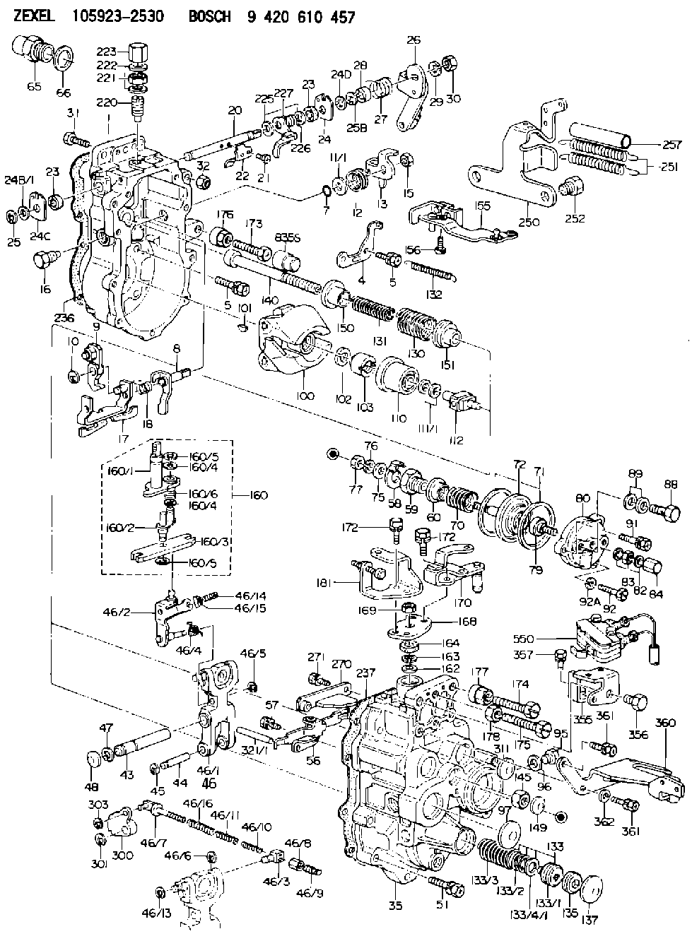
| 1. | [1] | 159360-0820 | GOVERNOR HOUSING |
| 4. | [1] | 159362-5520 | PLATE |
| 5. | [8] | 139006-6100 | BLEEDER SCREW |
| 5. | [8] | 139006-6100 | BLEEDER SCREW |
| 7. | [1] | 139709-0100 | O-RING |
| 8. | [1] | 159364-3720 | LEVER SHAFT |
| 9. | [1] | 159362-5620 | CONTROL LEVER |
| 10. | [1] | 016010-0740 | LOCKING WASHER |
| 11/1. | [0] | 029311-0220 | SHIM D18&10.3T0.2 |
| 11/1. | [0] | 029311-0230 | SHIM D18&10.3T0.5 |
| 11/1. | [0] | 029311-0430 | SHIM D18&10.3T0.30 |
| 11/1. | [0] | 029311-0440 | SHIM D18&10.3T0.40 |
| 11/1. | [0] | 029311-0450 | SHIM D18&10.3T0.25 |
| 11/1. | [0] | 029311-0460 | SHIM D18&10.3T0.35 |
| 11/1. | [0] | 139410-3300 | SHIM D18&10.3T0.6 |
| 11/1. | [0] | 139410-3400 | SHIM D18&10.3T0.8 |
| 11/1. | [0] | 139410-3500 | SHIM D18&10.3T0.9 |
| 12. | [1] | 159368-8000 | COILED SPRING |
| 13. | [1] | 159362-4100 | CONTROL LEVER |
| 15. | [1] | 013020-8040 | UNION NUT M8P1.25H7 |
| 16. | [1] | 159364-5100 | CAPSULE |
| 17. | [1] | 159362-1821 | CONTROL LEVER |
| 18. | [1] | 159368-6800 | COILED SPRING |
| 20. | [1] | 159364-3800 | LEVER SHAFT |
| 21. | [2] | 020104-1240 | BLEEDER SCREW |
| 22. | [1] | 159362-0600 | CONTROL LEVER |
| 23. | [2] | 139608-0600 | PACKING RING |
| 23. | [2] | 139608-0600 | PACKING RING |
| 24. | [1] | 159362-0700 | PLAIN WASHER |
| 24B/1. | [0] | 139408-1000 | SHIM D16&8T0.5 |
| 24B/1. | [0] | 139408-1300 | SHIM D16&8T0.2 |
| 24B/1. | [0] | 139408-1300 | SHIM D16&8T0.2 |
| 24C. | [1] | 159362-0700 | PLAIN WASHER |
| 24D. | [1] | 139308-2100 | PLAIN WASHER |
| 25. | [1] | 159238-4200 | LOCKING WASHER |
| 25B. | [1] | 159238-4200 | LOCKING WASHER |
| 26. | [1] | 159390-5920 | CONTROL LEVER |
| 27. | [1] | 159368-6100 | COILED SPRING |
| 28. | [1] | 159364-6000 | BUSHING |
| 29. | [1] | 014110-8440 | LOCKING WASHER |
| 30. | [1] | 013020-8040 | UNION NUT M8P1.25H7 |
| 31. | [1] | 155644-1301 | BLEEDER SCREW |
| 32. | [1] | 013030-6040 | UNION NUT M6P1H3.6 |
| 35. | [1] | 159361-0320 | GOVERNOR COVER |
| 43. | [1] | 159364-0700 | LEVER SHAFT |
| 44. | [1] | 159364-0800 | BEARING PIN |
| 45. | [2] | 016010-0640 | LOCKING WASHER |
| 46. | [1] | 159362-8420 | TENSIONING LEVER |
| 46/1. | [1] | 159362-8320 | TENSIONING LEVER |
| 46/2. | [1] | 159362-8221 | GUIDE LEVER |
| 46/3. | [1] | 159364-4201 | BEARING PIN |
| 46/4. | [1] | 159368-6201 | COILED SPRING |
| 46/5. | [1] | 016010-0540 | LOCKING WASHER |
| 46/6. | [1] | 016010-0440 | LOCKING WASHER |
| 46/7. | [1] | 159364-4121 | RACK |
| 46/8. | [1] | 159364-4300 | UNION NUT |
| 46/9. | [1] | 159364-4400 | FLAT-HEAD SCREW |
| 46/10. | [1] | 159368-6900 | COILED SPRING |
| 46/11. | [1] | 159368-7000 | COILED SPRING |
| 46/13. | [1] | 016010-0540 | LOCKING WASHER |
| 46/14. | [1] | 159364-1900 | FLAT-HEAD SCREW |
| 46/15. | [1] | 159364-1800 | UNION NUT |
| 46/16. | [1] | 159368-9500 | COILED SPRING |
| 47. | [2] | 016110-1020 | LOCKING WASHER |
| 48. | [2] | 159237-0200 | CAPSULE |
| 51. | [9] | 020106-3840 | BLEEDER SCREW |
| 56. | [1] | 159362-3720 | LEVER GROUP |
| 57. | [2] | 020105-1040 | BLEEDER SCREW M5P0.8L10 |
| 58. | [1] | 146711-0000 | PLATE |
| 59. | [1] | 154413-3600 | BUSHING |
| 60. | [1] | 146716-0000 | UNION NUT |
| 65. | [1] | 155404-3400 | CAP |
| 66. | [1] | 026524-3040 | GASKET |
| 70. | [1] | 154402-4800 | COILED SPRING |
| 71. | [2] | 154413-2600 | GASKET |
| 72. | [1] | 154415-1020 | DIAPHRAGM |
| 75. | [1] | 154415-1100 | SLOTTED WASHER |
| 76. | [1] | 014110-6440 | LOCKING WASHER |
| 77. | [1] | 013030-6010 | UNION NUT |
| 79. | [1] | 154413-4000 | FLAT-HEAD SCREW |
| 80. | [1] | 154404-5000 | COVER |
| 82. | [2] | 026506-1040 | GASKET D9.9&6.2T1 |
| 83. | [1] | 013030-6040 | UNION NUT M6P1H3.6 |
| 84. | [1] | 154035-1600 | CAP NUT |
| 88. | [1] | 029731-0180 | EYE BOLT |
| 89. | [2] | 026510-1340 | GASKET D13.4&10.2T1 |
| 91. | [1] | 020106-2040 | BLEEDER SCREW M6P1L20 |
| 92. | [2] | 139006-7000 | BLEEDER SCREW |
| 92A. | [2] | 014110-6440 | LOCKING WASHER |
| 95. | [1] | 029111-2090 | CAPSULE |
| 96. | [1] | 029331-2130 | GASKET |
| 97. | [1] | 159364-2000 | CAPSULE |
| 100. | [1] | 154100-9220 | FLYWEIGHT ASSEMBLY |
| 101. | [1] | 025803-1310 | WOODRUFF KEY |
| 102. | [1] | 029321-2020 | LOCKING WASHER |
| 103. | [1] | 029231-2030 | UNION NUT |
| 110. | [1] | 154123-2320 | SLIDING PIECE |
| 111/1. | [0] | 029311-0010 | SHIM D14&10.1T0.2 |
| 111/1. | [0] | 029311-0180 | SHIM D14&10.1T0.3 |
| 111/1. | [0] | 029311-0190 | SHIM D14&10.1T0.40 |
| 111/1. | [0] | 029311-0210 | SHIM D14&10.1T1 |
| 111/1. | [0] | 139410-0000 | SHIM D14.0&10.1T0.5 |
| 111/1. | [0] | 139410-0100 | SHIM D14.0&10.1T1.5 |
| 111/1. | [0] | 139410-3000 | SHIM D14&10.1T2.0 |
| 111/1. | [0] | 139410-3100 | SHIM D14&10.1T3.0 |
| 111/1. | [0] | 139410-3200 | SHIM D14&10.1T4.0 |
| 112. | [1] | 159364-5200 | TERMINAL STUD |
| 130. | [1] | 159367-0000 | GOVERNOR SPRING |
| 131. | [1] | 159367-6400 | GOVERNOR SPRING |
| 132. | [1] | 159368-6500 | COILED SPRING |
| 133. | [1] | 159368-2220 | SPRING PACK |
| 133/1. | [1] | 159364-2200 | GUIDE SLEEVE |
| 133/2. | [1] | 159368-0100 | COILED SPRING |
| 133/3. | [1] | 159368-0500 | COILED SPRING |
| 133/4/1. | [0] | 029311-0010 | SHIM D14&10.1T0.2 |
| 133/4/1. | [0] | 029311-0180 | SHIM D14&10.1T0.3 |
| 133/4/1. | [0] | 029311-0190 | SHIM D14&10.1T0.40 |
| 133/4/1. | [0] | 029311-0210 | SHIM D14&10.1T1 |
| 133/4/1. | [0] | 139410-0000 | SHIM D14.0&10.1T0.5 |
| 133/4/1. | [0] | 139410-0000 | SHIM D14.0&10.1T0.5 |
| 133/4/1. | [0] | 139410-0100 | SHIM D14.0&10.1T1.5 |
| 133/4/1. | [0] | 139410-3000 | SHIM D14&10.1T2.0 |
| 133/4/1. | [0] | 139410-3100 | SHIM D14&10.1T3.0 |
| 133/4/1. | [0] | 139410-3200 | SHIM D14&10.1T4.0 |
| 135. | [1] | 159364-2300 | FLAT-HEAD SCREW |
| 137. | [1] | 159364-2000 | CAPSULE |
| 140. | [1] | 159364-2500 | LEVER SHAFT |
| 145. | [1] | 159233-5700 | UNION NUT |
| 149. | [1] | 159237-5400 | CAPSULE |
| 150. | [1] | 159364-2600 | SLOTTED WASHER |
| 151. | [1] | 159364-2700 | SLOTTED WASHER |
| 155. | [1] | 159363-2720 | STRAP |
| 156. | [1] | 010235-1020 | HEX-SOCKET-HEAD CAP SCREW |
| 160. | [1] | 159362-2020 | LEVER GROUP |
| 160/1. | [1] | 159364-3220 | LEVER SHAFT |
| 160/2. | [1] | 159362-1020 | CONTROL LEVER |
| 160/3. | [1] | 159362-2000 | CONTROL LEVER |
| 160/4. | [2] | 159362-1300 | SHIM |
| 160/4. | [2] | 159362-1300 | SHIM |
| 160/5. | [2] | 016010-0840 | LOCKING WASHER |
| 160/5. | [2] | 016010-0840 | LOCKING WASHER |
| 160/6. | [1] | 159368-6600 | COILED SPRING |
| 162. | [1] | 139411-0600 | SHIM |
| 163. | [1] | 159238-3000 | LOCKING WASHER |
| 164. | [1] | 139610-0800 | PACKING RING |
| 168. | [1] | 159380-0300 | CONTROL LEVER |
| 169. | [1] | 013020-8040 | UNION NUT M8P1.25H7 |
| 170. | [1] | 159382-4120 | CONTROL LEVER |
| 172. | [4] | 020106-1240 | BLEEDER SCREW M6P1.0L12 |
| 172. | [4] | 020106-1240 | BLEEDER SCREW M6P1.0L12 |
| 173. | [1] | 154013-1700 | BLEEDER SCREW |
| 173B. | [1] | 154013-1800 | BLEEDER SCREW |
| 173C. | [1] | 154013-1900 | BLEEDER SCREW |
| 174. | [1] | 154013-2000 | BLEEDER SCREW |
| 175. | [1] | 154013-3300 | BLEEDER SCREW |
| 176. | [1] | 154011-4000 | UNION NUT |
| 177. | [1] | 154011-4100 | UNION NUT |
| 178. | [1] | 139210-0400 | UNION NUT |
| 181. | [1] | 159382-4220 | CONTROL LEVER |
| 220. | [1] | 159368-8420 | HEADLESS SCREW |
| 221. | [1] | 154011-4300 | UNION NUT |
| 222. | [2] | 026512-1540 | GASKET D15.4&12.2T1.50 |
| 223. | [1] | 154159-2100 | CAP NUT |
| 225. | [2] | 029310-8050 | SHIM D13.5&8T0.5 |
| 226. | [1] | 159368-9101 | COILED SPRING |
| 227. | [1] | 159362-6720 | CONTROL LEVER |
| 236. | [1] | 154390-4100 | GASKET |
| 237. | [1] | 154390-2500 | GASKET |
| 250. | [1] | 159398-6120 | BRACKET |
| 251. | [2] | 154338-5100 | COILED SPRING |
| 252. | [2] | 010010-1240 | BLEEDER SCREW M10P1.5L12 4T |
| 257. | [2] | 154156-2500 | TUBE |
| 270. | [1] | 159362-4620 | GUIDE PLATE |
| 271. | [2] | 020106-1640 | BLEEDER SCREW M6P1.0L14 |
| 300. | [1] | 159373-4400 | CAM PLATE |
| 301. | [1] | 016010-0840 | LOCKING WASHER |
| 303. | [1] | 016010-0540 | LOCKING WASHER |
| 311. | [2] | 159237-5400 | CAPSULE |
| 321/1. | [1] | 159274-5100 | STOP PIN L72.5 |
| 321/1. | [1] | 159274-5200 | STOP PIN L73 |
| 321/1. | [1] | 159274-5300 | STOP PIN L73.5 |
| 321/1. | [1] | 159274-5400 | STOP PIN L74 |
| 321/1. | [1] | 159274-5500 | STOP PIN L74.5 |
| 321/1. | [1] | 159274-5600 | STOP PIN L75 |
| 321/1. | [1] | 159274-5700 | STOP PIN L75.5 |
| 321/1. | [1] | 159274-5800 | STOP PIN L76 |
| 321/1. | [1] | 159274-5900 | STOP PIN L76.5 |
| 321/1. | [1] | 159274-6000 | STOP PIN L77 |
| 321/1. | [1] | 159274-6100 | STOP PIN L77.5 |
| 321/1. | [1] | 159274-6200 | STOP PIN L78 |
| 321/1. | [1] | 159274-6300 | STOP PIN L78.5 |
| 321/1. | [1] | 159274-6400 | STOP PIN L79 |
| 321/1. | [1] | 159274-6500 | STOP PIN L79.5 |
| 321/1. | [1] | 159274-6600 | STOP PIN L80 |
| 321/1. | [1] | 159274-6700 | STOP PIN L80.5 |
| 321/1. | [1] | 159274-6800 | STOP PIN L81 |
| 321/1. | [1] | 159274-6900 | STOP PIN L81.5 |
| 321/1. | [1] | 159274-7000 | STOP PIN L82 |
| 321/1. | [1] | 159274-7100 | STOP PIN L82.5 |
| 321/1. | [1] | 159274-7200 | STOP PIN L83 |
| 321/1. | [1] | 159274-7300 | STOP PIN L83.5 |
| 321/1. | [1] | 159274-7400 | STOP PIN L84 |
| 321/1. | [1] | 159274-7500 | STOP PIN L84.5 |
| 321/1. | [1] | 159274-7600 | STOP PIN L85 |
| 321/1. | [1] | 159274-7700 | STOP PIN L85.5 |
| 321/1. | [1] | 159274-7800 | STOP PIN L86 |
| 321/1. | [1] | 159274-7900 | STOP PIN L86.5 |
| 321/1. | [1] | 159274-8000 | STOP PIN L87 |
| 321/1. | [1] | 159274-8100 | STOP PIN L87.5 |
| 321/1. | [1] | 159274-8200 | STOP PIN L88 |
| 321/1. | [1] | 159274-8300 | STOP PIN L88.5 |
| 321/1. | [1] | 159274-8400 | STOP PIN L89 |
| 321/1. | [1] | 159274-8500 | STOP PIN L89.5 |
| 321/1. | [1] | 159274-8600 | STOP PIN L90 |
| 355. | [1] | 159395-5600 | BRACKET |
| 356. | [1] | 010110-1640 | BLEEDER SCREW M101.25L16 |
| 357. | [1] | 020106-1240 | BLEEDER SCREW M6P1.0L12 |
| 360. | [1] | 159398-4920 | BRACKET |
| 361. | [3] | 020106-1640 | BLEEDER SCREW M6P1.0L14 |
| 361. | [3] | 020106-1640 | BLEEDER SCREW M6P1.0L14 |
| 362. | [2] | 154604-4500 | PLAIN WASHER |
| 550. | [1] | 153146-3220 | MICROSWITCH |
Include in #1:
106673-7560
as GOVERNOR
Cross reference number
Zexel num
Bosch num
Firm num
Name
Information:
Start By:a. remove timing gear coverb. remove push rods and valve lifters 1. Remove air compressor outlet hose (1). (Not applicable).2. Remove air compressor air inlet tube (3). (Not applicable).3. Remove air compressor coolant outlet tube (4). (Not applicable)4. Remove turbocharger oil return tube (2). 5. Use Tooling (A) to remove studs (5).6. Turn the flywheel with Tool (B), and remove each bolt (6) as it becomes accessible.7. Turn the flywheel with Tool (B) until the "V" marks on the front timing gears are in alignment.8. Install Tooling (C) through the holes for studs (5) into camshaft rear gear (7).
Tooling (C) must be used to prevent the loss of rear balance weight timing and to keep the camshaft rear gear in place when the camshaft is removed.
9. Tighten Tooling (C) evenly to remove the camshaft rear gear from the camshaft. 10. Remove thrust plate (8).
Be careful not to damage the camshaft bearings. Do not pry the camshaft out of the cylinder block. If resistance to camshaft removal occurs, turn the camshaft so the lobes will align the bearing journals with the camshaft bearing bores.
11. Carefully remove the camshaft and gear (9) from the cylinder block.12. If removal of the camshaft gear is necessary, place the camshaft and gear in a hydraulic press. Place Tool (D) over the camshaft, and press against it to remove the camshaft from the gear.
Be careful not to scratch or mar the finished surfaces of the camshaft.
13. Remove the key from the camshaft.14. If dowel removal is necessary, use Tool (E) to remove the dowel.Install Camshaft
1. Install the key in the camshaft. Be sure the key is seated in the camshaft.2. Install the pin in the rear of the camshaft. Install the pin to a height of 8.51 to 9.01 mm (.335 to .355 in).3. Heat the camshaft drive gear to a maximum temperature of 204° C (400° F), align the groove in the drive gear with the key in the camshaft, and install the camshaft drive gear with the timing marks away from the camshaft.4. Put clean engine oil on the camshaft bearing journals and lobes.5. Carefully install the camshaft into the cylinder block. Do not force the camshaft into position. If resistance to camshaft installation occurs, turn the camshaft so the lobes will align the bearing journals with the camshaft bearing bores. 6. Align the "V" marks on camshaft drive gear (2) and idler gear (3).7. Install thrust plate (1) to hold the camshaft and camshaft drive gear (2) in the cylinder block. 8. Loosen the bolts Tool (B) that hold camshaft rear gear (5) so camshaft rear gear (5) will engage the dowel on the rear of the camshaft.9. After the dowel is engaged, remove Tool (B), and install bolts (4).10. Use Tool (A) to turn the flywheel, and install each of four bolts (4). Tighten bolts (4) to a torque of 23 to 31 N m (17 to 23 lb ft).11. Put 5P-3413 Pipe Sealant with "Teflon" on the