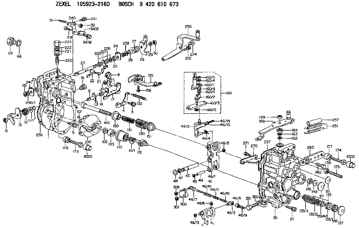
Information governor
BOSCH
9 420 610 673
9420610673
ZEXEL
105923-2160
1059232160
HINO
223008720A
223008720a

Rating:
Scheme ###:
| 1. | [1] | 159360-0420 | GOVERNOR HOUSING |
| 4. | [1] | 159362-5520 | PLATE |
| 5. | [8] | 139006-6100 | BLEEDER SCREW |
| 5. | [8] | 139006-6100 | BLEEDER SCREW |
| 7. | [1] | 139709-0100 | O-RING |
| 8. | [1] | 159364-0120 | LEVER SHAFT |
| 9. | [1] | 159362-5620 | CONTROL LEVER |
| 10. | [1] | 016010-0740 | LOCKING WASHER |
| 11/1. | [0] | 029311-0220 | SHIM D18&10.3T0.2 |
| 11/1. | [0] | 029311-0230 | SHIM D18&10.3T0.5 |
| 11/1. | [0] | 029311-0430 | SHIM D18&10.3T0.30 |
| 11/1. | [0] | 029311-0440 | SHIM D18&10.3T0.40 |
| 11/1. | [0] | 029311-0450 | SHIM D18&10.3T0.25 |
| 11/1. | [0] | 029311-0460 | SHIM D18&10.3T0.35 |
| 11/1. | [0] | 139410-3300 | SHIM D18&10.3T0.6 |
| 11/1. | [0] | 139410-3400 | SHIM D18&10.3T0.8 |
| 11/1. | [0] | 139410-3500 | SHIM D18&10.3T0.9 |
| 12. | [1] | 159368-7800 | COILED SPRING |
| 13. | [1] | 159362-1500 | CONTROL LEVER |
| 15. | [1] | 013020-8040 | UNION NUT M8P1.25H7 |
| 16. | [1] | 159364-5000 | CAPSULE |
| 17. | [1] | 159362-0520 | CONTROL LEVER |
| 18. | [1] | 159215-0600 | COILED SPRING |
| 20. | [1] | 159364-3800 | LEVER SHAFT |
| 21. | [2] | 020104-1240 | BLEEDER SCREW |
| 22. | [1] | 159362-0600 | CONTROL LEVER |
| 23. | [2] | 139608-0600 | PACKING RING |
| 23. | [2] | 139608-0600 | PACKING RING |
| 24. | [1] | 159362-0700 | PLAIN WASHER |
| 24B. | [1] | 139308-2100 | PLAIN WASHER |
| 24C. | [1] | 159362-0700 | PLAIN WASHER |
| 25. | [1] | 159238-4200 | LOCKING WASHER |
| 25B. | [1] | 159238-4200 | LOCKING WASHER |
| 26. | [1] | 159390-4300 | CONTROL LEVER |
| 27. | [1] | 159368-6100 | COILED SPRING |
| 28. | [1] | 159364-6000 | BUSHING |
| 29. | [1] | 014110-8440 | LOCKING WASHER |
| 30. | [1] | 013020-8040 | UNION NUT M8P1.25H7 |
| 31. | [1] | 155615-1100 | FLAT-HEAD SCREW M6P1.0L37 |
| 31B. | [1] | 153505-0800 | FLAT-HEAD SCREW |
| 32. | [2] | 013030-6040 | UNION NUT M6P1H3.6 |
| 35. | [1] | 159361-0520 | GOVERNOR COVER |
| 43. | [1] | 159364-0700 | LEVER SHAFT |
| 44. | [1] | 159364-0800 | BEARING PIN |
| 45. | [2] | 016010-0640 | LOCKING WASHER |
| 46. | [1] | 159363-5720 | TENSIONING LEVER |
| 46/1. | [1] | 159363-5620 | TENSIONING LEVER |
| 46/2. | [1] | 159362-8221 | GUIDE LEVER |
| 46/3. | [1] | 159364-4201 | BEARING PIN |
| 46/4. | [1] | 159368-6201 | COILED SPRING |
| 46/5. | [1] | 016010-0540 | LOCKING WASHER |
| 46/6. | [1] | 016010-0440 | LOCKING WASHER |
| 46/7. | [1] | 159364-4121 | RACK |
| 46/8. | [1] | 159364-4300 | UNION NUT |
| 46/9. | [1] | 159364-4400 | FLAT-HEAD SCREW |
| 46/10. | [1] | 159368-6900 | COILED SPRING |
| 46/11. | [1] | 159368-7000 | COILED SPRING |
| 46/13. | [1] | 016010-0540 | LOCKING WASHER |
| 46/14. | [1] | 159364-1900 | FLAT-HEAD SCREW |
| 46/15. | [1] | 159364-1800 | UNION NUT |
| 46/16. | [1] | 159368-9500 | COILED SPRING |
| 47. | [2] | 016110-1020 | LOCKING WASHER |
| 48. | [2] | 159237-0200 | CAPSULE |
| 51. | [9] | 020106-3840 | BLEEDER SCREW |
| 65. | [1] | 155404-1700 | CAP |
| 66. | [1] | 026524-3040 | GASKET |
| 97. | [1] | 159364-2000 | CAPSULE |
| 100. | [1] | 154100-9220 | FLYWEIGHT ASSEMBLY |
| 101. | [1] | 025803-1310 | WOODRUFF KEY |
| 102. | [1] | 029321-2020 | LOCKING WASHER |
| 103. | [1] | 029231-2030 | UNION NUT |
| 110. | [1] | 154123-2320 | SLIDING PIECE |
| 111/1. | [0] | 029311-0010 | SHIM D14&10.1T0.2 |
| 111/1. | [0] | 029311-0180 | SHIM D14&10.1T0.3 |
| 111/1. | [0] | 029311-0190 | SHIM D14&10.1T0.40 |
| 111/1. | [0] | 029311-0210 | SHIM D14&10.1T1 |
| 111/1. | [0] | 139410-0000 | SHIM D14.0&10.1T0.5 |
| 111/1. | [0] | 139410-0100 | SHIM D14.0&10.1T1.5 |
| 111/1. | [0] | 139410-3000 | SHIM D14&10.1T2.0 |
| 111/1. | [0] | 139410-3100 | SHIM D14&10.1T3.0 |
| 111/1. | [0] | 139410-3200 | SHIM D14&10.1T4.0 |
| 112. | [1] | 159364-2100 | TERMINAL STUD |
| 130. | [1] | 159367-0800 | GOVERNOR SPRING |
| 131. | [1] | 159367-6300 | GOVERNOR SPRING |
| 132. | [1] | 159369-0100 | COILED SPRING |
| 133. | [1] | 159368-3920 | SPRING PACK |
| 133/1. | [1] | 159364-2200 | GUIDE SLEEVE |
| 133/2. | [1] | 159368-1400 | COILED SPRING |
| 133/3. | [1] | 159368-0600 | COILED SPRING |
| 133/4/1. | [0] | 029311-0010 | SHIM D14&10.1T0.2 |
| 133/4/1. | [0] | 029311-0180 | SHIM D14&10.1T0.3 |
| 133/4/1. | [0] | 029311-0190 | SHIM D14&10.1T0.40 |
| 133/4/1. | [0] | 029311-0210 | SHIM D14&10.1T1 |
| 133/4/1. | [0] | 139410-0000 | SHIM D14.0&10.1T0.5 |
| 133/4/1. | [0] | 139410-0100 | SHIM D14.0&10.1T1.5 |
| 133/4/1. | [0] | 139410-3000 | SHIM D14&10.1T2.0 |
| 133/4/1. | [0] | 139410-3100 | SHIM D14&10.1T3.0 |
| 133/4/1. | [0] | 139410-3200 | SHIM D14&10.1T4.0 |
| 135. | [1] | 159364-2300 | FLAT-HEAD SCREW |
| 137. | [1] | 159364-2000 | CAPSULE |
| 140. | [1] | 159364-2500 | LEVER SHAFT |
| 145. | [1] | 159233-5700 | UNION NUT |
| 149. | [1] | 159237-5400 | CAPSULE |
| 150. | [1] | 159364-2600 | SLOTTED WASHER |
| 151. | [1] | 159364-2700 | SLOTTED WASHER |
| 155. | [1] | 159363-2621 | STRAP |
| 156. | [1] | 010235-1020 | HEX-SOCKET-HEAD CAP SCREW |
| 160. | [1] | 159362-5820 | LEVER GROUP |
| 160/1. | [1] | 159364-6520 | LEVER SHAFT |
| 160/2. | [1] | 159362-5921 | CONTROL LEVER |
| 160/3. | [1] | 159362-2000 | CONTROL LEVER |
| 160/4. | [2] | 159362-1300 | SHIM |
| 160/4. | [2] | 159362-1300 | SHIM |
| 160/5. | [2] | 016010-0840 | LOCKING WASHER |
| 160/5. | [2] | 016010-0840 | LOCKING WASHER |
| 160/6. | [1] | 159368-8600 | COILED SPRING |
| 162. | [1] | 139411-0600 | SHIM |
| 163. | [1] | 159238-3000 | LOCKING WASHER |
| 164. | [1] | 139610-0800 | PACKING RING |
| 168. | [1] | 159381-1520 | CONTROL LEVER |
| 169. | [1] | 013020-8040 | UNION NUT M8P1.25H7 |
| 173. | [1] | 154013-1700 | BLEEDER SCREW |
| 173B. | [1] | 154013-1800 | BLEEDER SCREW |
| 173C. | [1] | 154013-1900 | BLEEDER SCREW |
| 174. | [1] | 154013-2000 | BLEEDER SCREW |
| 174B. | [1] | 154013-5300 | BLEEDER SCREW |
| 175. | [1] | 154013-3000 | FLAT-HEAD SCREW |
| 176. | [1] | 154011-4000 | UNION NUT |
| 177. | [1] | 154011-4100 | UNION NUT |
| 178. | [1] | 013131-0040 | UNION NUT M10P1.25H6 |
| 220. | [1] | 159368-8420 | HEADLESS SCREW |
| 221. | [1] | 154011-4300 | UNION NUT |
| 222. | [2] | 026512-1540 | GASKET D15.4&12.2T1.50 |
| 223. | [1] | 154159-2100 | CAP NUT |
| 225. | [2] | 029310-8050 | SHIM D13.5&8T0.5 |
| 226. | [1] | 159368-9101 | COILED SPRING |
| 227. | [1] | 159362-6720 | CONTROL LEVER |
| 236. | [1] | 154390-4100 | GASKET |
| 237. | [1] | 154390-2500 | GASKET |
| 250. | [1] | 159397-3120 | BRACKET |
| 251. | [2] | 154338-7800 | COILED SPRING |
| 252. | [1] | 020106-1240 | BLEEDER SCREW M6P1.0L12 |
| 254. | [1] | 010010-1240 | BLEEDER SCREW M10P1.5L12 4T |
| 257. | [2] | 154156-0900 | TUBE |
| 260. | [1] | 159395-0600 | BRACKET |
| 262. | [2] | 139010-1100 | BLEEDER SCREW |
| 270. | [1] | 159362-6820 | GUIDE PLATE |
| 271. | [2] | 020106-1640 | BLEEDER SCREW M6P1.0L14 |
| 300. | [1] | 159373-7000 | CAM PLATE |
| 301. | [1] | 016010-0840 | LOCKING WASHER |
| 303. | [1] | 016010-0540 | LOCKING WASHER |
| 311. | [2] | 159237-5400 | CAPSULE |
| 340. | [1] | 159397-0420 | BRACKET |
| 340B. | [1] | 159397-0500 | PLATE |
| 341. | [1] | 020106-1240 | BLEEDER SCREW M6P1.0L12 |
| 341B. | [1] | 020106-1840 | BLEEDER SCREW M6P1L18 |
| 350. | [1] | 139512-0700 | GASKET |
| 351. | [1] | 139812-3201 | EYE BOLT |
Cross reference number
Zexel num
Bosch num
Firm num
Name
Information:
There are two water temperature regulators, one for each cylinder head.1. Drain the coolant from the engine to a level below the water temperature regulators.
Typical Example2. Remove elbow (1). Remove tube and elbow (2). 3. Remove cover assemblies (3). 4. Remove water temperature regulator (4) from each cover assembly. 5. Remove lip-type seal (5) from each cover assembly if a replacement is necessary.6. Check the water temperature regulators. See Specifications Manual SENR6475. The following steps are for the installation of the water temperature regulators. 7. Use Tool (A) to install lip-type seals (5). Install the seals with the lip toward the inside of the covers. Install the seal until it contacts the counterbore in the cover assembly.
If the water temperature regulators are installed incorrectly the engine will over heat.
8. Put clean glycerin on the lip of seal (5), and install water temperature regulator (4) in each cover assembly (3). 9. Install new gaskets (6) and cover assemblies (3).
Typical Example10. Install the gaskets and elbow (1). Put clean engine oil or glycerin on the O-ring seals on tube (2). Install the gasket, tube and elbow (2).11. Fill the cooling system to the correct level. See the Operation & Maintenance Manual.