Information governor
BOSCH
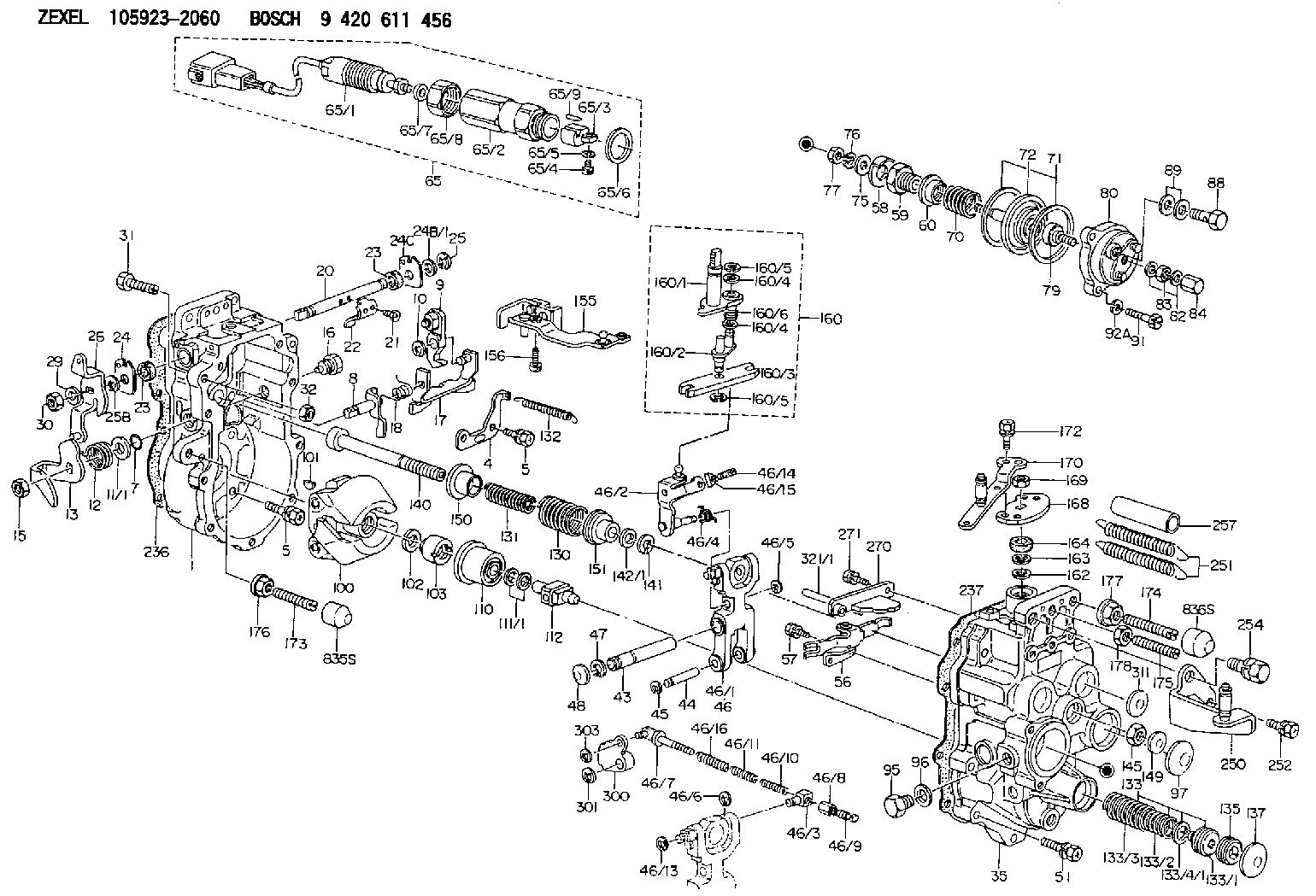
9 420 611 456
9420611456
ZEXEL
105923-2060
1059232060
NISSAN-DIESEL
19101Z6604
19101z6604
Rating:
Scheme ###:
| 1. | [1] | 159360-0020 | GOVERNOR HOUSING |
| 4. | [1] | 159362-5520 | PLATE |
| 5. | [10] | 139006-6100 | BLEEDER SCREW |
| 5. | [10] | 139006-6100 | BLEEDER SCREW |
| 7. | [1] | 139709-0100 | O-RING |
| 8. | [1] | 159364-0120 | LEVER SHAFT |
| 9. | [1] | 159362-5720 | CONTROL LEVER |
| 10. | [1] | 016010-0740 | LOCKING WASHER |
| 11/1. | [0] | 029311-0220 | SHIM D18&10.3T0.2 |
| 11/1. | [0] | 029311-0230 | SHIM D18&10.3T0.5 |
| 11/1. | [0] | 029311-0430 | SHIM D18&10.3T0.30 |
| 11/1. | [0] | 029311-0440 | SHIM D18&10.3T0.40 |
| 11/1. | [0] | 029311-0450 | SHIM D18&10.3T0.25 |
| 11/1. | [0] | 029311-0460 | SHIM D18&10.3T0.35 |
| 11/1. | [0] | 139410-3300 | SHIM D18&10.3T0.6 |
| 11/1. | [0] | 139410-3400 | SHIM D18&10.3T0.8 |
| 11/1. | [0] | 139410-3500 | SHIM D18&10.3T0.9 |
| 12. | [1] | 159368-7800 | COILED SPRING |
| 13. | [1] | 159362-0400 | CONTROL LEVER |
| 15. | [1] | 013020-8040 | UNION NUT M8P1.25H7 |
| 16. | [1] | 159364-5000 | CAPSULE |
| 17. | [1] | 159362-2820 | CONTROL LEVER |
| 18. | [1] | 159215-0600 | COILED SPRING |
| 20. | [1] | 159364-0300 | LEVER SHAFT |
| 21. | [2] | 020104-1240 | BLEEDER SCREW |
| 22. | [1] | 159362-0600 | CONTROL LEVER |
| 23. | [2] | 139608-0600 | PACKING RING |
| 23. | [2] | 139608-0600 | PACKING RING |
| 24. | [1] | 159362-0700 | PLAIN WASHER |
| 24B/1. | [0] | 139408-1000 | SHIM D16&8T0.5 |
| 24B/1. | [0] | 139408-1300 | SHIM D16&8T0.2 |
| 24C. | [1] | 159362-0700 | PLAIN WASHER |
| 25. | [1] | 159238-4200 | LOCKING WASHER |
| 25B. | [1] | 159238-4200 | LOCKING WASHER |
| 26. | [1] | 159390-1620 | CONTROL LEVER |
| 29. | [1] | 014110-8440 | LOCKING WASHER |
| 30. | [1] | 013020-8040 | UNION NUT M8P1.25H7 |
| 31. | [1] | 155644-1301 | BLEEDER SCREW |
| 32. | [1] | 013030-6040 | UNION NUT M6P1H3.6 |
| 35. | [1] | 159361-0220 | GOVERNOR COVER |
| 43. | [1] | 159364-0700 | LEVER SHAFT |
| 44. | [1] | 159364-0800 | BEARING PIN |
| 45. | [2] | 016010-0640 | LOCKING WASHER |
| 46. | [1] | 159362-8420 | TENSIONING LEVER |
| 46/1. | [1] | 159362-8320 | TENSIONING LEVER |
| 46/2. | [1] | 159362-8221 | GUIDE LEVER |
| 46/3. | [1] | 159364-4201 | BEARING PIN |
| 46/4. | [1] | 159368-6201 | COILED SPRING |
| 46/5. | [1] | 016010-0540 | LOCKING WASHER |
| 46/6. | [1] | 016010-0440 | LOCKING WASHER |
| 46/7. | [1] | 159364-4121 | RACK |
| 46/8. | [1] | 159364-4300 | UNION NUT |
| 46/9. | [1] | 159364-4400 | FLAT-HEAD SCREW |
| 46/10. | [1] | 159368-6900 | COILED SPRING |
| 46/11. | [1] | 159368-7000 | COILED SPRING |
| 46/13. | [1] | 016010-0540 | LOCKING WASHER |
| 46/14. | [1] | 159364-1900 | FLAT-HEAD SCREW |
| 46/15. | [1] | 159364-1800 | UNION NUT |
| 46/16. | [1] | 159368-9500 | COILED SPRING |
| 47. | [2] | 016110-1020 | LOCKING WASHER |
| 48. | [2] | 159237-0200 | CAPSULE |
| 51. | [9] | 020106-3840 | BLEEDER SCREW |
| 56. | [1] | 159362-3220 | LEVER GROUP |
| 57. | [2] | 020105-1040 | BLEEDER SCREW M5P0.8L10 |
| 58. | [1] | 146711-0000 | PLATE |
| 59. | [1] | 154413-3600 | BUSHING |
| 60. | [1] | 146716-0000 | UNION NUT |
| 65. | [1] | 154610-9420 | RACK SENSOR ASSY |
| 65/1. | [1] | 479742-7820 | RACK SENSOR |
| 65/2. | [1] | 154614-2500 | JOINT CONNECTION |
| 65/3. | [1] | 154614-3200 | BLOCK |
| 65/4. | [1] | 010234-1040 | HEX-SOCKET-HEAD CAP SCREW |
| 65/5. | [1] | 014110-4440 | LOCKING WASHER |
| 65/6. | [1] | 026524-3040 | GASKET |
| 65/7. | [1] | 029310-6280 | SHIM D11.5&6.4T1.50 |
| 65/8. | [1] | 154614-1900 | UNION NUT |
| 65/9. | [1] | 154614-3300 | BEARING PIN |
| 70. | [1] | 154403-0200 | COILED SPRING |
| 71. | [2] | 154413-2600 | GASKET |
| 72. | [1] | 154415-1020 | DIAPHRAGM |
| 75. | [1] | 154415-1100 | SLOTTED WASHER |
| 76. | [1] | 014110-6440 | LOCKING WASHER |
| 77. | [1] | 013030-6010 | UNION NUT |
| 79. | [1] | 154413-4000 | FLAT-HEAD SCREW |
| 80. | [1] | 154404-5600 | COVER |
| 82. | [2] | 026506-1040 | GASKET D9.9&6.2T1 |
| 83. | [1] | 013030-6040 | UNION NUT M6P1H3.6 |
| 84. | [1] | 154035-1600 | CAP NUT |
| 88. | [1] | 029731-0180 | EYE BOLT |
| 89. | [2] | 026510-1340 | GASKET D13.4&10.2T1 |
| 91. | [3] | 154062-2900 | BLEEDER SCREW |
| 92A. | [3] | 014110-6440 | LOCKING WASHER |
| 95. | [1] | 029111-2090 | CAPSULE |
| 96. | [1] | 029331-2130 | GASKET |
| 97. | [1] | 159364-2000 | CAPSULE |
| 100. | [1] | 154101-0920 | FLYWEIGHT ASSEMBLY |
| 101. | [1] | 025803-1310 | WOODRUFF KEY |
| 102. | [1] | 029321-2020 | LOCKING WASHER |
| 103. | [1] | 029231-2030 | UNION NUT |
| 110. | [1] | 154123-2320 | SLIDING PIECE |
| 111/1. | [0] | 029311-0010 | SHIM D14&10.1T0.2 |
| 111/1. | [0] | 029311-0180 | SHIM D14&10.1T0.3 |
| 111/1. | [0] | 029311-0190 | SHIM D14&10.1T0.40 |
| 111/1. | [0] | 029311-0210 | SHIM D14&10.1T1 |
| 111/1. | [0] | 139410-0000 | SHIM D14.0&10.1T0.5 |
| 111/1. | [0] | 139410-0100 | SHIM D14.0&10.1T1.5 |
| 111/1. | [0] | 139410-3000 | SHIM D14&10.1T2.0 |
| 111/1. | [0] | 139410-3100 | SHIM D14&10.1T3.0 |
| 111/1. | [0] | 139410-3200 | SHIM D14&10.1T4.0 |
| 112. | [1] | 159364-2100 | TERMINAL STUD |
| 130. | [1] | 159367-1200 | GOVERNOR SPRING |
| 131. | [1] | 159367-6300 | GOVERNOR SPRING |
| 132. | [1] | 159368-6500 | COILED SPRING |
| 133. | [1] | 159368-2120 | SPRING PACK |
| 133/1. | [1] | 159364-2200 | GUIDE SLEEVE |
| 133/2. | [1] | 159368-0100 | COILED SPRING |
| 133/3. | [1] | 159368-0400 | COILED SPRING |
| 133/4/1. | [0] | 029311-0010 | SHIM D14&10.1T0.2 |
| 133/4/1. | [0] | 029311-0180 | SHIM D14&10.1T0.3 |
| 133/4/1. | [0] | 029311-0190 | SHIM D14&10.1T0.40 |
| 133/4/1. | [0] | 029311-0210 | SHIM D14&10.1T1 |
| 133/4/1. | [0] | 139410-0000 | SHIM D14.0&10.1T0.5 |
| 133/4/1. | [0] | 139410-0100 | SHIM D14.0&10.1T1.5 |
| 133/4/1. | [0] | 139410-3000 | SHIM D14&10.1T2.0 |
| 133/4/1. | [0] | 139410-3100 | SHIM D14&10.1T3.0 |
| 133/4/1. | [0] | 139410-3200 | SHIM D14&10.1T4.0 |
| 135. | [1] | 159364-2300 | FLAT-HEAD SCREW |
| 137. | [1] | 159364-2000 | CAPSULE |
| 140. | [1] | 159364-2500 | LEVER SHAFT |
| 141. | [1] | 016010-0840 | LOCKING WASHER |
| 142/1. | [0] | 029311-0010 | SHIM D14&10.1T0.2 |
| 142/1. | [0] | 029311-0180 | SHIM D14&10.1T0.3 |
| 142/1. | [0] | 029311-0190 | SHIM D14&10.1T0.40 |
| 142/1. | [0] | 029311-0210 | SHIM D14&10.1T1 |
| 142/1. | [0] | 139410-0000 | SHIM D14.0&10.1T0.5 |
| 142/1. | [0] | 139410-0100 | SHIM D14.0&10.1T1.5 |
| 142/1. | [0] | 139410-3000 | SHIM D14&10.1T2.0 |
| 142/1. | [0] | 139410-3100 | SHIM D14&10.1T3.0 |
| 142/1. | [0] | 139410-3200 | SHIM D14&10.1T4.0 |
| 145. | [1] | 159233-5700 | UNION NUT |
| 149. | [1] | 159237-5400 | CAPSULE |
| 150. | [1] | 159364-2600 | SLOTTED WASHER |
| 151. | [1] | 159364-2700 | SLOTTED WASHER |
| 155. | [1] | 159363-2720 | STRAP |
| 156. | [1] | 010235-1020 | HEX-SOCKET-HEAD CAP SCREW |
| 160. | [1] | 159362-2020 | LEVER GROUP |
| 160/1. | [1] | 159364-3220 | LEVER SHAFT |
| 160/2. | [1] | 159362-1020 | CONTROL LEVER |
| 160/3. | [1] | 159362-2000 | CONTROL LEVER |
| 160/4. | [2] | 159362-1300 | SHIM |
| 160/4. | [2] | 159362-1300 | SHIM |
| 160/5. | [2] | 016010-0840 | LOCKING WASHER |
| 160/5. | [2] | 016010-0840 | LOCKING WASHER |
| 160/6. | [1] | 159368-6600 | COILED SPRING |
| 162. | [1] | 139411-0600 | SHIM |
| 163. | [1] | 159238-3000 | LOCKING WASHER |
| 164. | [1] | 139610-0800 | PACKING RING |
| 168. | [1] | 159380-0300 | CONTROL LEVER |
| 169. | [1] | 013020-8040 | UNION NUT M8P1.25H7 |
| 170. | [1] | 159380-4220 | CONTROL LEVER |
| 172. | [2] | 020106-1240 | BLEEDER SCREW M6P1.0L12 |
| 173. | [1] | 154013-3800 | FLAT-HEAD SCREW |
| 173B. | [1] | 154013-4600 | FLAT-HEAD SCREW |
| 174. | [1] | 154013-3700 | FLAT-HEAD SCREW |
| 174B. | [1] | 154013-4700 | FLAT-HEAD SCREW |
| 175. | [1] | 154013-2800 | FLAT-HEAD SCREW |
| 176. | [1] | 154011-4800 | UNION NUT |
| 177. | [1] | 154011-4700 | UNION NUT |
| 178. | [1] | 013131-0040 | UNION NUT M10P1.25H6 |
| 236. | [1] | 154390-4200 | GASKET |
| 237. | [1] | 154390-2500 | GASKET |
| 250. | [1] | 159395-5820 | BRACKET |
| 251. | [1] | 154338-1800 | COILED SPRING |
| 252. | [2] | 020106-1440 | BLEEDER SCREW M6P1.0L14 |
| 254. | [1] | 020010-2040 | BLEEDER SCREW M10P1.25L20 |
| 257. | [1] | 154156-2700 | TUBE |
| 270. | [1] | 159362-2120 | GUIDE PLATE |
| 271. | [2] | 020106-1640 | BLEEDER SCREW M6P1.0L14 |
| 300. | [1] | 159371-5700 | CAM PLATE |
| 301. | [1] | 016010-0840 | LOCKING WASHER |
| 303. | [1] | 016010-0540 | LOCKING WASHER |
| 311. | [2] | 159237-5400 | CAPSULE |
| 321/1. | [1] | 159274-5100 | STOP PIN L72.5 |
| 321/1. | [1] | 159274-5200 | STOP PIN L73 |
| 321/1. | [1] | 159274-5300 | STOP PIN L73.5 |
| 321/1. | [1] | 159274-5400 | STOP PIN L74 |
| 321/1. | [1] | 159274-5500 | STOP PIN L74.5 |
| 321/1. | [1] | 159274-5600 | STOP PIN L75 |
| 321/1. | [1] | 159274-5700 | STOP PIN L75.5 |
| 321/1. | [1] | 159274-5800 | STOP PIN L76 |
| 321/1. | [1] | 159274-5900 | STOP PIN L76.5 |
| 321/1. | [1] | 159274-6000 | STOP PIN L77 |
| 321/1. | [1] | 159274-6100 | STOP PIN L77.5 |
| 321/1. | [1] | 159274-6200 | STOP PIN L78 |
| 321/1. | [1] | 159274-6300 | STOP PIN L78.5 |
| 321/1. | [1] | 159274-6400 | STOP PIN L79 |
| 321/1. | [1] | 159274-6500 | STOP PIN L79.5 |
| 321/1. | [1] | 159274-6600 | STOP PIN L80 |
| 321/1. | [1] | 159274-6700 | STOP PIN L80.5 |
| 321/1. | [1] | 159274-6800 | STOP PIN L81 |
| 321/1. | [1] | 159274-6900 | STOP PIN L81.5 |
| 321/1. | [1] | 159274-7000 | STOP PIN L82 |
| 321/1. | [1] | 159274-7100 | STOP PIN L82.5 |
| 321/1. | [1] | 159274-7200 | STOP PIN L83 |
| 321/1. | [1] | 159274-7300 | STOP PIN L83.5 |
| 321/1. | [1] | 159274-7400 | STOP PIN L84 |
| 321/1. | [1] | 159274-7500 | STOP PIN L84.5 |
| 321/1. | [1] | 159274-7600 | STOP PIN L85 |
| 321/1. | [1] | 159274-7700 | STOP PIN L85.5 |
| 321/1. | [1] | 159274-7800 | STOP PIN L86 |
| 321/1. | [1] | 159274-7900 | STOP PIN L86.5 |
| 321/1. | [1] | 159274-8000 | STOP PIN L87 |
| 321/1. | [1] | 159274-8100 | STOP PIN L87.5 |
| 321/1. | [1] | 159274-8200 | STOP PIN L88 |
| 321/1. | [1] | 159274-8300 | STOP PIN L88.5 |
| 321/1. | [1] | 159274-8400 | STOP PIN L89 |
| 321/1. | [1] | 159274-8500 | STOP PIN L89.5 |
| 321/1. | [1] | 159274-8600 | STOP PIN L90 |
Include in #1:
107692-0810
as GOVERNOR
Cross reference number
Zexel num
Bosch num
Firm num
Name
9 420 611 456
19101Z6604 NISSAN-DIESEL
GOVERNOR
* K 14JG GOV RLD-J(TICS) GOV
* K 14JG GOV RLD-J(TICS) GOV
9 420 611 456
19261Z9003 NISSAN-DIESEL
GOVERNOR
A * K 14JG GOV RLD-J(TICS) GOV
A * K 14JG GOV RLD-J(TICS) GOV
Information:
Start By:a. remove timing gear cover1. Time the engine as follows:a. Install Tool (A) in the flywheel housing.b. Remove the cover from the side of the fuel injection pump housing so the timing pin can be installed. Remove the plug from the flywheel housing so the timing bolt can be installed.c. Turn the engine in the direction of engine rotation until Tool (B) can be installed in fuel injection pump housing and located in the groove in the fuel injection pump camshaft, a 3/8" - 16 NC bolt can be installed in the flywheel through the hole in the flywheel housing, and the "C" marks on the crankshaft gear and the camshaft gear are in alignment with each other. 2. Loosen bolt (1) until there is approximately 3.18 mm (.125 in) gap between washer (2) and fuel pump drive gear (3).3. Install Tool (C) as shown, and loosen the fuel pump drive gear from the taper on the fuel injection pump camshaft. Remove Tool (C), the bolt, washer and fuel pump drive gear.4. Remove the bolts and plate (4) that hold idler gear (5) in position. Remove the idler gear. If necessary, remove the bearing from the idler gear with Tool (D) and a press.
Do not turn the crankshaft after camshaft gear (6) has been removed. Turning the crankshaft will cause damage to the valves.
5. Remove the four bolts that hold camshaft gear (6) to the camshaft. Remove the camshaft gear.Install Timing Gears
1. Make an alignment of the "C" marks on crankshaft gear (3) and camshaft gear (4). Install the camshaft gear and the bolts that hold it. Tighten the bolts to a torque of 55 7 N m (41 5 lb ft).2. Install the bearing in idler gear (1) with Tool (A). The end of the bearing must be 1.52 mm (.060 in) below the face of the gear hub after installation.3. Be sure the oil hole in the shaft for idler gear (1) is open. Put idler gear (1) and plate (2) in position on the shaft. Install the bolts that hold them. 4. Make sure Tool (C) is in position in the groove of the fuel injection pump camshaft.5. Put fuel injection pump drive gear (5) in position on the fuel injection pump camshaft. Put washer (6) in position on the gear with the largest diameter toward the front of the engine. Install bolt (7), and tighten it to a torque of 7 N m (5 lb ft). Make sure bolt (7) does not turn while the flywheel is being turned.6. Remove the timing bolt from the flywheel, and use Tool (B) to turn the flywheel in the opposite direction of engine rotation. Turn the flywheel until the "C" mark on the crankshaft gear moves 30°.7. Turn the flywheel in the direction of engine rotation until the timing bolt can be installed in the flywheel and the "C" marks are in alignment. This will remove all of the backlash from the timing gears.8.