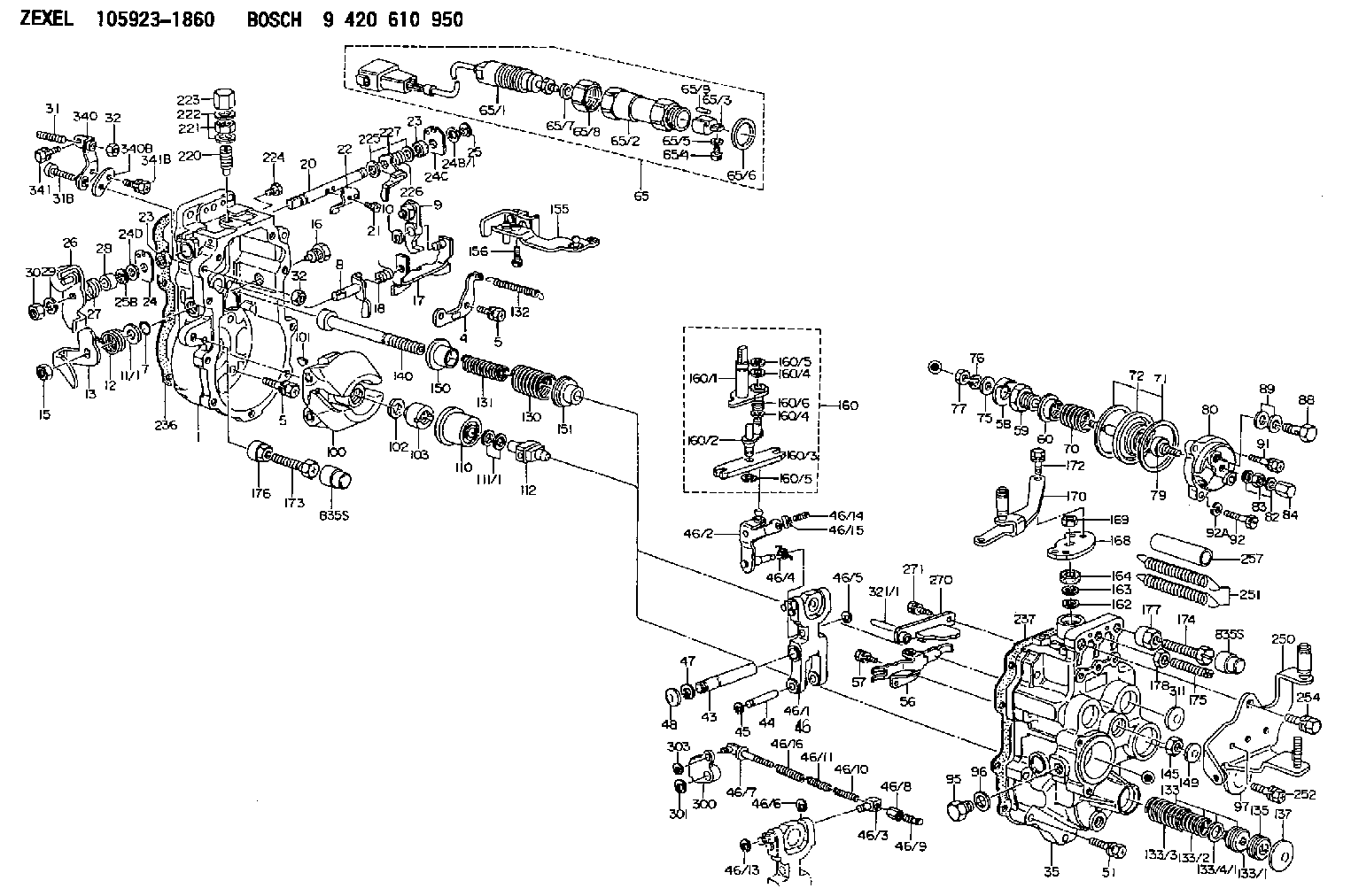
Information governor
BOSCH
9 420 610 950
9420610950
ZEXEL
105923-1860
1059231860
HINO
223008610A
223008610a

Rating:
Scheme ###:
| 1. | [1] | 159360-0520 | GOVERNOR HOUSING |
| 4. | [1] | 159362-5520 | PLATE |
| 5. | [10] | 139006-6100 | BLEEDER SCREW |
| 5. | [10] | 139006-6100 | BLEEDER SCREW |
| 7. | [1] | 139709-0100 | O-RING |
| 8. | [1] | 159364-0120 | LEVER SHAFT |
| 9. | [1] | 159362-5620 | CONTROL LEVER |
| 10. | [1] | 016010-0740 | LOCKING WASHER |
| 11/1. | [0] | 029311-0220 | SHIM D18&10.3T0.2 |
| 11/1. | [0] | 029311-0230 | SHIM D18&10.3T0.5 |
| 11/1. | [0] | 029311-0430 | SHIM D18&10.3T0.30 |
| 11/1. | [0] | 029311-0440 | SHIM D18&10.3T0.40 |
| 11/1. | [0] | 029311-0450 | SHIM D18&10.3T0.25 |
| 11/1. | [0] | 029311-0460 | SHIM D18&10.3T0.35 |
| 11/1. | [0] | 139410-3300 | SHIM D18&10.3T0.6 |
| 11/1. | [0] | 139410-3400 | SHIM D18&10.3T0.8 |
| 11/1. | [0] | 139410-3500 | SHIM D18&10.3T0.9 |
| 12. | [1] | 159368-7800 | COILED SPRING |
| 13. | [1] | 159362-1500 | CONTROL LEVER |
| 15. | [1] | 013020-8040 | UNION NUT M8P1.25H7 |
| 16. | [1] | 159364-5000 | CAPSULE |
| 17. | [1] | 159362-0520 | CONTROL LEVER |
| 18. | [1] | 159215-0600 | COILED SPRING |
| 20. | [1] | 159364-3800 | LEVER SHAFT |
| 21. | [2] | 020104-1240 | BLEEDER SCREW |
| 22. | [1] | 159362-0600 | CONTROL LEVER |
| 23. | [2] | 139608-0600 | PACKING RING |
| 23. | [2] | 139608-0600 | PACKING RING |
| 24. | [1] | 159362-0700 | PLAIN WASHER |
| 24B/1. | [0] | 139408-1000 | SHIM D16&8T0.5 |
| 24B/1. | [0] | 139408-1300 | SHIM D16&8T0.2 |
| 24C. | [1] | 159362-0700 | PLAIN WASHER |
| 24D. | [1] | 139308-2100 | PLAIN WASHER |
| 25. | [1] | 159238-4200 | LOCKING WASHER |
| 25B. | [1] | 159238-4200 | LOCKING WASHER |
| 26. | [1] | 159390-4720 | CONTROL LEVER |
| 27. | [1] | 159368-9600 | COILED SPRING |
| 28. | [1] | 159364-6000 | BUSHING |
| 29. | [1] | 014110-8440 | LOCKING WASHER |
| 30. | [1] | 013020-8040 | UNION NUT M8P1.25H7 |
| 31. | [1] | 155615-1100 | FLAT-HEAD SCREW M6P1.0L37 |
| 31B. | [1] | 153505-0800 | FLAT-HEAD SCREW |
| 32. | [2] | 013030-6040 | UNION NUT M6P1H3.6 |
| 32. | [2] | 013030-6040 | UNION NUT M6P1H3.6 |
| 35. | [1] | 159361-0220 | GOVERNOR COVER |
| 43. | [1] | 159364-0700 | LEVER SHAFT |
| 44. | [1] | 159364-0800 | BEARING PIN |
| 45. | [2] | 016010-0640 | LOCKING WASHER |
| 46. | [1] | 159362-8420 | TENSIONING LEVER |
| 46/1. | [1] | 159362-8320 | TENSIONING LEVER |
| 46/2. | [1] | 159362-8221 | GUIDE LEVER |
| 46/3. | [1] | 159364-4201 | BEARING PIN |
| 46/4. | [1] | 159368-6201 | COILED SPRING |
| 46/5. | [1] | 016010-0540 | LOCKING WASHER |
| 46/6. | [1] | 016010-0440 | LOCKING WASHER |
| 46/7. | [1] | 159364-4121 | RACK |
| 46/8. | [1] | 159364-4300 | UNION NUT |
| 46/9. | [1] | 159364-4400 | FLAT-HEAD SCREW |
| 46/10. | [1] | 159368-6900 | COILED SPRING |
| 46/11. | [1] | 159368-7000 | COILED SPRING |
| 46/13. | [1] | 016010-0540 | LOCKING WASHER |
| 46/14. | [1] | 159364-1900 | FLAT-HEAD SCREW |
| 46/15. | [1] | 159364-1800 | UNION NUT |
| 46/16. | [1] | 159368-9500 | COILED SPRING |
| 47. | [2] | 016110-1020 | LOCKING WASHER |
| 48. | [2] | 159237-0200 | CAPSULE |
| 51. | [9] | 020106-3840 | BLEEDER SCREW |
| 56. | [1] | 159362-3220 | LEVER GROUP |
| 57. | [2] | 020105-1040 | BLEEDER SCREW M5P0.8L10 |
| 58. | [1] | 146711-0000 | PLATE |
| 59. | [1] | 154413-3600 | BUSHING |
| 60. | [1] | 146716-0000 | UNION NUT |
| 65. | [1] | 154611-6421 | RACK SENSOR ASSY |
| 65/1. | [1] | 479775-2621 | RACK SENSOR |
| 65/2. | [1] | 154614-2500 | JOINT CONNECTION |
| 65/3. | [1] | 154614-6500 | BLOCK |
| 65/4. | [1] | 010234-1040 | HEX-SOCKET-HEAD CAP SCREW |
| 65/5. | [1] | 014110-4440 | LOCKING WASHER |
| 65/6. | [1] | 026524-3040 | GASKET |
| 65/7. | [1] | 029310-6280 | SHIM D11.5&6.4T1.50 |
| 65/8. | [1] | 154614-1900 | UNION NUT |
| 65/9. | [1] | 154614-3300 | BEARING PIN |
| 70. | [1] | 154411-7000 | COILED SPRING |
| 71. | [2] | 154413-2600 | GASKET |
| 72. | [1] | 154415-1020 | DIAPHRAGM |
| 75. | [1] | 154415-1100 | SLOTTED WASHER |
| 76. | [1] | 014110-6440 | LOCKING WASHER |
| 77. | [1] | 013030-6010 | UNION NUT |
| 79. | [1] | 154413-4000 | FLAT-HEAD SCREW |
| 80. | [1] | 154404-5000 | COVER |
| 82. | [2] | 026506-1040 | GASKET D9.9&6.2T1 |
| 83. | [1] | 013030-6040 | UNION NUT M6P1H3.6 |
| 84. | [1] | 154035-1600 | CAP NUT |
| 88. | [1] | 029731-0180 | EYE BOLT |
| 89. | [2] | 026510-1340 | GASKET D13.4&10.2T1 |
| 91. | [1] | 020106-2040 | BLEEDER SCREW M6P1L20 |
| 92. | [2] | 139006-7000 | BLEEDER SCREW |
| 92A. | [2] | 014110-6440 | LOCKING WASHER |
| 95. | [1] | 029111-2090 | CAPSULE |
| 96. | [1] | 029331-2130 | GASKET |
| 97. | [1] | 159364-2000 | CAPSULE |
| 100. | [1] | 154100-9220 | FLYWEIGHT ASSEMBLY |
| 101. | [1] | 025803-1310 | WOODRUFF KEY |
| 102. | [1] | 029321-2020 | LOCKING WASHER |
| 103. | [1] | 029231-2030 | UNION NUT |
| 110. | [1] | 154123-2320 | SLIDING PIECE |
| 111/1. | [0] | 029311-0010 | SHIM D14&10.1T0.2 |
| 111/1. | [0] | 029311-0180 | SHIM D14&10.1T0.3 |
| 111/1. | [0] | 029311-0190 | SHIM D14&10.1T0.40 |
| 111/1. | [0] | 029311-0210 | SHIM D14&10.1T1 |
| 111/1. | [0] | 139410-0000 | SHIM D14.0&10.1T0.5 |
| 111/1. | [0] | 139410-0100 | SHIM D14.0&10.1T1.5 |
| 111/1. | [0] | 139410-3000 | SHIM D14&10.1T2.0 |
| 111/1. | [0] | 139410-3100 | SHIM D14&10.1T3.0 |
| 111/1. | [0] | 139410-3200 | SHIM D14&10.1T4.0 |
| 112. | [1] | 159364-2100 | TERMINAL STUD |
| 130. | [1] | 159367-2500 | GOVERNOR SPRING |
| 131. | [1] | 159367-6700 | GOVERNOR SPRING |
| 132. | [1] | 159369-0100 | COILED SPRING |
| 133. | [1] | 159368-3720 | SPRING PACK |
| 133/1. | [1] | 159364-2200 | GUIDE SLEEVE |
| 133/2. | [1] | 159368-0000 | COILED SPRING |
| 133/3. | [1] | 159368-0600 | COILED SPRING |
| 133/4/1. | [0] | 029311-0010 | SHIM D14&10.1T0.2 |
| 133/4/1. | [0] | 029311-0180 | SHIM D14&10.1T0.3 |
| 133/4/1. | [0] | 029311-0190 | SHIM D14&10.1T0.40 |
| 133/4/1. | [0] | 029311-0210 | SHIM D14&10.1T1 |
| 133/4/1. | [0] | 139410-0000 | SHIM D14.0&10.1T0.5 |
| 133/4/1. | [0] | 139410-0100 | SHIM D14.0&10.1T1.5 |
| 133/4/1. | [0] | 139410-3000 | SHIM D14&10.1T2.0 |
| 133/4/1. | [0] | 139410-3100 | SHIM D14&10.1T3.0 |
| 133/4/1. | [0] | 139410-3200 | SHIM D14&10.1T4.0 |
| 135. | [1] | 159364-2300 | FLAT-HEAD SCREW |
| 137. | [1] | 159364-2000 | CAPSULE |
| 140. | [1] | 159364-2500 | LEVER SHAFT |
| 145. | [1] | 159233-5700 | UNION NUT |
| 149. | [1] | 159237-5400 | CAPSULE |
| 150. | [1] | 159364-2600 | SLOTTED WASHER |
| 151. | [1] | 159364-2700 | SLOTTED WASHER |
| 155. | [1] | 159363-2720 | STRAP |
| 156. | [1] | 010235-1020 | HEX-SOCKET-HEAD CAP SCREW |
| 160. | [1] | 159362-5820 | LEVER GROUP |
| 160/1. | [1] | 159364-6520 | LEVER SHAFT |
| 160/2. | [1] | 159362-5921 | CONTROL LEVER |
| 160/3. | [1] | 159362-2000 | CONTROL LEVER |
| 160/4. | [2] | 159362-1300 | SHIM |
| 160/4. | [2] | 159362-1300 | SHIM |
| 160/5. | [2] | 016010-0840 | LOCKING WASHER |
| 160/5. | [2] | 016010-0840 | LOCKING WASHER |
| 160/6. | [1] | 159368-8600 | COILED SPRING |
| 162. | [1] | 139411-0600 | SHIM |
| 163. | [1] | 159238-3000 | LOCKING WASHER |
| 164. | [1] | 139610-0800 | PACKING RING |
| 168. | [1] | 159381-4000 | CONTROL LEVER |
| 169. | [1] | 013020-8040 | UNION NUT M8P1.25H7 |
| 170. | [1] | 159381-4120 | CONTROL LEVER |
| 172. | [3] | 020106-1240 | BLEEDER SCREW M6P1.0L12 |
| 173. | [1] | 154013-1700 | BLEEDER SCREW |
| 173B. | [1] | 154013-1800 | BLEEDER SCREW |
| 173C. | [1] | 154013-1900 | BLEEDER SCREW |
| 174. | [1] | 154013-2000 | BLEEDER SCREW |
| 175. | [1] | 154013-2100 | FLAT-HEAD SCREW |
| 176. | [1] | 154011-4000 | UNION NUT |
| 177. | [1] | 154011-4100 | UNION NUT |
| 178. | [1] | 013131-0040 | UNION NUT M10P1.25H6 |
| 220. | [1] | 159369-0620 | HEADLESS SCREW |
| 221. | [1] | 029201-2030 | UNION NUT M12P1.0H4 |
| 222. | [2] | 026512-1540 | GASKET D15.4&12.2T1.50 |
| 223. | [1] | 154159-2100 | CAP NUT |
| 224. | [1] | 139006-0800 | BLEEDER SCREW |
| 225. | [2] | 029310-8050 | SHIM D13.5&8T0.5 |
| 226. | [1] | 159368-9101 | COILED SPRING |
| 227. | [1] | 159362-6720 | CONTROL LEVER |
| 236. | [1] | 154390-4200 | GASKET |
| 237. | [1] | 154390-2500 | GASKET |
| 250. | [1] | 159397-9620 | BRACKET |
| 251. | [2] | 154339-1800 | COILED SPRING |
| 252. | [3] | 020106-1640 | BLEEDER SCREW M6P1.0L14 |
| 254. | [1] | 010110-2040 | BLEEDER SCREW M10P1.25L20 |
| 257. | [2] | 154156-1800 | TUBE |
| 270. | [1] | 159362-6820 | GUIDE PLATE |
| 271. | [2] | 020106-1640 | BLEEDER SCREW M6P1.0L14 |
| 300. | [1] | 159373-3200 | CAM PLATE |
| 301. | [1] | 016010-0840 | LOCKING WASHER |
| 303. | [1] | 016010-0540 | LOCKING WASHER |
| 311. | [2] | 159237-5400 | CAPSULE |
| 321/1. | [1] | 159274-5100 | STOP PIN L72.5 |
| 321/1. | [1] | 159274-5200 | STOP PIN L73 |
| 321/1. | [1] | 159274-5300 | STOP PIN L73.5 |
| 321/1. | [1] | 159274-5400 | STOP PIN L74 |
| 321/1. | [1] | 159274-5500 | STOP PIN L74.5 |
| 321/1. | [1] | 159274-5600 | STOP PIN L75 |
| 321/1. | [1] | 159274-5700 | STOP PIN L75.5 |
| 321/1. | [1] | 159274-5800 | STOP PIN L76 |
| 321/1. | [1] | 159274-5900 | STOP PIN L76.5 |
| 321/1. | [1] | 159274-6000 | STOP PIN L77 |
| 321/1. | [1] | 159274-6100 | STOP PIN L77.5 |
| 321/1. | [1] | 159274-6200 | STOP PIN L78 |
| 321/1. | [1] | 159274-6300 | STOP PIN L78.5 |
| 321/1. | [1] | 159274-6400 | STOP PIN L79 |
| 321/1. | [1] | 159274-6500 | STOP PIN L79.5 |
| 321/1. | [1] | 159274-6600 | STOP PIN L80 |
| 321/1. | [1] | 159274-6700 | STOP PIN L80.5 |
| 321/1. | [1] | 159274-6800 | STOP PIN L81 |
| 321/1. | [1] | 159274-6900 | STOP PIN L81.5 |
| 321/1. | [1] | 159274-7000 | STOP PIN L82 |
| 321/1. | [1] | 159274-7100 | STOP PIN L82.5 |
| 321/1. | [1] | 159274-7200 | STOP PIN L83 |
| 321/1. | [1] | 159274-7300 | STOP PIN L83.5 |
| 321/1. | [1] | 159274-7400 | STOP PIN L84 |
| 321/1. | [1] | 159274-7500 | STOP PIN L84.5 |
| 321/1. | [1] | 159274-7600 | STOP PIN L85 |
| 321/1. | [1] | 159274-7700 | STOP PIN L85.5 |
| 321/1. | [1] | 159274-7800 | STOP PIN L86 |
| 321/1. | [1] | 159274-7900 | STOP PIN L86.5 |
| 321/1. | [1] | 159274-8000 | STOP PIN L87 |
| 321/1. | [1] | 159274-8100 | STOP PIN L87.5 |
| 321/1. | [1] | 159274-8200 | STOP PIN L88 |
| 321/1. | [1] | 159274-8300 | STOP PIN L88.5 |
| 321/1. | [1] | 159274-8400 | STOP PIN L89 |
| 321/1. | [1] | 159274-8500 | STOP PIN L89.5 |
| 321/1. | [1] | 159274-8600 | STOP PIN L90 |
| 340. | [1] | 159396-0120 | BRACKET |
| 340B. | [1] | 159396-0200 | PLATE |
| 341. | [1] | 020106-1240 | BLEEDER SCREW M6P1.0L12 |
| 341B. | [1] | 020106-1840 | BLEEDER SCREW M6P1L18 |
Include in #1:
108822-3100
as GOVERNOR
Cross reference number
Zexel num
Bosch num
Firm num
Name
Information:
If the crankshaft is not in the correct position when the magnetic pickup sensor is installed, the magnetic probe will be damaged when the engine is started.
F. Put a 2D6392 O-Ring Seal on the end of the Magnetic Pick-up Sensor (a small amount of clean engine oil will let the seal slide onto the sensor more easily).G. Push the sensor through the adapter until it comes in contact with the counterweight and move the O-Ring Seal down against the adapter.H. Withdraw the sensor 1 mm (.04 in.) and hand tighten the nut on the adapter sleeve to firmly hold the timing probe in position.I. Connect cable for magnetic pick-up to the magnetic pick-up sensor. Step 2. Install ECAP And Injector HarnessA. Connect an ECAP to the Engine Data Link Connector (J8).B. Install the Injection "T" Harness on the Fuel Injector Connector (J5/P5) in the valve cover base.C. Be certain all connections (probe, harness, ECAP) are made correctly. Use special care when connecting "T" Harness to J5. The plug can be mis-aligned. Also use care when reconnecting J5 and P5. Incorrect installation will result in a "No Start" condition. Step 3. Calibrate Speed/Timing SensorA. Start the engine and run at low idle until the engine has warmed up enough to change out of Cold Mode operation. The "Diagnostic Lamp" should go out after the engine has started and the 10 second lamp test is complete. The engine rpm will decrease from approximately 1000 rpm while in the cold mode to the programmed low idle rpm when out of Cold Mode.B. Check for ACTIVE Diagnostic Codes. Use the procedures in this manual to troubleshoot and repair any ACTIVE Diagnostic Codes before attempting a calibration check.C. After engine has shifted out of Cold Mode, select the 3176 Timing Calibrate Screen on the ECAP. To insure the most accurate timing calibration, the engine rpm should be held as steady as possible at approximately 1500 rpm. This can be performed using the hand throttle. Any major changes (greater than 100 rpm) will slow down the procedure and make it less accurate.D. Press on the "space" key on the ECAP and wait until the ECAP indicates timing is CALIBRATED (approximately 15 seconds).E. Verify that timing has been calibrated by observing the "Desired Timing" bar display on the ECAP. Run the engine at different rpm's, allowing a few seconds at each setting for the rpm to stabilize. * If the ECAP display reads that injection timing is CALIBRATED, but during verification, the actual timing bar display is not within the two vertical timing tolerance lines and/or the display is erratic, repeat the timing calibration procedure.* If the ECAP display reads UNABLE TO CALIBRATE TIMING, the electronic injection timing has NOT been set. OK: Timing is functional and calibrated if the right end of the bar graph display stays within the vertical bars at all steady speeds. NOT OK: Recheck the tool installation and tool operation. Verify that the engine speeds were kept stable ( 50