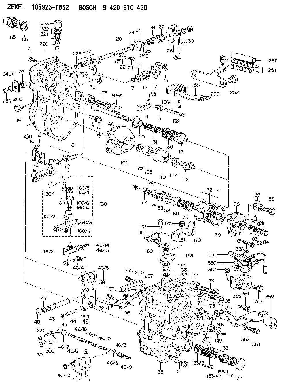
Information governor
BOSCH
9 420 610 450
9420610450
ZEXEL
105923-1852
1059231852
MITSUBISHI
ME741625
me741625

Rating:
Scheme ###:
| 1. | [1] | 159360-0820 | GOVERNOR HOUSING |
| 4. | [1] | 159362-5520 | PLATE |
| 5. | [8] | 139006-6100 | BLEEDER SCREW |
| 5. | [8] | 139006-6100 | BLEEDER SCREW |
| 7. | [1] | 139709-0100 | O-RING |
| 8. | [1] | 159364-3720 | LEVER SHAFT |
| 9. | [1] | 159362-5620 | CONTROL LEVER |
| 10. | [1] | 016010-0740 | LOCKING WASHER |
| 11/1. | [0] | 029311-0220 | SHIM D18&10.3T0.2 |
| 11/1. | [0] | 029311-0230 | SHIM D18&10.3T0.5 |
| 11/1. | [0] | 029311-0430 | SHIM D18&10.3T0.30 |
| 11/1. | [0] | 029311-0440 | SHIM D18&10.3T0.40 |
| 11/1. | [0] | 029311-0450 | SHIM D18&10.3T0.25 |
| 11/1. | [0] | 029311-0460 | SHIM D18&10.3T0.35 |
| 11/1. | [0] | 139410-3300 | SHIM D18&10.3T0.6 |
| 11/1. | [0] | 139410-3400 | SHIM D18&10.3T0.8 |
| 11/1. | [0] | 139410-3500 | SHIM D18&10.3T0.9 |
| 12. | [1] | 159368-8000 | COILED SPRING |
| 13. | [1] | 159362-4100 | CONTROL LEVER |
| 15. | [1] | 013020-8040 | UNION NUT M8P1.25H7 |
| 16. | [1] | 159364-5100 | CAPSULE |
| 17. | [1] | 159362-1821 | CONTROL LEVER |
| 18. | [1] | 159368-6800 | COILED SPRING |
| 20. | [1] | 159364-3800 | LEVER SHAFT |
| 21. | [2] | 020104-1240 | BLEEDER SCREW |
| 22. | [1] | 159362-0600 | CONTROL LEVER |
| 23. | [2] | 139608-0600 | PACKING RING |
| 23. | [2] | 139608-0600 | PACKING RING |
| 24. | [1] | 159362-0700 | PLAIN WASHER |
| 24B/1. | [0] | 139408-1000 | SHIM D16&8T0.5 |
| 24B/1. | [0] | 139408-1300 | SHIM D16&8T0.2 |
| 24C. | [1] | 159362-0700 | PLAIN WASHER |
| 24D. | [1] | 139308-2100 | PLAIN WASHER |
| 25. | [1] | 159238-4200 | LOCKING WASHER |
| 25B. | [1] | 159238-4200 | LOCKING WASHER |
| 26. | [1] | 159390-3421 | CONTROL LEVER |
| 27. | [1] | 159368-6100 | COILED SPRING |
| 28. | [1] | 159364-6000 | BUSHING |
| 29. | [1] | 014110-8440 | LOCKING WASHER |
| 30. | [1] | 013020-8040 | UNION NUT M8P1.25H7 |
| 31. | [1] | 155644-1301 | BLEEDER SCREW |
| 32. | [1] | 013030-6040 | UNION NUT M6P1H3.6 |
| 35. | [1] | 159361-0320 | GOVERNOR COVER |
| 43. | [1] | 159364-0700 | LEVER SHAFT |
| 44. | [1] | 159364-0800 | BEARING PIN |
| 45. | [2] | 016010-0640 | LOCKING WASHER |
| 46. | [1] | 159363-5720 | TENSIONING LEVER |
| 46/1. | [1] | 159363-5620 | TENSIONING LEVER |
| 46/2. | [1] | 159362-8221 | GUIDE LEVER |
| 46/3. | [1] | 159364-4201 | BEARING PIN |
| 46/4. | [1] | 159368-6201 | COILED SPRING |
| 46/5. | [1] | 016010-0540 | LOCKING WASHER |
| 46/6. | [1] | 016010-0440 | LOCKING WASHER |
| 46/7. | [1] | 159364-4121 | RACK |
| 46/8. | [1] | 159364-4300 | UNION NUT |
| 46/9. | [1] | 159364-4400 | FLAT-HEAD SCREW |
| 46/10. | [1] | 159368-6900 | COILED SPRING |
| 46/11. | [1] | 159368-7000 | COILED SPRING |
| 46/13. | [1] | 016010-0540 | LOCKING WASHER |
| 46/14. | [1] | 159364-1900 | FLAT-HEAD SCREW |
| 46/15. | [1] | 159364-1800 | UNION NUT |
| 46/16. | [1] | 159368-9500 | COILED SPRING |
| 47. | [2] | 016110-1020 | LOCKING WASHER |
| 48. | [2] | 159237-0200 | CAPSULE |
| 51. | [9] | 020106-3840 | BLEEDER SCREW |
| 56. | [1] | 159362-3720 | LEVER GROUP |
| 57. | [2] | 020105-1040 | BLEEDER SCREW M5P0.8L10 |
| 58. | [1] | 146711-0000 | PLATE |
| 59. | [1] | 154413-3600 | BUSHING |
| 60. | [1] | 146716-0000 | UNION NUT |
| 65. | [1] | 155404-3400 | CAP |
| 66. | [1] | 026524-3040 | GASKET |
| 70. | [1] | 154402-4800 | COILED SPRING |
| 71. | [2] | 154413-2600 | GASKET |
| 72. | [1] | 154415-1020 | DIAPHRAGM |
| 75. | [1] | 154415-1100 | SLOTTED WASHER |
| 76. | [1] | 014110-6440 | LOCKING WASHER |
| 77. | [1] | 013030-6010 | UNION NUT |
| 79. | [1] | 154413-4000 | FLAT-HEAD SCREW |
| 80. | [1] | 154404-5000 | COVER |
| 82. | [2] | 026506-1040 | GASKET D9.9&6.2T1 |
| 83. | [1] | 013030-6040 | UNION NUT M6P1H3.6 |
| 84. | [1] | 154035-1600 | CAP NUT |
| 88. | [1] | 029731-0180 | EYE BOLT |
| 89. | [2] | 026510-1340 | GASKET D13.4&10.2T1 |
| 91. | [1] | 020106-2040 | BLEEDER SCREW M6P1L20 |
| 92. | [2] | 139006-7000 | BLEEDER SCREW |
| 92A. | [2] | 014110-6440 | LOCKING WASHER |
| 95. | [1] | 029111-2090 | CAPSULE |
| 96. | [1] | 029331-2130 | GASKET |
| 97. | [1] | 159364-2000 | CAPSULE |
| 100. | [1] | 154100-9220 | FLYWEIGHT ASSEMBLY |
| 101. | [1] | 025803-1310 | WOODRUFF KEY |
| 102. | [1] | 029321-2020 | LOCKING WASHER |
| 103. | [1] | 029231-2030 | UNION NUT |
| 110. | [1] | 154123-2320 | SLIDING PIECE |
| 111/1. | [0] | 029311-0010 | SHIM D14&10.1T0.2 |
| 111/1. | [0] | 029311-0180 | SHIM D14&10.1T0.3 |
| 111/1. | [0] | 029311-0190 | SHIM D14&10.1T0.40 |
| 111/1. | [0] | 029311-0210 | SHIM D14&10.1T1 |
| 111/1. | [0] | 139410-0000 | SHIM D14.0&10.1T0.5 |
| 111/1. | [0] | 139410-0100 | SHIM D14.0&10.1T1.5 |
| 111/1. | [0] | 139410-3000 | SHIM D14&10.1T2.0 |
| 111/1. | [0] | 139410-3100 | SHIM D14&10.1T3.0 |
| 111/1. | [0] | 139410-3200 | SHIM D14&10.1T4.0 |
| 112. | [1] | 159364-5200 | TERMINAL STUD |
| 130. | [1] | 159367-0000 | GOVERNOR SPRING |
| 131. | [1] | 159367-6400 | GOVERNOR SPRING |
| 132. | [1] | 159368-6500 | COILED SPRING |
| 133. | [1] | 159368-2220 | SPRING PACK |
| 133/1. | [1] | 159364-2200 | GUIDE SLEEVE |
| 133/2. | [1] | 159368-0100 | COILED SPRING |
| 133/3. | [1] | 159368-0500 | COILED SPRING |
| 133/4/1. | [0] | 029311-0010 | SHIM D14&10.1T0.2 |
| 133/4/1. | [0] | 029311-0180 | SHIM D14&10.1T0.3 |
| 133/4/1. | [0] | 029311-0190 | SHIM D14&10.1T0.40 |
| 133/4/1. | [0] | 029311-0210 | SHIM D14&10.1T1 |
| 133/4/1. | [0] | 139410-0000 | SHIM D14.0&10.1T0.5 |
| 133/4/1. | [0] | 139410-0100 | SHIM D14.0&10.1T1.5 |
| 133/4/1. | [0] | 139410-3000 | SHIM D14&10.1T2.0 |
| 133/4/1. | [0] | 139410-3100 | SHIM D14&10.1T3.0 |
| 133/4/1. | [0] | 139410-3200 | SHIM D14&10.1T4.0 |
| 135. | [1] | 159364-2300 | FLAT-HEAD SCREW |
| 137. | [1] | 159364-2000 | CAPSULE |
| 140. | [1] | 159364-2500 | LEVER SHAFT |
| 145. | [1] | 159233-5700 | UNION NUT |
| 149. | [1] | 159237-5400 | CAPSULE |
| 150. | [1] | 159364-2600 | SLOTTED WASHER |
| 151. | [1] | 159364-2700 | SLOTTED WASHER |
| 155. | [1] | 159363-2721 | STRAP |
| 156. | [1] | 010235-1020 | HEX-SOCKET-HEAD CAP SCREW |
| 160. | [1] | 159362-2020 | LEVER GROUP |
| 160/1. | [1] | 159364-3220 | LEVER SHAFT |
| 160/2. | [1] | 159362-1020 | CONTROL LEVER |
| 160/3. | [1] | 159362-2000 | CONTROL LEVER |
| 160/4. | [2] | 159362-1300 | SHIM |
| 160/4. | [2] | 159362-1300 | SHIM |
| 160/5. | [2] | 016010-0840 | LOCKING WASHER |
| 160/5. | [2] | 016010-0840 | LOCKING WASHER |
| 160/6. | [1] | 159368-6600 | COILED SPRING |
| 162. | [1] | 139411-0600 | SHIM |
| 163. | [1] | 159238-3000 | LOCKING WASHER |
| 164. | [1] | 139610-0800 | PACKING RING |
| 168. | [1] | 159380-0300 | CONTROL LEVER |
| 169. | [1] | 013020-8040 | UNION NUT M8P1.25H7 |
| 170. | [1] | 159380-5420 | CONTROL LEVER |
| 172. | [4] | 020106-1240 | BLEEDER SCREW M6P1.0L12 |
| 172. | [4] | 020106-1240 | BLEEDER SCREW M6P1.0L12 |
| 173. | [1] | 154013-1700 | BLEEDER SCREW |
| 173B. | [1] | 154013-1800 | BLEEDER SCREW |
| 173C. | [1] | 154013-1900 | BLEEDER SCREW |
| 174. | [1] | 154013-2000 | BLEEDER SCREW |
| 175. | [1] | 154013-3300 | BLEEDER SCREW |
| 176. | [1] | 154011-4000 | UNION NUT |
| 177. | [1] | 154011-4100 | UNION NUT |
| 178. | [1] | 139210-0400 | UNION NUT |
| 181. | [1] | 159381-5220 | CONTROL LEVER |
| 220. | [1] | 159368-8420 | HEADLESS SCREW |
| 221. | [1] | 154011-4300 | UNION NUT |
| 222. | [2] | 026512-1540 | GASKET D15.4&12.2T1.50 |
| 223. | [1] | 154159-2100 | CAP NUT |
| 225. | [2] | 029310-8050 | SHIM D13.5&8T0.5 |
| 226. | [1] | 159368-9101 | COILED SPRING |
| 227. | [1] | 159362-6720 | CONTROL LEVER |
| 236. | [1] | 154390-4100 | GASKET |
| 237. | [1] | 154390-2500 | GASKET |
| 250. | [1] | 159398-4520 | BRACKET |
| 251. | [2] | 154338-5100 | COILED SPRING |
| 252. | [2] | 010010-1240 | BLEEDER SCREW M10P1.5L12 4T |
| 257. | [2] | 154156-2500 | TUBE |
| 270. | [1] | 159362-4620 | GUIDE PLATE |
| 271. | [2] | 020106-1640 | BLEEDER SCREW M6P1.0L14 |
| 300. | [1] | 159373-4400 | CAM PLATE |
| 301. | [1] | 016010-0840 | LOCKING WASHER |
| 303. | [1] | 016010-0540 | LOCKING WASHER |
| 311. | [2] | 159237-5400 | CAPSULE |
| 321/1. | [1] | 159274-5100 | STOP PIN L72.5 |
| 321/1. | [1] | 159274-5200 | STOP PIN L73 |
| 321/1. | [1] | 159274-5300 | STOP PIN L73.5 |
| 321/1. | [1] | 159274-5400 | STOP PIN L74 |
| 321/1. | [1] | 159274-5500 | STOP PIN L74.5 |
| 321/1. | [1] | 159274-5600 | STOP PIN L75 |
| 321/1. | [1] | 159274-5700 | STOP PIN L75.5 |
| 321/1. | [1] | 159274-5800 | STOP PIN L76 |
| 321/1. | [1] | 159274-5900 | STOP PIN L76.5 |
| 321/1. | [1] | 159274-6000 | STOP PIN L77 |
| 321/1. | [1] | 159274-6100 | STOP PIN L77.5 |
| 321/1. | [1] | 159274-6200 | STOP PIN L78 |
| 321/1. | [1] | 159274-6300 | STOP PIN L78.5 |
| 321/1. | [1] | 159274-6400 | STOP PIN L79 |
| 321/1. | [1] | 159274-6500 | STOP PIN L79.5 |
| 321/1. | [1] | 159274-6600 | STOP PIN L80 |
| 321/1. | [1] | 159274-6700 | STOP PIN L80.5 |
| 321/1. | [1] | 159274-6800 | STOP PIN L81 |
| 321/1. | [1] | 159274-6900 | STOP PIN L81.5 |
| 321/1. | [1] | 159274-7000 | STOP PIN L82 |
| 321/1. | [1] | 159274-7100 | STOP PIN L82.5 |
| 321/1. | [1] | 159274-7200 | STOP PIN L83 |
| 321/1. | [1] | 159274-7300 | STOP PIN L83.5 |
| 321/1. | [1] | 159274-7400 | STOP PIN L84 |
| 321/1. | [1] | 159274-7500 | STOP PIN L84.5 |
| 321/1. | [1] | 159274-7600 | STOP PIN L85 |
| 321/1. | [1] | 159274-7700 | STOP PIN L85.5 |
| 321/1. | [1] | 159274-7800 | STOP PIN L86 |
| 321/1. | [1] | 159274-7900 | STOP PIN L86.5 |
| 321/1. | [1] | 159274-8000 | STOP PIN L87 |
| 321/1. | [1] | 159274-8100 | STOP PIN L87.5 |
| 321/1. | [1] | 159274-8200 | STOP PIN L88 |
| 321/1. | [1] | 159274-8300 | STOP PIN L88.5 |
| 321/1. | [1] | 159274-8400 | STOP PIN L89 |
| 321/1. | [1] | 159274-8500 | STOP PIN L89.5 |
| 321/1. | [1] | 159274-8600 | STOP PIN L90 |
| 355. | [1] | 159395-5600 | BRACKET |
| 356. | [1] | 010110-1640 | BLEEDER SCREW M101.25L16 |
| 357. | [1] | 020106-1240 | BLEEDER SCREW M6P1.0L12 |
| 360. | [1] | 159396-9321 | BRACKET |
| 361. | [3] | 020106-1640 | BLEEDER SCREW M6P1.0L14 |
| 361. | [3] | 020106-1640 | BLEEDER SCREW M6P1.0L14 |
| 362. | [2] | 154604-4500 | PLAIN WASHER |
| 550. | [1] | 153146-3220 | MICROSWITCH |
| 551. | [1] | 154614-8020 | CLAMPING BAND |
Include in #1:
106673-7282
as GOVERNOR
Cross reference number
Zexel num
Bosch num
Firm num
Name
105923-1852
ME741625 MITSUBISHI
GOVERNOR
K 14JF MECHANICAL GOVERNOR GOV RLD-J(P) GOV
K 14JF MECHANICAL GOVERNOR GOV RLD-J(P) GOV
Information:
P-226: Fuel Pressure Sensor Test
The 3176 System monitors fuel pressure with a sensor located at the top of the fuel filter housing. The Fuel Pressure Sensor is supplied with 5.0 volts DC through the ECM Connector (J4/P4, Pin 10). The sensor return line goes through the ECM Connector (J4/P4, Pin 35). Both lines are also common with the Coolant Temperature Sensor. The Fuel Pressure Signal goes to the ECM Connector (J4/P4, Pin 39).Fuel pressure is regulated to a maximum of approximately 550 kPa (80 psi). Step 1. Inspect Connectors And WiringInspect the Fuel Pressure Sensor Connector (J16/P16) and the ECM Connector (J4/P4) and wiring between being sure to: * Check Connector lock rings.* Perform 10 pound pull test on each pin or wire.* Inspect wiring for damage or abrasion.* Inspect connectors for damage or corrosion. Refer to P-201: Inspecting Electrical Connectors for details. Repair any damage, then continue with the next step. Step 2. Check Actual Pressure With GaugeA. Install the 8T0846 Pressure Gauge (0 to 145 psi)(part of 1U5470 Pressure Group) on a "T" fitting with the Fuel Pressure Sensor.B. Start the engine and monitor the fuel pressure at low idle.C. Operate the engine at high idle and check the fuel pressure. Fuel pressure at low idle should be greater than 300 kPa (43.5 psi), and at high idle should be 550 85 kPa (80 12 psi) and remain steady. OK: Fuel pressure is within normal limits. Continue to next step. NOT OK: Fuel pressure is outside normal limits, is erratic or leakage is present. The problem is NOT in the 3176 Electronic Control System. Refer to 3176 Vehicular Diesel Engine, Form No. SENR4964, for Systems Operation, Testing & Adjusting, for help in identifying and repairing the cause of the problem. STOP Step 3. Compare Gauge Reading With ECAP/DDTA. With key OFF, install ECAP/DDT on the 3176 System.B. Start the engine and run at low idle. Compare the gauge reading with the display on the ECAP or DDT and record.C. Operate the engine at high idle. Compare the gauge reading with the display on the ECAP or DDT and record. The ECAP/DDT display should be steady and within 40 kPa (6 psi) of the gauge readings. OK: The Fuel Pressure Sensor is operating correctly. STOP. NOT OK: The ECM is not reading fuel pressure correctly. Continue to next step. Step 4. Check Supply Voltage To SensorA. With key OFF, install the 3-Pin Breakout "T" on the Fuel Pressure Wiring Connector (J16) ONLY. Do not connect to the Fuel Pressure Sensor Connector (P16) at this time.B. Turn key ON (engine off).C. Use the multimeter to measure the voltage between + V, Pin A (J16) and Return, Pin B on the 3-Pin Breakout "T". The voltage should be 5.0 0.5 volts DC. OK: The Fuel Pressure Sensor is receiving the correct voltage. Proceed to Step 7. NOT OK: Supply voltage is not reaching the sensor. Continue to next step. Step 5. Check Supply
The 3176 System monitors fuel pressure with a sensor located at the top of the fuel filter housing. The Fuel Pressure Sensor is supplied with 5.0 volts DC through the ECM Connector (J4/P4, Pin 10). The sensor return line goes through the ECM Connector (J4/P4, Pin 35). Both lines are also common with the Coolant Temperature Sensor. The Fuel Pressure Signal goes to the ECM Connector (J4/P4, Pin 39).Fuel pressure is regulated to a maximum of approximately 550 kPa (80 psi). Step 1. Inspect Connectors And WiringInspect the Fuel Pressure Sensor Connector (J16/P16) and the ECM Connector (J4/P4) and wiring between being sure to: * Check Connector lock rings.* Perform 10 pound pull test on each pin or wire.* Inspect wiring for damage or abrasion.* Inspect connectors for damage or corrosion. Refer to P-201: Inspecting Electrical Connectors for details. Repair any damage, then continue with the next step. Step 2. Check Actual Pressure With GaugeA. Install the 8T0846 Pressure Gauge (0 to 145 psi)(part of 1U5470 Pressure Group) on a "T" fitting with the Fuel Pressure Sensor.B. Start the engine and monitor the fuel pressure at low idle.C. Operate the engine at high idle and check the fuel pressure. Fuel pressure at low idle should be greater than 300 kPa (43.5 psi), and at high idle should be 550 85 kPa (80 12 psi) and remain steady. OK: Fuel pressure is within normal limits. Continue to next step. NOT OK: Fuel pressure is outside normal limits, is erratic or leakage is present. The problem is NOT in the 3176 Electronic Control System. Refer to 3176 Vehicular Diesel Engine, Form No. SENR4964, for Systems Operation, Testing & Adjusting, for help in identifying and repairing the cause of the problem. STOP Step 3. Compare Gauge Reading With ECAP/DDTA. With key OFF, install ECAP/DDT on the 3176 System.B. Start the engine and run at low idle. Compare the gauge reading with the display on the ECAP or DDT and record.C. Operate the engine at high idle. Compare the gauge reading with the display on the ECAP or DDT and record. The ECAP/DDT display should be steady and within 40 kPa (6 psi) of the gauge readings. OK: The Fuel Pressure Sensor is operating correctly. STOP. NOT OK: The ECM is not reading fuel pressure correctly. Continue to next step. Step 4. Check Supply Voltage To SensorA. With key OFF, install the 3-Pin Breakout "T" on the Fuel Pressure Wiring Connector (J16) ONLY. Do not connect to the Fuel Pressure Sensor Connector (P16) at this time.B. Turn key ON (engine off).C. Use the multimeter to measure the voltage between + V, Pin A (J16) and Return, Pin B on the 3-Pin Breakout "T". The voltage should be 5.0 0.5 volts DC. OK: The Fuel Pressure Sensor is receiving the correct voltage. Proceed to Step 7. NOT OK: Supply voltage is not reaching the sensor. Continue to next step. Step 5. Check Supply