Information governor
BOSCH
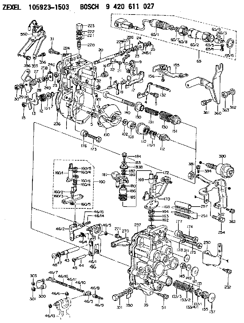
9 420 611 027
9420611027
ZEXEL
105923-1503
1059231503
MITSUBISHI
ME741587
me741587
Rating:
Scheme ###:
| 1. | [1] | 159360-0420 | GOVERNOR HOUSING |
| 4. | [1] | 159362-5520 | PLATE |
| 5. | [8] | 139006-6100 | BLEEDER SCREW |
| 5. | [8] | 139006-6100 | BLEEDER SCREW |
| 7. | [1] | 139709-0100 | O-RING |
| 8. | [1] | 159364-0120 | LEVER SHAFT |
| 9. | [1] | 159362-5620 | CONTROL LEVER |
| 10. | [1] | 016010-0740 | LOCKING WASHER |
| 11/1. | [0] | 029311-0220 | SHIM D18&10.3T0.2 |
| 11/1. | [0] | 029311-0230 | SHIM D18&10.3T0.5 |
| 11/1. | [0] | 029311-0430 | SHIM D18&10.3T0.30 |
| 11/1. | [0] | 029311-0440 | SHIM D18&10.3T0.40 |
| 11/1. | [0] | 029311-0450 | SHIM D18&10.3T0.25 |
| 11/1. | [0] | 029311-0460 | SHIM D18&10.3T0.35 |
| 11/1. | [0] | 139410-3300 | SHIM D18&10.3T0.6 |
| 11/1. | [0] | 139410-3400 | SHIM D18&10.3T0.8 |
| 11/1. | [0] | 139410-3500 | SHIM D18&10.3T0.9 |
| 12. | [1] | 159368-7800 | COILED SPRING |
| 13. | [1] | 159362-1500 | CONTROL LEVER |
| 15. | [1] | 013020-8040 | UNION NUT M8P1.25H7 |
| 16. | [1] | 159364-5000 | CAPSULE |
| 17. | [1] | 159362-0520 | CONTROL LEVER |
| 18. | [1] | 159215-0600 | COILED SPRING |
| 20. | [1] | 159364-3800 | LEVER SHAFT |
| 21. | [2] | 020104-1240 | BLEEDER SCREW |
| 22. | [1] | 159362-0600 | CONTROL LEVER |
| 23. | [2] | 139608-0600 | PACKING RING |
| 23. | [2] | 139608-0600 | PACKING RING |
| 24. | [1] | 159362-0700 | PLAIN WASHER |
| 24B/1. | [0] | 139408-1000 | SHIM D16&8T0.5 |
| 24B/1. | [0] | 139408-1300 | SHIM D16&8T0.2 |
| 24C. | [1] | 159362-0700 | PLAIN WASHER |
| 24D. | [1] | 139308-2100 | PLAIN WASHER |
| 25. | [1] | 159238-4200 | LOCKING WASHER |
| 25B. | [1] | 159238-4200 | LOCKING WASHER |
| 26. | [1] | 159390-2100 | CONTROL LEVER |
| 27. | [1] | 159368-7300 | COILED SPRING |
| 28. | [1] | 159364-6000 | BUSHING |
| 29. | [1] | 014110-8440 | LOCKING WASHER |
| 30. | [1] | 013020-8040 | UNION NUT M8P1.25H7 |
| 31. | [1] | 155644-1301 | BLEEDER SCREW |
| 32. | [1] | 013030-6040 | UNION NUT M6P1H3.6 |
| 35. | [1] | 159361-0520 | GOVERNOR COVER |
| 43. | [1] | 159364-0700 | LEVER SHAFT |
| 44. | [1] | 159364-0800 | BEARING PIN |
| 45. | [2] | 016010-0640 | LOCKING WASHER |
| 46. | [1] | 159362-8420 | TENSIONING LEVER |
| 46/1. | [1] | 159362-8320 | TENSIONING LEVER |
| 46/2. | [1] | 159362-8221 | GUIDE LEVER |
| 46/3. | [1] | 159364-4201 | BEARING PIN |
| 46/4. | [1] | 159368-6201 | COILED SPRING |
| 46/5. | [1] | 016010-0540 | LOCKING WASHER |
| 46/6. | [1] | 016010-0440 | LOCKING WASHER |
| 46/7. | [1] | 159364-4121 | RACK |
| 46/8. | [1] | 159364-4300 | UNION NUT |
| 46/9. | [1] | 159364-4400 | FLAT-HEAD SCREW |
| 46/10. | [1] | 159368-6900 | COILED SPRING |
| 46/11. | [1] | 159368-7000 | COILED SPRING |
| 46/13. | [1] | 016010-0540 | LOCKING WASHER |
| 46/14. | [1] | 159364-1900 | FLAT-HEAD SCREW |
| 46/15. | [1] | 159364-1800 | UNION NUT |
| 46/16. | [1] | 159368-9500 | COILED SPRING |
| 47. | [2] | 016110-1020 | LOCKING WASHER |
| 48. | [2] | 159237-0200 | CAPSULE |
| 51. | [9] | 020106-3840 | BLEEDER SCREW |
| 65. | [1] | 154611-9220 | RACK SENSOR ASSY |
| 65/1. | [1] | 479775-5320 | RACK SENSOR |
| 65/2. | [1] | 154614-4800 | JOINT CONNECTION |
| 65/3. | [1] | 154614-3200 | BLOCK |
| 65/4. | [1] | 010234-1040 | HEX-SOCKET-HEAD CAP SCREW |
| 65/5. | [1] | 014110-4440 | LOCKING WASHER |
| 65/6. | [1] | 026524-3040 | GASKET |
| 65/7A. | [0] | 029310-6220 | SHIM D11.5&6.5T0.10 |
| 65/7B. | [0] | 029310-6230 | SHIM D11.5&6.5T0.20 |
| 65/7C. | [0] | 029310-6240 | SHIM D11.5&6.5T0.25 |
| 65/7D. | [0] | 029310-6260 | SHIM D11.5&6.4T1.00 |
| 65/7E. | [0] | 029310-6270 | SHIM D11.5&6.4T1.20 |
| 65/7F. | [0] | 029310-6280 | SHIM D11.5&6.4T1.50 |
| 65/8. | [1] | 154614-1900 | UNION NUT |
| 65/9. | [1] | 154614-3300 | BEARING PIN |
| 97. | [1] | 159364-2000 | CAPSULE |
| 100. | [1] | 154100-9220 | FLYWEIGHT ASSEMBLY |
| 101. | [1] | 025803-1310 | WOODRUFF KEY |
| 102. | [1] | 029321-2020 | LOCKING WASHER |
| 103. | [1] | 029231-2030 | UNION NUT |
| 110. | [1] | 154123-2320 | SLIDING PIECE |
| 111/1. | [0] | 029311-0010 | SHIM D14&10.1T0.2 |
| 111/1. | [0] | 029311-0180 | SHIM D14&10.1T0.3 |
| 111/1. | [0] | 029311-0190 | SHIM D14&10.1T0.40 |
| 111/1. | [0] | 029311-0210 | SHIM D14&10.1T1 |
| 111/1. | [0] | 139410-0000 | SHIM D14.0&10.1T0.5 |
| 111/1. | [0] | 139410-0100 | SHIM D14.0&10.1T1.5 |
| 111/1. | [0] | 139410-3000 | SHIM D14&10.1T2.0 |
| 111/1. | [0] | 139410-3100 | SHIM D14&10.1T3.0 |
| 111/1. | [0] | 139410-3200 | SHIM D14&10.1T4.0 |
| 112. | [1] | 159364-5200 | TERMINAL STUD |
| 130. | [1] | 159367-1400 | GOVERNOR SPRING |
| 131. | [1] | 159367-6300 | GOVERNOR SPRING |
| 132. | [1] | 159368-6500 | COILED SPRING |
| 133. | [1] | 159368-2420 | SPRING PACK |
| 133/1. | [1] | 159364-2200 | GUIDE SLEEVE |
| 133/2. | [1] | 159368-0100 | COILED SPRING |
| 133/3. | [1] | 159368-0600 | COILED SPRING |
| 133/4/1. | [0] | 029311-0010 | SHIM D14&10.1T0.2 |
| 133/4/1. | [0] | 029311-0180 | SHIM D14&10.1T0.3 |
| 133/4/1. | [0] | 029311-0190 | SHIM D14&10.1T0.40 |
| 133/4/1. | [0] | 029311-0210 | SHIM D14&10.1T1 |
| 133/4/1. | [0] | 139410-0000 | SHIM D14.0&10.1T0.5 |
| 133/4/1. | [0] | 139410-0100 | SHIM D14.0&10.1T1.5 |
| 133/4/1. | [0] | 139410-3000 | SHIM D14&10.1T2.0 |
| 133/4/1. | [0] | 139410-3100 | SHIM D14&10.1T3.0 |
| 133/4/1. | [0] | 139410-3200 | SHIM D14&10.1T4.0 |
| 135. | [1] | 159364-2300 | FLAT-HEAD SCREW |
| 137. | [1] | 159364-2000 | CAPSULE |
| 140. | [1] | 159364-2500 | LEVER SHAFT |
| 145. | [1] | 159233-5700 | UNION NUT |
| 149. | [1] | 159237-5400 | CAPSULE |
| 150. | [1] | 159364-2600 | SLOTTED WASHER |
| 151. | [1] | 159364-2700 | SLOTTED WASHER |
| 155. | [1] | 159363-2620 | STRAP |
| 156. | [1] | 010235-1020 | HEX-SOCKET-HEAD CAP SCREW |
| 160. | [1] | 159362-7720 | LEVER GROUP |
| 160/1. | [1] | 159364-9520 | LEVER SHAFT |
| 160/2. | [1] | 159362-1020 | CONTROL LEVER |
| 160/3. | [1] | 159362-2000 | CONTROL LEVER |
| 160/4. | [2] | 159362-1300 | SHIM |
| 160/4. | [2] | 159362-1300 | SHIM |
| 160/5. | [2] | 016010-0840 | LOCKING WASHER |
| 160/5. | [2] | 016010-0840 | LOCKING WASHER |
| 160/6. | [1] | 159368-6600 | COILED SPRING |
| 162. | [1] | 139411-0600 | SHIM |
| 163. | [1] | 159238-3000 | LOCKING WASHER |
| 164. | [1] | 139610-0800 | PACKING RING |
| 168. | [1] | 159381-5800 | CONTROL LEVER |
| 169. | [1] | 159233-7301 | UNION NUT |
| 170. | [1] | 159381-8420 | CONTROL LEVER |
| 172. | [2] | 020106-1240 | BLEEDER SCREW M6P1.0L12 |
| 173. | [1] | 154013-1700 | BLEEDER SCREW |
| 173B. | [1] | 154013-1800 | BLEEDER SCREW |
| 173C. | [1] | 154013-1900 | BLEEDER SCREW |
| 174. | [1] | 154013-2000 | BLEEDER SCREW |
| 175. | [1] | 154013-3300 | BLEEDER SCREW |
| 176. | [1] | 154011-4000 | UNION NUT |
| 177. | [1] | 154011-4100 | UNION NUT |
| 178. | [1] | 139210-0400 | UNION NUT |
| 180. | [2] | 139310-0500 | PLAIN WASHER |
| 180. | [2] | 139310-0500 | PLAIN WASHER |
| 181. | [1] | 159381-8920 | CONTROL LEVER |
| 182. | [0] | 029311-0010 | SHIM D14&10.1T0.2 |
| 183. | [1] | 014010-6140 | PLAIN WASHER D13&6.5T1 |
| 183B. | [1] | 159235-7100 | CAP |
| 184. | [1] | 020006-1270 | BLEEDER SCREW M6P1L12 7T |
| 185. | [1] | 159369-1100 | COILED SPRING |
| 186. | [1] | 159230-7100 | BUSHING |
| 220. | [1] | 159368-8420 | HEADLESS SCREW |
| 221. | [1] | 154011-4300 | UNION NUT |
| 222. | [2] | 026512-1540 | GASKET D15.4&12.2T1.50 |
| 223. | [1] | 154159-2100 | CAP NUT |
| 225. | [2] | 029310-8050 | SHIM D13.5&8T0.5 |
| 226. | [1] | 159368-9101 | COILED SPRING |
| 227. | [1] | 159362-6720 | CONTROL LEVER |
| 236. | [1] | 154390-4100 | GASKET |
| 237. | [1] | 154390-2500 | GASKET |
| 250. | [1] | 159397-7420 | BRACKET |
| 251. | [2] | 154339-2200 | COILED SPRING |
| 252. | [2] | 020106-1240 | BLEEDER SCREW M6P1.0L12 |
| 254. | [1] | 020010-2540 | BLEEDER SCREW M10P1.25L25 |
| 257. | [2] | 154156-3100 | TUBE |
| 270. | [1] | 159362-7020 | GUIDE PLATE |
| 271. | [2] | 020106-1640 | BLEEDER SCREW M6P1.0L14 |
| 300. | [1] | 159372-7300 | CAM PLATE |
| 301. | [1] | 016010-0840 | LOCKING WASHER |
| 303. | [1] | 016010-0540 | LOCKING WASHER |
| 311. | [2] | 159237-5400 | CAPSULE |
| 350. | [2] | 139512-0000 | GASKET D17.2&12.2T1.0 |
| 351. | [1] | 139812-0100 | EYE BOLT |
| 355. | [1] | 159397-8020 | BRACKET |
| 356. | [3] | 020106-1240 | BLEEDER SCREW M6P1.0L12 |
| 356. | [3] | 020106-1240 | BLEEDER SCREW M6P1.0L12 |
| 360. | [1] | 159397-5500 | BRACKET |
| 361. | [2] | 020018-1640 | BLEEDER SCREW M8P1.25L16 4T |
| 362. | [2] | 159276-1300 | BUSHING |
| 363. | [2] | 156914-2300 | BLEEDER SCREW |
| 380. | [1] | 159397-7800 | DAMPER |
| 381. | [1] | 029201-4140 | UNION NUT M14P1.5H5 |
| 382. | [1] | 159397-7920 | BRACKET |
| 383. | [1] | 020106-1240 | BLEEDER SCREW M6P1.0L12 |
| 384. | [1] | 020106-1040 | BLEEDER SCREW M6P1L12 |
| 550. | [1] | 153146-6020 | MICROSWITCH |
Include in #1:
106873-7292
as GOVERNOR
Cross reference number
Zexel num
Bosch num
Firm num
Name
Information:
Installation of Nozzles, Ether Supply Tubes and Connectors
1. If the machine does not already have an ether aid starting system, remove the plugs from turbocharger outlet adapters on the engine. 2. Install a 3B6768 Bushing with a 7X1078 Nozzle Assembly (2) where each plug was removed. If machine was equipped with an ether aid starting system. Discard old nozzles and install new nozzles.3. When installing each nozzle assembly (2), the indicator mark at location (J) must be at the top as shown. Tighten the nozzle to a torque of 2.8 N m (25 lb in).
Top View
Side View DO NOT overtighten tube assembly fittings. Over tightening can cause damage to tubing.4. Install 8X0912 Tube (9) in the front nozzle and 8W8174 Tube (7) in the rear nozzle as shown. Connect tubes (7) and (9) to 8C9006 Tee (8) using two 5P6314 Sleeves and 5P6313 Nuts.5. Put 8W8172 Tube (5) in position along the cylinder block and connect it to 8C9006 Tee (8) as shown using 5P6314 Sleeve and 5P6313 Nut.6. Connect one end of 8W8171 Tube (10) to elbow (11) on the bottom of the shuttle valve using a 5P6313 Nut and 5P6314 Sleeve. Fasten the tube to the frame cross tube using 6V2686 Clip (6) as shown.7. Connect one end of 7N0140 Tube Assembly (4) to the end of 8W8171 Tube (10) and connect the other end to the free end of 8W8172 Tube (5).8. Fasten the ether tubing assemblies, using three 6V2686 Clips (3) with existing bolts, on engine block and right regulator housing as shown.Installation of Ether Cylinders
1. Turn the disconnect switch to the ON position and put the start switch key in the OFF position. Make sure the two lamps on the console and the two yellow LEDs on the ECU are flashing.If they are flashing, it indicates that the control is functioning and recognizes that no ether cylinders are installed.2. Inspect the two digit, seven segment LED display on the ECU. It must read "OO". This in an indication that there are no faults.If the display does not read "OO", refer to the Service Manual for a troubleshooting procedure of the system. 3. Remove protective caps (1) and (3) from 9X7137 Ether Solenoid Valves (2) and (4). Install a new 9X7138 Filter Assembly in each solenoid valve inlet.4. Install a 9X0147 Collar on the neck of each new 7X1062 Ether Cylinder.5. Remove the protective plug from the end of the new FULL ether cylinder, then install the new ether cylinder on ether solenoid valve (2). The ether valve assembly at left location (C) is referred to as Ether Assembly No. 1. The ether valve assembly at right location (D) is referred to as Ether Assembly No. 2.Make sure that the dash mounted ETHER OUT warning lamp No. 1 and the ETHER OUT warning LED on the ECU are OFF. Repeat this procedure for installation of