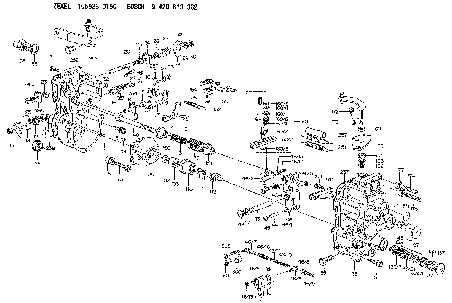
Information governor
BOSCH
9 420 613 362
9420613362
ZEXEL
105923-0150
1059230150
NISSAN-DIESEL
1910197679
1910197679
Rating:
Scheme ###:
| 1. | [1] | 159360-0120 | GOVERNOR HOUSING |
| 4. | [1] | 159362-0000 | PLATE |
| 5. | [8] | 139006-6100 | BLEEDER SCREW |
| 5. | [8] | 139006-6100 | BLEEDER SCREW |
| 7. | [1] | 139709-0100 | O-RING |
| 8. | [1] | 159364-0120 | LEVER SHAFT |
| 9. | [1] | 159362-1900 | CONTROL LEVER |
| 10. | [1] | 016010-0740 | LOCKING WASHER |
| 11/1. | [0] | 029311-0220 | SHIM D18&10.3T0.2 |
| 11/1. | [0] | 029311-0230 | SHIM D18&10.3T0.5 |
| 11/1. | [0] | 029311-0430 | SHIM D18&10.3T0.30 |
| 11/1. | [0] | 029311-0440 | SHIM D18&10.3T0.40 |
| 11/1. | [0] | 029311-0450 | SHIM D18&10.3T0.25 |
| 11/1. | [0] | 029311-0460 | SHIM D18&10.3T0.35 |
| 11/1. | [0] | 139410-3300 | SHIM D18&10.3T0.6 |
| 11/1. | [0] | 139410-3400 | SHIM D18&10.3T0.8 |
| 11/1. | [0] | 139410-3500 | SHIM D18&10.3T0.9 |
| 12. | [1] | 159368-6000 | COILED SPRING |
| 13. | [1] | 159362-1500 | CONTROL LEVER |
| 15. | [1] | 013020-8040 | UNION NUT M8P1.25H7 |
| 16. | [1] | 159237-5621 | ADAPTOR |
| 17. | [1] | 159362-0520 | CONTROL LEVER |
| 18. | [1] | 159215-0600 | COILED SPRING |
| 20. | [1] | 159364-0300 | LEVER SHAFT |
| 21. | [2] | 020104-1240 | BLEEDER SCREW |
| 22. | [1] | 159362-0600 | CONTROL LEVER |
| 23. | [2] | 139608-0600 | PACKING RING |
| 23. | [2] | 139608-0600 | PACKING RING |
| 24. | [1] | 159362-0700 | PLAIN WASHER |
| 24B/1. | [0] | 139408-1000 | SHIM D16&8T0.5 |
| 24B/1. | [0] | 139408-1300 | SHIM D16&8T0.2 |
| 24C. | [1] | 159362-0700 | PLAIN WASHER |
| 25. | [1] | 159238-4200 | LOCKING WASHER |
| 25B. | [1] | 159238-4200 | LOCKING WASHER |
| 26. | [1] | 159390-1020 | CONTROL LEVER |
| 27. | [1] | 159368-6100 | COILED SPRING |
| 28. | [1] | 159364-0400 | BUSHING |
| 29. | [1] | 014110-8440 | LOCKING WASHER |
| 30. | [1] | 013020-8040 | UNION NUT M8P1.25H7 |
| 31. | [1] | 155644-1301 | BLEEDER SCREW |
| 32. | [1] | 013030-6040 | UNION NUT M6P1H3.6 |
| 35. | [1] | 159361-0520 | GOVERNOR COVER |
| 43. | [1] | 159364-0700 | LEVER SHAFT |
| 44. | [1] | 159364-0800 | BEARING PIN |
| 45. | [2] | 016010-0640 | LOCKING WASHER |
| 46. | [1] | 159363-5720 | TENSIONING LEVER |
| 46/1. | [1] | 159363-5620 | TENSIONING LEVER |
| 46/2. | [1] | 159362-8221 | GUIDE LEVER |
| 46/3. | [1] | 159364-4201 | BEARING PIN |
| 46/4. | [1] | 159368-6201 | COILED SPRING |
| 46/5. | [1] | 016010-0540 | LOCKING WASHER |
| 46/6. | [1] | 016010-0440 | LOCKING WASHER |
| 46/7. | [1] | 159364-4121 | RACK |
| 46/8. | [1] | 159364-4300 | UNION NUT |
| 46/9. | [1] | 159364-4400 | FLAT-HEAD SCREW |
| 46/10. | [1] | 159368-6900 | COILED SPRING |
| 46/11. | [1] | 159368-7000 | COILED SPRING |
| 46/13. | [1] | 016010-0540 | LOCKING WASHER |
| 46/14. | [1] | 159364-1900 | FLAT-HEAD SCREW |
| 46/15. | [1] | 159364-1800 | UNION NUT |
| 46/16. | [1] | 159368-9500 | COILED SPRING |
| 47. | [2] | 016110-1020 | LOCKING WASHER |
| 48. | [2] | 159237-0200 | CAPSULE |
| 51. | [9] | 020106-3840 | BLEEDER SCREW |
| 65. | [1] | 155404-3400 | CAP |
| 66. | [1] | 026524-3040 | GASKET |
| 97. | [1] | 159364-2000 | CAPSULE |
| 100. | [1] | 154100-9220 | FLYWEIGHT ASSEMBLY |
| 101. | [1] | 025803-1310 | WOODRUFF KEY |
| 102. | [1] | 029321-2020 | LOCKING WASHER |
| 103. | [1] | 029231-2030 | UNION NUT |
| 110. | [1] | 154123-2320 | SLIDING PIECE |
| 111/1. | [0] | 029311-0010 | SHIM D14&10.1T0.2 |
| 111/1. | [0] | 029311-0180 | SHIM D14&10.1T0.3 |
| 111/1. | [0] | 029311-0190 | SHIM D14&10.1T0.40 |
| 111/1. | [0] | 029311-0210 | SHIM D14&10.1T1 |
| 111/1. | [0] | 139410-0000 | SHIM D14.0&10.1T0.5 |
| 111/1. | [0] | 139410-0100 | SHIM D14.0&10.1T1.5 |
| 111/1. | [0] | 139410-3000 | SHIM D14&10.1T2.0 |
| 111/1. | [0] | 139410-3100 | SHIM D14&10.1T3.0 |
| 111/1. | [0] | 139410-3200 | SHIM D14&10.1T4.0 |
| 112. | [1] | 159364-2100 | TERMINAL STUD |
| 130. | [1] | 159367-0000 | GOVERNOR SPRING |
| 131. | [1] | 159367-6400 | GOVERNOR SPRING |
| 132. | [1] | 159368-6500 | COILED SPRING |
| 133. | [1] | 159368-2120 | SPRING PACK |
| 133/1. | [1] | 159364-2200 | GUIDE SLEEVE |
| 133/2. | [1] | 159368-0100 | COILED SPRING |
| 133/3. | [1] | 159368-0400 | COILED SPRING |
| 133/4/1. | [0] | 029311-0010 | SHIM D14&10.1T0.2 |
| 133/4/1. | [0] | 029311-0180 | SHIM D14&10.1T0.3 |
| 133/4/1. | [0] | 029311-0190 | SHIM D14&10.1T0.40 |
| 133/4/1. | [0] | 029311-0210 | SHIM D14&10.1T1 |
| 133/4/1. | [0] | 139410-0000 | SHIM D14.0&10.1T0.5 |
| 133/4/1. | [0] | 139410-0100 | SHIM D14.0&10.1T1.5 |
| 133/4/1. | [0] | 139410-3000 | SHIM D14&10.1T2.0 |
| 133/4/1. | [0] | 139410-3100 | SHIM D14&10.1T3.0 |
| 133/4/1. | [0] | 139410-3200 | SHIM D14&10.1T4.0 |
| 135. | [1] | 159364-2300 | FLAT-HEAD SCREW |
| 137. | [1] | 159364-2000 | CAPSULE |
| 140. | [1] | 159364-2500 | LEVER SHAFT |
| 145. | [1] | 159233-5700 | UNION NUT |
| 149. | [1] | 159237-5400 | CAPSULE |
| 150. | [1] | 159364-2600 | SLOTTED WASHER |
| 151. | [1] | 159364-2700 | SLOTTED WASHER |
| 152. | [1] | 159235-5200 | BUSHING |
| 153. | [1] | 016010-0540 | LOCKING WASHER |
| 154. | [1] | 159364-2800 | CONNECTOR |
| 155. | [1] | 159363-0520 | STRAP |
| 156. | [1] | 010235-1840 | HEX-SOCKET-HEAD CAP SCREW |
| 160. | [1] | 159362-2020 | LEVER GROUP |
| 160/1. | [1] | 159364-3220 | LEVER SHAFT |
| 160/2. | [1] | 159362-1020 | CONTROL LEVER |
| 160/3. | [1] | 159362-2000 | CONTROL LEVER |
| 160/4. | [2] | 159362-1300 | SHIM |
| 160/4. | [2] | 159362-1300 | SHIM |
| 160/5. | [2] | 016010-0840 | LOCKING WASHER |
| 160/5. | [2] | 016010-0840 | LOCKING WASHER |
| 160/6. | [1] | 159368-6600 | COILED SPRING |
| 162. | [1] | 139411-0600 | SHIM |
| 163. | [1] | 159238-3000 | LOCKING WASHER |
| 164. | [1] | 139610-0800 | PACKING RING |
| 168. | [1] | 159380-0300 | CONTROL LEVER |
| 169. | [1] | 013020-8040 | UNION NUT M8P1.25H7 |
| 170. | [1] | 159380-1320 | CONTROL LEVER |
| 172. | [2] | 020106-1240 | BLEEDER SCREW M6P1.0L12 |
| 173. | [1] | 154013-1700 | BLEEDER SCREW |
| 173B. | [1] | 154013-1800 | BLEEDER SCREW |
| 173C. | [1] | 154013-1900 | BLEEDER SCREW |
| 174. | [1] | 154013-2400 | FLAT-HEAD SCREW |
| 175. | [1] | 154013-2500 | FLAT-HEAD SCREW |
| 176. | [1] | 154011-4000 | UNION NUT |
| 177. | [1] | 154011-4200 | UNION NUT |
| 178. | [1] | 013131-0040 | UNION NUT M10P1.25H6 |
| 235. | [1] | 029621-7010 | PACKING RING |
| 236. | [1] | 154390-2400 | GASKET |
| 237. | [1] | 154390-2500 | GASKET |
| 250. | [1] | 159395-2920 | BRACKET |
| 251. | [2] | 154338-0800 | COILED SPRING |
| 252. | [2] | 139016-0900 | BLEEDER SCREW |
| 257. | [2] | 154156-3100 | TUBE |
| 270. | [1] | 159362-2120 | GUIDE PLATE |
| 271. | [2] | 020106-1640 | BLEEDER SCREW M6P1.0L14 |
| 300. | [1] | 159370-3900 | CAM PLATE |
| 301. | [1] | 016010-0840 | LOCKING WASHER |
| 303. | [1] | 016010-0540 | LOCKING WASHER |
| 311. | [2] | 159237-5400 | CAPSULE |
| 351. | [1] | 139812-0100 | EYE BOLT |
| 353. | [2] | 026506-1040 | GASKET D9.9&6.2T1 |
| 354. | [1] | 029730-6030 | EYE BOLT |
Include in #1:
106871-5230
as GOVERNOR
Cross reference number
Zexel num
Bosch num
Firm num
Name
Information:
2. Remove six bolts (1) on radiator cover (2). 3. Loosen clamp (3) and clamp (4) and disconnect hoses. Remove two bolts (5) and remove fan guard (6). 4. Disconnect hose (8) and hose (9) from bottom of radiator y-pipe. Remove eight bolts (7) from fan shroud and move shroud toward engine to allow access to fan. 5. Remove six bolts (10) remove fan and spacer (11). Remove shroud assembly (12). 6. Loosen two bolts (13) on alternator to remove belts (14). Remove four bolts (15) on fan drive (16) and remove fan drive. The following steps are for the installation of the fan drive7. Place fan drive (16) in position and install four bolts (15).8. Place belts (14) on fan drive pulley and around the alternator pulley. Use a belt tension gauge such as a Borroughs BT-33-95 Gauge to check the belt tension. Adjust a new belt to a gauge reading of 534 22 N m (120 5 lb ft). Adjust a used belt to a gauge reading of 400 44 N m (90 10 lb ft). Tighten two bolts (13) on the alternator when belts are under tension.9. Place shroud assembly (12) into position against the engine and install fan and spacer.10. Mount shroud assembly (12) to brackets around radiator with eight bolts (7).11. Connect hoses (8) and (9) to proper position on y-pipe at the bottom of the radiator.12. Install fan guard (6) with two bolts (5).13. Connect two hoses with clamps (3) and (4).14. Install radiator cover (2) with six bolts (1).15. Fill cooling system. See the Maintenance Manual.Disassemble And Assemble Fan Drive
Start By:a. remove fan drive 1. Remove dust cover (1). 2. Remove bolt (2) and plate (3). Remove six bolts (4) and remove pulley (5) off of hub (10). Slide hub off of bracket (6). 3. Remove cone bearing (7), cup bearing (8), spacer (9), cup bearing (11), cone bearing (13), seal (12) and spacer (14) out of hub. The following steps are for the assembly of the fan drive.4. Install spacer (14) onto bracket (6).5. Install cup bearing (11) and cone bearing (13) into hub (10).6. Install seal (12) as shown in Illustration.7. Install spacer (9), cup bearing (8) and cone bearing (7) into hub (10).8. Place hub assembly onto bracket shaft.9. Install plate (3) and bolt (2) into shaft and place dust cover (1) on shaft.10. Install pulley (5).End By:a. install fan drive
Start By:a. remove fan drive 1. Remove dust cover (1). 2. Remove bolt (2) and plate (3). Remove six bolts (4) and remove pulley (5) off of hub (10). Slide hub off of bracket (6). 3. Remove cone bearing (7), cup bearing (8), spacer (9), cup bearing (11), cone bearing (13), seal (12) and spacer (14) out of hub. The following steps are for the assembly of the fan drive.4. Install spacer (14) onto bracket (6).5. Install cup bearing (11) and cone bearing (13) into hub (10).6. Install seal (12) as shown in Illustration.7. Install spacer (9), cup bearing (8) and cone bearing (7) into hub (10).8. Place hub assembly onto bracket shaft.9. Install plate (3) and bolt (2) into shaft and place dust cover (1) on shaft.10. Install pulley (5).End By:a. install fan drive