Information governor
BOSCH
F 019 Z5E 484
f019z5e484
ZEXEL
105921-9143
1059219143
NISSAN-DIESEL
1920019D73
1920019d73
Rating:
Scheme ###:
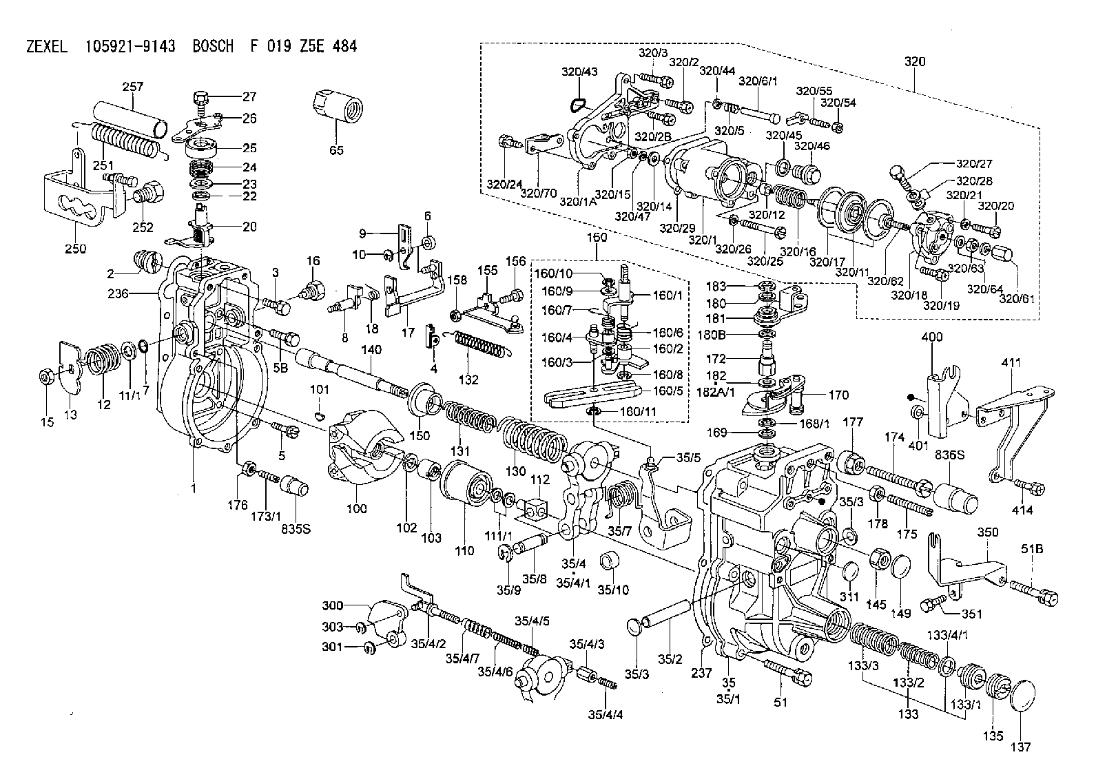
| 1. | [1] | 159200-8820 | GOVERNOR HOUSING |
| 2. | [1] | 154007-0200 | ADAPTOR |
| 3. | [1] | 020018-1840 | BLEEDER SCREW |
| 4. | [1] | 159232-1600 | PLATE |
| 5. | [5] | 029010-6810 | BLEEDER SCREW |
| 5B. | [1] | 020106-1640 | BLEEDER SCREW |
| 6. | [1] | 159242-0600 | BUSHING |
| 7. | [1] | 016530-1010 | O-RING |
| 8. | [1] | 159205-2821 | LEVER SHAFT |
| 9. | [1] | 159202-7500 | CONTROL LEVER |
| 10. | [1] | 016010-0810 | LOCKING WASHER |
| 11/1. | [0] | 029311-0220 | SHIM D18&10.3T0.2 |
| 11/1. | [0] | 029311-0230 | SHIM D18&10.3T0.5 |
| 11/1. | [0] | 029311-0430 | SHIM D18&10.3T0.30 |
| 11/1. | [0] | 029311-0440 | SHIM D18&10.3T0.40 |
| 11/1. | [0] | 029311-0450 | SHIM D18&10.3T0.25 |
| 11/1. | [0] | 029311-0460 | SHIM D18&10.3T0.35 |
| 11/1. | [0] | 139410-3300 | SHIM D18&10.3T0.6 |
| 11/1. | [0] | 139410-3400 | SHIM D18&10.3T0.8 |
| 11/1. | [0] | 139410-3500 | SHIM D18&10.3T0.9 |
| 12. | [1] | 159215-0500 | COILED SPRING |
| 13. | [1] | 159242-6601 | CONTROL LEVER |
| 15. | [1] | 013020-8040 | UNION NUT |
| 16. | [1] | 159237-5500 | CAPSULE |
| 17. | [1] | 159202-4220 | CONTROL LEVER |
| 18. | [1] | 159215-0600 | COILED SPRING |
| 20. | [1] | 159291-2920 | CONTROL LEVER |
| 22. | [1] | 139610-0400 | PACKING RING |
| 23. | [1] | 139411-0700 | SHIM D22&11T0.7 |
| 23B. | [1] | 153305-0100 | SHIM D22&11T0.5 |
| 24. | [1] | 159215-3100 | COILED SPRING |
| 25. | [1] | 159235-5800 | CAP |
| 26. | [1] | 159291-6720 | CONTROL LEVER |
| 27. | [1] | 020006-1640 | BLEEDER SCREW |
| 35. | [1] | 159255-1220 | GOVERNOR COVER |
| 35/1. | [1] | 159201-5521 | GOVERNOR COVER |
| 35/2. | [1] | 159205-0400 | LEVER SHAFT |
| 35/3. | [2] | 159237-0200 | CAPSULE |
| 35/3. | [2] | 159237-0200 | CAPSULE |
| 35/4. | [1] | 159253-1520 | TENSIONING LEVER |
| 35/4/1. | [1] | 159203-1420 | TENSIONING LEVER |
| 35/4/2. | [1] | 159204-6322 | RACK |
| 35/4/3. | [1] | 159233-0300 | UNION NUT |
| 35/4/4. | [1] | 159234-0300 | FLAT-HEAD SCREW |
| 35/4/5. | [1] | 159216-0000 | COILED SPRING |
| 35/4/6. | [1] | 159216-0100 | COILED SPRING |
| 35/4/7. | [1] | 159216-0700 | COILED SPRING |
| 35/5. | [1] | 159203-6220 | GUIDE LEVER |
| 35/7. | [1] | 159215-1701 | COILED SPRING |
| 35/8. | [1] | 159231-1300 | BEARING PIN |
| 35/9. | [2] | 016010-0610 | LOCKING WASHER |
| 35/10. | [1] | 159238-2900 | BUSHING |
| 51. | [6] | 020106-3840 | BLEEDER SCREW |
| 51B. | [1] | 020106-4540 | BLEEDER SCREW |
| 65. | [1] | 155404-5700 | CAP |
| 100. | [1] | 154100-9520 | FLYWEIGHT ASSEMBLY |
| 101. | [1] | 025803-1610 | WOODRUFF KEY 16 MM |
| 102. | [1] | 029321-2020 | LOCKING WASHER |
| 103. | [1] | 029231-2030 | UNION NUT |
| 110. | [1] | 154123-2320 | SLIDING PIECE |
| 111/1. | [0] | 029311-0010 | SHIM D14&10.1T0.2 |
| 111/1. | [0] | 029311-0180 | SHIM D14&10.1T0.3 |
| 111/1. | [0] | 029311-0190 | SHIM D14&10.1T0.40 |
| 111/1. | [0] | 029311-0210 | SHIM D14&10.1T1 |
| 111/1. | [0] | 139410-0000 | SHIM D14&10.1T0.5 |
| 111/1. | [0] | 139410-0100 | SHIM D14&10.1T1.5 |
| 111/1. | [0] | 139410-3000 | SHIM D14&10.1T2.0 |
| 111/1. | [0] | 139410-3100 | SHIM D14&10.1T3.0 |
| 111/1. | [0] | 139410-3200 | SHIM D14&10.1T4.0 |
| 112. | [1] | 159236-0200 | TERMINAL STUD |
| 130. | [1] | 159210-8200 | GOVERNOR SPRING |
| 131. | [1] | 159211-3400 | GOVERNOR SPRING |
| 132. | [1] | 159214-0300 | COILED SPRING |
| 133. | [1] | 159219-3620 | SPRING PACK |
| 133/1. | [1] | 159234-5602 | GUIDE SLEEVE |
| 133/2. | [1] | 159212-5500 | COILED SPRING |
| 133/3. | [1] | 159212-5300 | COILED SPRING |
| 133/4/1. | [0] | 029310-9240 | SHIM D11.9&9T0.1 |
| 133/4/1. | [0] | 029310-9250 | SHIM D11.9&9T0.2 |
| 133/4/1. | [0] | 029310-9260 | SHIM D11.9&9T0.25 |
| 133/4/1. | [0] | 029310-9270 | SHIM D11.9&9T1.0 |
| 133/4/1. | [0] | 139409-0100 | SHIM D11.9&9T0.3 |
| 133/4/1. | [0] | 139409-0200 | SHIM D11.9&9T0.5 |
| 133/4/1. | [0] | 139409-0300 | SHIM D11.5&9T0.8 |
| 135. | [1] | 159248-2700 | FLAT-HEAD SCREW |
| 137. | [1] | 159237-5300 | CAPSULE |
| 140. | [1] | 159205-2101 | LEVER SHAFT |
| 145. | [1] | 159233-5700 | UNION NUT |
| 149. | [1] | 159237-5400 | CAPSULE |
| 150. | [1] | 159235-5300 | SLOTTED WASHER |
| 155. | [1] | 159204-7520 | STRAP |
| 156. | [1] | 159233-0620 | BLEEDER SCREW |
| 158. | [1] | 013020-5240 | UNION NUT |
| 160. | [1] | 159252-2321 | LEVER GROUP |
| 160/1. | [1] | 159205-3921 | LEVER SHAFT |
| 160/2. | [1] | 159202-4420 | CONTROL LEVER |
| 160/3. | [1] | 029310-6030 | SHIM |
| 160/4. | [1] | 159202-4520 | CONTROL LEVER |
| 160/5. | [1] | 159202-2200 | CONTROL LEVER |
| 160/6. | [1] | 159215-2600 | COILED SPRING |
| 160/7. | [1] | 159215-3600 | COILED SPRING |
| 160/8. | [1] | 016010-0810 | LOCKING WASHER |
| 160/9. | [1] | 014020-6140 | PLAIN WASHER D11.5&6.5 |
| 160/10. | [1] | 016010-0610 | LOCKING WASHER |
| 160/11. | [1] | 016010-0810 | LOCKING WASHER |
| 168/1. | [0] | 029311-0640 | SHIM D26.0&10.2T0.95 |
| 168/1. | [0] | 029311-0650 | SHIM D26.0&10.2T0.20 |
| 168/1. | [0] | 029311-0660 | SHIM D26.0&10.2T0.25 |
| 168/1. | [0] | 029311-0670 | SHIM D26.0&10.2T0.30 |
| 168/1. | [0] | 029311-0680 | SHIM D26.0&10.2T0.35 |
| 168/1. | [0] | 029311-0690 | SHIM D26.0&10.2T0.40 |
| 168/1. | [0] | 029311-0700 | SHIM D26.0&10.2T0.50 |
| 168/1. | [0] | 139410-1400 | SHIM D26&10.2T0.7 |
| 168/1. | [0] | 139410-1500 | SHIM D26&10.2T0.9 |
| 168/1. | [0] | 139410-1600 | SHIM D26&10.2T0.8 |
| 168/1. | [0] | 139410-2700 | SHIM D26&10.2T0.6 |
| 169. | [1] | 139410-2300 | SHIM |
| 170. | [1] | 159269-5720 | CONTROL LEVER |
| 172. | [1] | 159233-7100 | UNION NUT |
| 173/1. | [1] | 139006-3500 | BLEEDER SCREW M6P1.0L33 |
| 173/1. | [1] | 139006-3700 | BLEEDER SCREW M6P1.0L34 |
| 173/1. | [1] | 139006-3800 | BLEEDER SCREW M6P1.0L35 |
| 173/1. | [1] | 139006-3900 | BLEEDER SCREW M6P1.0L36 |
| 173/1. | [1] | 139006-5300 | BLEEDER SCREW M6P1.0L31 |
| 173/1. | [1] | 139006-5400 | BLEEDER SCREW M6P1.0L32 |
| 173/1. | [1] | 155615-2500 | BLEEDER SCREW M6P1.0L37 |
| 174. | [1] | 154010-7200 | BLEEDER SCREW |
| 175. | [1] | 154013-1600 | FLAT-HEAD SCREW |
| 176. | [1] | 159225-8600 | UNION NUT |
| 177. | [1] | 154011-2300 | UNION NUT |
| 178. | [1] | 154011-2800 | UNION NUT |
| 180. | [2] | 154371-0000 | PLAIN WASHER |
| 180B. | [1] | 139408-1000 | SHIM |
| 181. | [1] | 159269-9720 | CONTROL LEVER |
| 182. | [1] | 139408-1000 | SHIM |
| 182A/1. | [0] | 139408-1000 | SHIM D16&8T0.5 |
| 182A/1. | [0] | 139408-1300 | SHIM D16&8T0.2 |
| 183. | [1] | 016010-0740 | LOCKING WASHER |
| 236. | [1] | 154390-0000 | GASKET |
| 237. | [1] | 159238-3100 | GASKET |
| 250. | [1] | 159221-1320 | BRACKET |
| 251. | [3] | 159243-4700 | COILED SPRING |
| 252. | [1] | 159248-0200 | BLEEDER SCREW |
| 257. | [3] | 154156-0500 | TUBE |
| 300. | [1] | 159288-3200 | CAM PLATE |
| 301. | [1] | 016010-0840 | LOCKING WASHER |
| 303. | [1] | 016010-0540 | LOCKING WASHER |
| 311. | [1] | 159237-0200 | CAPSULE |
| 320. | [1] | 154422-8620 | MANIFOLD-PRESSURE COMP. |
| 320/1. | [1] | 154408-9520 | GOVERNOR HOUSING |
| 320/1A. | [1] | 154412-8600 | SPACER BUSHING |
| 320/2. | [2] | 020106-2840 | BLEEDER SCREW |
| 320/2B. | [1] | 020106-2540 | BLEEDER SCREW |
| 320/3. | [1] | 020118-2840 | BLEEDER SCREW |
| 320/5. | [1] | 159275-1400 | COILED SPRING |
| 320/6/1. | [1] | 159274-0120 | STOP PIN L125 |
| 320/6/1. | [1] | 159274-0220 | STOP PIN L127.50 |
| 320/6/1. | [1] | 159274-0320 | STOP PIN L128.00 |
| 320/6/1. | [1] | 159274-0420 | STOP PIN L127.00 |
| 320/6/1. | [1] | 159274-0520 | STOP PIN L126.00 |
| 320/6/1. | [1] | 159274-0620 | STOP PIN L129.00 |
| 320/6/1. | [1] | 159274-0720 | STOP PIN L128.50 |
| 320/6/1. | [1] | 159274-0820 | STOP PIN L125.50 |
| 320/6/1. | [1] | 159274-0920 | STOP PIN L126.50 |
| 320/6/1. | [1] | 159274-1120 | STOP PIN L119.5 |
| 320/6/1. | [1] | 159274-1220 | STOP PIN L120 |
| 320/6/1. | [1] | 159274-1320 | STOP PIN L120.5 |
| 320/6/1. | [1] | 159274-1420 | STOP PIN L121 |
| 320/6/1. | [1] | 159274-1520 | STOP PIN L121.5 |
| 320/6/1. | [1] | 159274-1620 | STOP PIN L122 |
| 320/6/1. | [1] | 159274-1720 | STOP PIN L122.5 |
| 320/6/1. | [1] | 159274-1820 | STOP PIN L123 |
| 320/6/1. | [1] | 159274-1920 | STOP PIN L123.5 |
| 320/6/1. | [1] | 159274-4220 | STOP PIN L129.5 |
| 320/6/1. | [1] | 159274-4320 | STOP PIN L130 |
| 320/6/1. | [1] | 159274-4420 | STOP PIN L130.5 |
| 320/6/1. | [1] | 159274-4520 | STOP PIN L131 |
| 320/6/1. | [1] | 159274-4620 | STOP PIN L131.5 |
| 320/6/1. | [1] | 159274-4720 | STOP PIN L132 |
| 320/6/1. | [1] | 159274-4820 | STOP PIN L132.5 |
| 320/6/1. | [1] | 159274-4920 | STOP PIN L133 |
| 320/6/1. | [1] | 159274-5020 | STOP PIN L133.5 |
| 320/11. | [1] | 154400-8521 | DIAPHRAGM |
| 320/12. | [1] | 154413-1400 | BUSHING |
| 320/14. | [1] | 154406-5500 | SLOTTED WASHER |
| 320/15. | [1] | 013030-6040 | UNION NUT |
| 320/16. | [1] | 154416-0100 | COILED SPRING |
| 320/17. | [2] | 154413-2600 | GASKET |
| 320/18. | [1] | 154404-5100 | COVER |
| 320/19. | [1] | 020106-2040 | BLEEDER SCREW |
| 320/20. | [2] | 139006-7000 | BLEEDER SCREW |
| 320/21. | [2] | 014110-6440 | LOCKING WASHER D12.2&6.1T1.5 |
| 320/24. | [3] | 020106-2540 | BLEEDER SCREW |
| 320/25. | [1] | 139006-1300 | BLEEDER SCREW |
| 320/26. | [1] | 029320-6010 | LOCKING WASHER |
| 320/27. | [1] | 029731-0180 | EYE BOLT |
| 320/28. | [2] | 026510-1340 | GASKET |
| 320/29. | [1] | 154413-2800 | GASKET |
| 320/43. | [1] | 159226-4500 | SPACER RING |
| 320/44. | [1] | 014010-5140 | PLAIN WASHER |
| 320/45. | [1] | 029331-8040 | GASKET |
| 320/46. | [1] | 154406-5800 | FLAT-HEAD SCREW |
| 320/47. | [1] | 014110-6440 | LOCKING WASHER D12.2&6.1T1.5 |
| 320/54. | [1] | 013030-6040 | UNION NUT |
| 320/55. | [1] | 154404-4800 | FLAT-HEAD SCREW |
| 320/61. | [1] | 154035-1600 | CAP NUT |
| 320/62. | [1] | 154404-4400 | FLAT-HEAD SCREW |
| 320/63. | [1] | 013030-6040 | UNION NUT |
| 320/64. | [2] | 026506-1040 | GASKET |
| 320/70. | [1] | 159245-5420 | BRACKET |
| 350. | [1] | 159223-2000 | BRACKET |
| 351. | [1] | 020106-1040 | BLEEDER SCREW M6P1.0L12 |
| 400. | [1] | 159223-2100 | BRACKET |
| 401. | [1] | 159227-5600 | BUSHING |
| 411. | [1] | 159222-6220 | BRACKET |
| 414. | [1] | 020106-1240 | BLEEDER SCREW |
| 835S. | [1] | 154062-1900 | CAP |
| 836S. | [1] | 154062-1700 | CAP |
Include in #1:
101401-9834
as GOVERNOR
Cross reference number
Zexel num
Bosch num
Firm num
Name
Information:
GENERAL
Specification
Construction
Governor System Component Parts(1) Sealing metal(2) Sealing wire(3) Low- and high-speed(4) Governor spring(5) Sliding shaft(6) Stopper(7) Governor spring(8) Governor shaft(9) Governor lever(10) Tie-rod(11) Tie-rod clip(12) Tie-rod cover(13) tie-rod cover gasket(14) Tension lever(15) Start spring(16) Governor spring lever(17) Speed control lever assembly(18) Cover assembly(19) Governor cover gasket(20) Return spring(21) Stop lever assembly(22) O-ring(23) Snap ring(24) Stop lever(25) Grooved pin (3 x 20)(26) Grooved pin (3 x 14)(27) Torque spring set(28) Sealing capTORQUE SPRING
Installation of Torque Spring Set
Install and adjust the torque spring set using the following procedure:(1) Set the speed control lever to the high-idling speed position by adjusting the high-speed set bolt.(2) Turn in the torque spring set until engine speed drops about 50 rpm from high-idling speed.(3) From this position, turn back the torque spring set by the specified number of turns (N.) Lock the torque spring set at that position with the special nut.(4) Install the torque spring set sealing cap and stake the cap to prevent loosening. CAUTION There are two types of torque spring set: The single spring type and the double-spring type. Since each torque spring set has been adjusted precisely during assembly, do not tamper with the adjust screw unless it is necessary.
Torque spring setAssembling the Torque Spring Set
When the torque spring set has been disassembled or its component parts have been replaced, reassemble and adjust the torque spring set using the following procedure:
Assembling torque spring setSingle spring type
When installing the single-spring type torque spring set, use the following steps.(1) Lightly turn in adjust screw (5) (with a screw-driver operated by fingertips) until a resistance to screw rotation is felt. Lightly lock the screw at that position with locknut (4).(2) Set the scale to the zero-point. Turn in the spring case (2) until the value of load "A" shown in table below can be attained. Lock the spring case at that position with special nut (3).(3) Temporarily loosen adjust screw (5) until the value of load "A" is reduced by about 200 grams, and then retighten the screw until the value of "B" is attained. Lock the screw at that position with locknut (4).Adjust screw tightening torque: 0.8 to 1.2 kg.(4) To inspect the torque spring set for properly adjusted spring load, use a testing arrangement such as shown in the figure at right. Gradually push the scale against the torque spring set until the stopper (1) is moved (or the pointer of dial gauge deflects). Check that the load applied to the torque spring at that moment coincides with the value of load "C".
Setting of Torque Spring CHECKING
Replace the gear case and inspect the governor. When removing the gear case, be sure to remove the tie-rod cover by the side of the fuel pump and disconnect the tie-rod from the rack.If any parts are found defective, replace them.
Inspecting Torque Spring CAUTION When the governor is assumed to be malfunctioning, check the bearing on the gear case side, too.
Inspection Governor System PartsRemoval and Installation
(Refer to I-06 GEAR CASE AND OIL PUMP.)Removal(1) Removing