Information governor
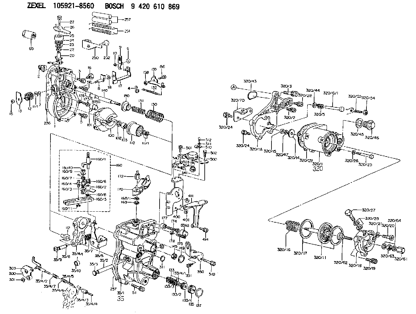
BOSCH
9 420 610 869
9420610869
ZEXEL
105921-8560
1059218560
Rating:
Scheme ###:
| 1. | [1] | 159200-8820 | GOVERNOR HOUSING |
| 2. | [1] | 154007-0200 | ADAPTOR |
| 3. | [1] | 020018-1840 | BLEEDER SCREW M8P1.25L18 |
| 4. | [1] | 159232-1600 | PLATE |
| 5. | [5] | 029010-6810 | BLEEDER SCREW |
| 5B. | [1] | 020106-1640 | BLEEDER SCREW M6P1.0L14 |
| 6. | [1] | 159242-0600 | BUSHING |
| 7. | [1] | 016530-1010 | O-RING |
| 8. | [1] | 159205-2821 | LEVER SHAFT |
| 9. | [1] | 159202-7500 | CONTROL LEVER |
| 10. | [1] | 016010-0810 | LOCKING WASHER |
| 11/1. | [0] | 029311-0220 | SHIM D18&10.3T0.2 |
| 11/1. | [0] | 029311-0230 | SHIM D18&10.3T0.5 |
| 11/1. | [0] | 029311-0430 | SHIM D18&10.3T0.30 |
| 11/1. | [0] | 029311-0440 | SHIM D18&10.3T0.40 |
| 11/1. | [0] | 029311-0450 | SHIM D18&10.3T0.25 |
| 11/1. | [0] | 029311-0460 | SHIM D18&10.3T0.35 |
| 11/1. | [0] | 139410-3300 | SHIM D18&10.3T0.6 |
| 11/1. | [0] | 139410-3400 | SHIM D18&10.3T0.8 |
| 11/1. | [0] | 139410-3500 | SHIM D18&10.3T0.9 |
| 12. | [1] | 159215-0500 | COILED SPRING |
| 13. | [1] | 159242-6601 | CONTROL LEVER |
| 15. | [1] | 013020-8040 | UNION NUT M8P1.25H7 |
| 16. | [1] | 159237-5500 | CAPSULE |
| 17. | [1] | 159202-4220 | CONTROL LEVER |
| 18. | [1] | 159215-0600 | COILED SPRING |
| 20. | [1] | 159291-2920 | CONTROL LEVER |
| 22. | [1] | 139610-0400 | PACKING RING |
| 23. | [1] | 139411-0700 | SHIM D22&11T0.7 |
| 23B. | [1] | 153305-0100 | SHIM D22&11T0.5 |
| 24. | [1] | 159215-3100 | COILED SPRING |
| 25. | [1] | 159235-5800 | CAP |
| 26. | [1] | 159290-6021 | CONTROL LEVER |
| 27. | [1] | 020006-1640 | BLEEDER SCREW M6P1L16 4T |
| 35. | [1] | 159255-1220 | GOVERNOR COVER |
| 35/1. | [1] | 159201-5521 | GOVERNOR COVER |
| 35/2. | [1] | 159205-0400 | LEVER SHAFT |
| 35/3. | [2] | 159237-0200 | CAPSULE |
| 35/4. | [1] | 159253-1520 | TENSIONING LEVER |
| 35/4/1. | [1] | 159203-1420 | TENSIONING LEVER |
| 35/4/2. | [1] | 159204-6322 | RACK |
| 35/4/3. | [1] | 159233-0300 | UNION NUT |
| 35/4/4. | [1] | 159234-0300 | FLAT-HEAD SCREW |
| 35/4/5. | [1] | 159216-0000 | COILED SPRING |
| 35/4/6. | [1] | 159216-0100 | COILED SPRING |
| 35/4/7. | [1] | 159216-0700 | COILED SPRING |
| 35/5. | [1] | 159203-6220 | GUIDE LEVER |
| 35/7. | [1] | 159215-1701 | COILED SPRING |
| 35/8. | [1] | 159231-1300 | BEARING PIN |
| 35/9. | [2] | 016010-0610 | LOCKING WASHER |
| 35/10. | [1] | 159238-2900 | BUSHING |
| 51. | [6] | 020106-3840 | BLEEDER SCREW |
| 51B. | [1] | 020106-4540 | BLEEDER SCREW M6P1.0L45 |
| 65. | [1] | 155404-5700 | CAP |
| 100. | [1] | 154100-9520 | FLYWEIGHT ASSEMBLY |
| 101. | [1] | 025803-1610 | WOODRUFF KEY |
| 102. | [1] | 029321-2020 | LOCKING WASHER |
| 103. | [1] | 029231-2030 | UNION NUT |
| 110. | [1] | 154123-2320 | SLIDING PIECE |
| 111/1. | [0] | 029311-0010 | SHIM D14&10.1T0.2 |
| 111/1. | [0] | 029311-0180 | SHIM D14&10.1T0.3 |
| 111/1. | [0] | 029311-0190 | SHIM D14&10.1T0.40 |
| 111/1. | [0] | 029311-0210 | SHIM D14&10.1T1 |
| 111/1. | [0] | 139410-0000 | SHIM D14.0&10.1T0.5 |
| 111/1. | [0] | 139410-0100 | SHIM D14.0&10.1T1.5 |
| 111/1. | [0] | 139410-3000 | SHIM D14&10.1T2.0 |
| 111/1. | [0] | 139410-3100 | SHIM D14&10.1T3.0 |
| 111/1. | [0] | 139410-3200 | SHIM D14&10.1T4.0 |
| 112. | [1] | 159236-0200 | TERMINAL STUD |
| 130. | [1] | 159210-8200 | GOVERNOR SPRING |
| 131. | [1] | 159211-3400 | GOVERNOR SPRING |
| 132. | [1] | 159214-0300 | COILED SPRING |
| 133. | [1] | 159219-3620 | SPRING PACK |
| 133/1. | [1] | 159234-5602 | GUIDE SLEEVE |
| 133/2. | [1] | 159212-5500 | COILED SPRING |
| 133/3. | [1] | 159212-5300 | COILED SPRING |
| 133/4/1. | [0] | 029310-9240 | SHIM D11.9&9T0.1 |
| 133/4/1. | [0] | 029310-9250 | SHIM D11.9&9T0.2 |
| 133/4/1. | [0] | 029310-9260 | SHIM D11.9&9T0.25 |
| 133/4/1. | [0] | 029310-9270 | SHIM D11.9&9T1.0 |
| 133/4/1. | [0] | 139409-0100 | SHIM D11.9&9T0.3 |
| 133/4/1. | [0] | 139409-0200 | SHIM D11.9&9T0.5 |
| 133/4/1. | [0] | 139409-0300 | SHIM D11.5&9T0.8 |
| 135. | [1] | 159248-2700 | FLAT-HEAD SCREW |
| 137. | [1] | 159237-5300 | CAPSULE |
| 140. | [1] | 159205-2101 | LEVER SHAFT |
| 145. | [1] | 159233-5700 | UNION NUT |
| 149. | [1] | 159237-5400 | CAPSULE |
| 150. | [1] | 159235-5300 | SLOTTED WASHER |
| 155. | [1] | 159204-7520 | STRAP |
| 156. | [1] | 159233-0620 | BLEEDER SCREW |
| 158. | [1] | 013020-5240 | UNION NUT M5P0.8H4 |
| 160. | [1] | 159252-3520 | LEVER GROUP |
| 160/1. | [1] | 159205-5120 | LEVER SHAFT |
| 160/2. | [1] | 159202-4420 | CONTROL LEVER |
| 160/3. | [1] | 029310-6030 | SHIM D11.5&6.2T0.2 |
| 160/4. | [1] | 159202-4520 | CONTROL LEVER |
| 160/5. | [1] | 159202-2200 | CONTROL LEVER |
| 160/6. | [1] | 159215-2600 | COILED SPRING |
| 160/7. | [1] | 159215-3600 | COILED SPRING |
| 160/8. | [1] | 016010-0810 | LOCKING WASHER |
| 160/9. | [1] | 014020-6140 | PLAIN WASHER |
| 160/10. | [1] | 016010-0610 | LOCKING WASHER |
| 160/11. | [1] | 016010-0810 | LOCKING WASHER |
| 168/1. | [0] | 029311-0640 | SHIM D26.0&10.2T0.95 |
| 168/1. | [0] | 029311-0650 | SHIM D26.0&10.2T0.20 |
| 168/1. | [0] | 029311-0660 | SHIM D26.0&10.2T0.25 |
| 168/1. | [0] | 029311-0670 | SHIM D26.0&10.2T0.30 |
| 168/1. | [0] | 029311-0680 | SHIM D26.0&10.2T0.35 |
| 168/1. | [0] | 029311-0690 | SHIM D26.0&10.2T0.40 |
| 168/1. | [0] | 029311-0700 | SHIM D26.0&10.2T0.50 |
| 168/1. | [0] | 139410-1400 | SHIM D26&10.2T0.7 |
| 168/1. | [0] | 139410-1500 | SHIM D26&10.2T0.9 |
| 168/1. | [0] | 139410-1600 | SHIM D26&10.2T0.8 |
| 168/1. | [0] | 139410-2700 | SHIM D26&10.2T0.6 |
| 169. | [1] | 139410-2300 | SHIM |
| 170. | [1] | 159265-0420 | CONTROL LEVER |
| 172. | [1] | 159233-6800 | UNION NUT |
| 173/1. | [1] | 139006-3500 | BLEEDER SCREW M6P1.0L33 |
| 173/1. | [1] | 139006-3700 | BLEEDER SCREW M6P1.0L34 |
| 173/1. | [1] | 139006-3800 | BLEEDER SCREW M6P1.0L35 |
| 173/1. | [1] | 139006-3900 | BLEEDER SCREW M6P1.0L36 |
| 173/1. | [1] | 139006-5300 | BLEEDER SCREW M6P1.0L31 |
| 173/1. | [1] | 139006-5400 | BLEEDER SCREW M6P1.0L32 |
| 173/1. | [1] | 155615-2500 | BLEEDER SCREW M6P1.0L37 |
| 174. | [1] | 154010-7200 | BLEEDER SCREW M8P1.25L62 |
| 175. | [1] | 154013-1600 | FLAT-HEAD SCREW |
| 176. | [1] | 159225-8600 | UNION NUT |
| 177. | [1] | 154011-2300 | UNION NUT |
| 178. | [1] | 154011-2800 | UNION NUT |
| 236. | [1] | 154390-0000 | GASKET |
| 237. | [1] | 159238-3100 | GASKET |
| 250. | [1] | 159222-6120 | BRACKET |
| 251. | [2] | 159243-4700 | COILED SPRING |
| 252. | [1] | 159248-0200 | BLEEDER SCREW |
| 257. | [2] | 154156-0500 | TUBE |
| 300. | [1] | 159287-3300 | CAM PLATE |
| 301. | [1] | 016010-0840 | LOCKING WASHER |
| 303. | [1] | 016010-0540 | LOCKING WASHER |
| 311. | [1] | 159237-0200 | CAPSULE |
| 320. | [1] | 154421-2820 | MANIFOLD-PRESSURE COMP. |
| 320/1. | [1] | 154408-9520 | GOVERNOR HOUSING |
| 320/1A. | [1] | 154412-8600 | SPACER BUSHING |
| 320/2. | [2] | 020106-2840 | BLEEDER SCREW |
| 320/2B. | [1] | 020106-2540 | BLEEDER SCREW M6P1L25 |
| 320/3. | [1] | 020118-2840 | BLEEDER SCREW |
| 320/5. | [1] | 159275-1400 | COILED SPRING |
| 320/6/1. | [1] | 159274-0120 | STOP PIN L125 |
| 320/6/1. | [1] | 159274-0220 | STOP PIN L127.50 |
| 320/6/1. | [1] | 159274-0320 | STOP PIN L128.00 |
| 320/6/1. | [1] | 159274-0420 | STOP PIN L127.00 |
| 320/6/1. | [1] | 159274-0520 | STOP PIN L126.00 |
| 320/6/1. | [1] | 159274-0620 | STOP PIN L129.00 |
| 320/6/1. | [1] | 159274-0720 | STOP PIN L128.50 |
| 320/6/1. | [1] | 159274-0820 | STOP PIN L125.50 |
| 320/6/1. | [1] | 159274-0920 | STOP PIN L126.50 |
| 320/6/1. | [1] | 159274-1120 | STOP PIN L119.5 |
| 320/6/1. | [1] | 159274-1220 | STOP PIN L120 |
| 320/6/1. | [1] | 159274-1320 | STOP PIN L120.5 |
| 320/6/1. | [1] | 159274-1420 | STOP PIN L121 |
| 320/6/1. | [1] | 159274-1520 | STOP PIN L121.5 |
| 320/6/1. | [1] | 159274-1620 | STOP PIN L122 |
| 320/6/1. | [1] | 159274-1720 | STOP PIN L122.5 |
| 320/6/1. | [1] | 159274-1820 | STOP PIN L123 |
| 320/6/1. | [1] | 159274-1920 | STOP PIN L123.5 |
| 320/6/1. | [1] | 159274-4220 | STOP PIN L129.5 |
| 320/6/1. | [1] | 159274-4320 | STOP PIN L130 |
| 320/6/1. | [1] | 159274-4420 | STOP PIN L130.5 |
| 320/6/1. | [1] | 159274-4520 | STOP PIN L131 |
| 320/6/1. | [1] | 159274-4620 | STOP PIN L131.5 |
| 320/6/1. | [1] | 159274-4720 | STOP PIN L132 |
| 320/6/1. | [1] | 159274-4820 | STOP PIN L132.5 |
| 320/6/1. | [1] | 159274-4920 | STOP PIN L133 |
| 320/6/1. | [1] | 159274-5020 | STOP PIN L133.5 |
| 320/11. | [1] | 154400-8521 | DIAPHRAGM |
| 320/14. | [1] | 154406-5500 | SLOTTED WASHER |
| 320/15. | [1] | 013030-6010 | UNION NUT |
| 320/16. | [1] | 154411-9900 | COILED SPRING |
| 320/17. | [2] | 154413-2600 | GASKET |
| 320/18. | [1] | 154404-5100 | COVER |
| 320/19. | [1] | 020106-2040 | BLEEDER SCREW M6P1L20 |
| 320/20. | [2] | 139006-7000 | BLEEDER SCREW |
| 320/21. | [2] | 014110-6440 | LOCKING WASHER |
| 320/24. | [3] | 020106-2540 | BLEEDER SCREW M6P1L25 |
| 320/24. | [3] | 020106-2540 | BLEEDER SCREW M6P1L25 |
| 320/25. | [1] | 139006-1300 | BLEEDER SCREW M6P1L76 |
| 320/26. | [1] | 029320-6010 | LOCKING WASHER |
| 320/27. | [1] | 029731-0180 | EYE BOLT |
| 320/28. | [2] | 026510-1340 | GASKET D13.4&10.2T1 |
| 320/29. | [1] | 154413-2800 | GASKET |
| 320/43. | [1] | 159226-4500 | SPACER RING |
| 320/44. | [1] | 014010-5140 | PLAIN WASHER D12&5.5T0.8 |
| 320/45. | [1] | 029331-8040 | GASKET |
| 320/46. | [1] | 154406-5800 | FLAT-HEAD SCREW |
| 320/47. | [1] | 014110-6440 | LOCKING WASHER |
| 320/54. | [1] | 013030-6040 | UNION NUT M6P1H3.6 |
| 320/55. | [1] | 154404-4800 | FLAT-HEAD SCREW |
| 320/61. | [1] | 154035-1600 | CAP NUT |
| 320/62. | [1] | 154404-4400 | FLAT-HEAD SCREW |
| 320/63. | [1] | 013030-6040 | UNION NUT M6P1H3.6 |
| 320/64. | [2] | 026506-1040 | GASKET D9.9&6.2T1 |
| 320/70. | [1] | 159245-5420 | BRACKET |
| 340. | [1] | 159220-5800 | BRACKET |
| 341. | [2] | 020104-1040 | BLEEDER SCREW |
| 350. | [1] | 159220-6000 | BRACKET |
| 351. | [1] | 020106-1040 | BLEEDER SCREW M6P1L12 |
| 400. | [1] | 159220-5600 | BRACKET |
| 401. | [1] | 159227-5600 | BUSHING |
| 411. | [1] | 159222-6220 | BRACKET |
| 414. | [1] | 020106-1240 | BLEEDER SCREW M6P1.0L12 |
| 500. | [1] | 154602-1720 | LOAD SENSOR ASSY |
| 501. | [1] | 020106-1240 | BLEEDER SCREW M6P1.0L12 |
| 502. | [2] | 020105-1240 | BLEEDER SCREW M5P0.8L12 |
| 503. | [1] | 154413-1100 | JOINT CONNECTION |
| 504. | [1] | 154604-8200 | BOOT |
| 510. | [1] | 154604-0200 | CLAMPING BAND |
| 511. | [1] | 014020-4140 | PLAIN WASHER D8&4.5T0.5 |
| 512. | [1] | 012154-1040 | FLAT-HEAD SCREW M4P0.7L10 |
Include in #1:
101401-9670
as GOVERNOR
Cross reference number
Zexel num
Bosch num
Firm num
Name
Information:
Vertical Tachometer Drive
Removal
Fig. 1-Vertical Tachometer DriveRemove cap (1, Fig. 1). Lift gasket (2) out of adapter (3).Turn adapter counterclockwise to remove it. Remove aluminum washer (4). Lift pinion (5) out of flywheel housing (6).Repair
Inspect parts for damage. Replace damaged parts.Installation
Coat pinion with engine oil. Put pinion in flywheel housing so that end of pinion rests on machined pad (7) in flywheel housing. Make sure gear teeth on pinion engage teeth on drive gear. IMPORTANT: Adapter can be installed easily only if gears are in mesh.Put aluminum washer over bottom of adapter. Install adapter in flywheel housing. Tighten adapter securely.Flywheel
Removal
If engine is equipped with a clutch, remove the clutch (Group 4052).
Fig. 2-Flywheel Cap ScrewRemove two cap screws (1, Fig. 2) that hold flywheel on crankshaft. Install two pilot studs through flywheel into crankshaft. Tighten pilot studs securely.
Flywheel weighs 50 to 85 lb. (23 to 39 kg). Plan proper handling procedures to avoid injury.
Remove remaining cap screws (2) that hold flywheel on crankshaft.Install two of the cap screws removed in threaded holes in flywheel. Tighten cap screws evenly to push flywheel off crankshaft.Repair
If engine is equipped with a clutch, inspect clutch contact face on flywheel for scoring, overheating, and cracking.
Fig. 3-Flywheel ThicknessClutch contact face can be resurfaced if there is heat checking. Minimum thickness of flywheel at clutch contact face is: IMPORTANT: If heat checks or cracks can be seen after resurfacing flywheel to minimum thickness, install a new flywheel.Inspect ring gear for worn or broken teeth. If damaged, install a new one (Group 0433).Installation
Install two guide studs in crankshaft rear flange. Tighten guide studs securely.
Flywheel weighs 50 to 85 lb. (23 to 39 kg). Plan proper handling procedure to avoid injury.
Move flywheel into position on guide studs. Push flywheel against crankshaft. IMPORTANT: Install new cap screws each time flywheel is removed.
Fig. 4-Flywheel Cap ScrewInstall cap screws and washers. Tighten cap screws evenly to secure flywheel to crankshaft.Remove guide studs from crankshaft. Install remaining cap screws. Tighten cap screws to 120 lb-ft (163 N m).Install clutch, if used (Group 4052).Flywheel Ring Gear
Removal
Remove flywheel (Group 0433).
Fig. 5-Remove Ring GearSelect a hardwood block (1, Fig. 5) that is slightly smaller than the inside diameter of the ring gear (2). Lay the flywheel, crankshaft side down, on the hardwood block.Using a drift and hammer (3), drive the ring gear off the flywheel. Move drift and hammer around ring gear often to prevent cocking the gear on the flywheel.Installation
Oil fumes or oil can ignite above 380°F (193°C). Use a thermometer and do not exceed 360°F (182°C). Do not allow a flame or heating element to be in direct contact with the oil. Heat the oil in a well-ventilated area. Plan a safe handling procedure to avoid burns.
Fig. 6-ChamferHeat new ring gear evenly in oil (to 360°F [182°C] maximum) or in oven (to 450°F [232°C] maximum) and install hot, with ring gear tooth chamfer (Fig. 6) toward engine side of flywheel. Drive ring gear onto flywheel evenly until it bottoms all the way around on
Removal
Fig. 1-Vertical Tachometer DriveRemove cap (1, Fig. 1). Lift gasket (2) out of adapter (3).Turn adapter counterclockwise to remove it. Remove aluminum washer (4). Lift pinion (5) out of flywheel housing (6).Repair
Inspect parts for damage. Replace damaged parts.Installation
Coat pinion with engine oil. Put pinion in flywheel housing so that end of pinion rests on machined pad (7) in flywheel housing. Make sure gear teeth on pinion engage teeth on drive gear. IMPORTANT: Adapter can be installed easily only if gears are in mesh.Put aluminum washer over bottom of adapter. Install adapter in flywheel housing. Tighten adapter securely.Flywheel
Removal
If engine is equipped with a clutch, remove the clutch (Group 4052).
Fig. 2-Flywheel Cap ScrewRemove two cap screws (1, Fig. 2) that hold flywheel on crankshaft. Install two pilot studs through flywheel into crankshaft. Tighten pilot studs securely.
Flywheel weighs 50 to 85 lb. (23 to 39 kg). Plan proper handling procedures to avoid injury.
Remove remaining cap screws (2) that hold flywheel on crankshaft.Install two of the cap screws removed in threaded holes in flywheel. Tighten cap screws evenly to push flywheel off crankshaft.Repair
If engine is equipped with a clutch, inspect clutch contact face on flywheel for scoring, overheating, and cracking.
Fig. 3-Flywheel ThicknessClutch contact face can be resurfaced if there is heat checking. Minimum thickness of flywheel at clutch contact face is: IMPORTANT: If heat checks or cracks can be seen after resurfacing flywheel to minimum thickness, install a new flywheel.Inspect ring gear for worn or broken teeth. If damaged, install a new one (Group 0433).Installation
Install two guide studs in crankshaft rear flange. Tighten guide studs securely.
Flywheel weighs 50 to 85 lb. (23 to 39 kg). Plan proper handling procedure to avoid injury.
Move flywheel into position on guide studs. Push flywheel against crankshaft. IMPORTANT: Install new cap screws each time flywheel is removed.
Fig. 4-Flywheel Cap ScrewInstall cap screws and washers. Tighten cap screws evenly to secure flywheel to crankshaft.Remove guide studs from crankshaft. Install remaining cap screws. Tighten cap screws to 120 lb-ft (163 N m).Install clutch, if used (Group 4052).Flywheel Ring Gear
Removal
Remove flywheel (Group 0433).
Fig. 5-Remove Ring GearSelect a hardwood block (1, Fig. 5) that is slightly smaller than the inside diameter of the ring gear (2). Lay the flywheel, crankshaft side down, on the hardwood block.Using a drift and hammer (3), drive the ring gear off the flywheel. Move drift and hammer around ring gear often to prevent cocking the gear on the flywheel.Installation
Oil fumes or oil can ignite above 380°F (193°C). Use a thermometer and do not exceed 360°F (182°C). Do not allow a flame or heating element to be in direct contact with the oil. Heat the oil in a well-ventilated area. Plan a safe handling procedure to avoid burns.
Fig. 6-ChamferHeat new ring gear evenly in oil (to 360°F [182°C] maximum) or in oven (to 450°F [232°C] maximum) and install hot, with ring gear tooth chamfer (Fig. 6) toward engine side of flywheel. Drive ring gear onto flywheel evenly until it bottoms all the way around on