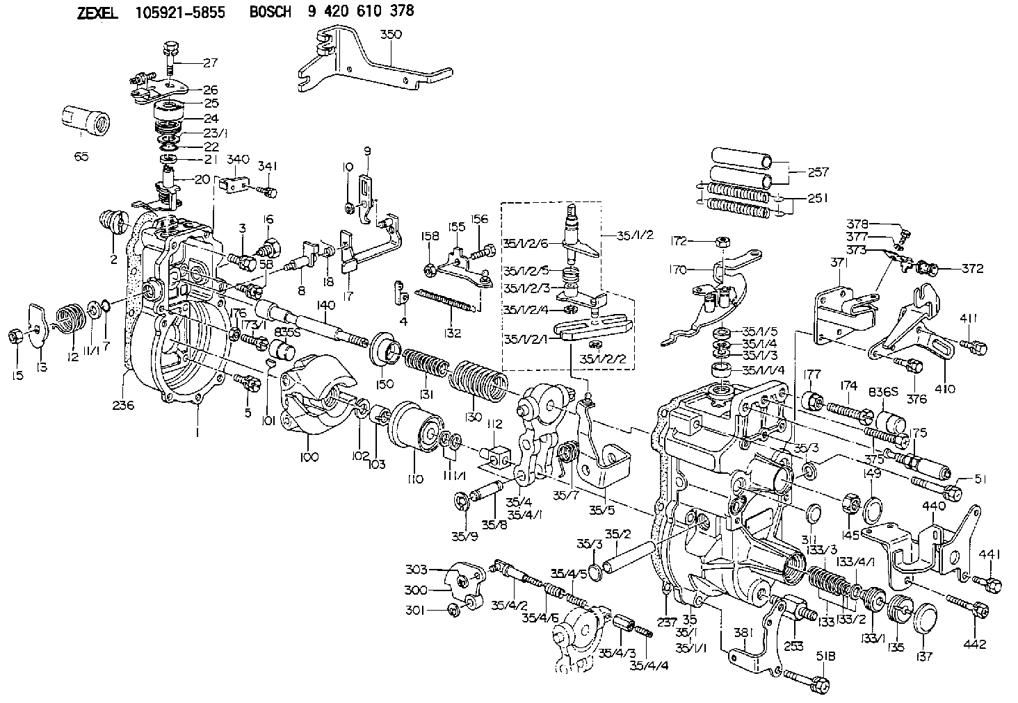
Information governor
BOSCH
9 420 610 378
9420610378
ZEXEL
105921-5855
1059215855
Rating:
Scheme ###:
| 1. | [1] | 159200-3820 | GOVERNOR HOUSING |
| 2. | [1] | 154007-0200 | ADAPTOR |
| 3. | [1] | 020018-1840 | BLEEDER SCREW M8P1.25L18 |
| 4. | [1] | 159232-0401 | PLATE |
| 5. | [5] | 029010-6810 | BLEEDER SCREW |
| 5B. | [1] | 020106-1640 | BLEEDER SCREW M6P1.0L14 |
| 7. | [1] | 016530-1010 | O-RING |
| 8. | [1] | 159205-2821 | LEVER SHAFT |
| 9. | [1] | 159202-4101 | CONTROL LEVER |
| 10. | [1] | 016010-0810 | LOCKING WASHER |
| 11/1. | [0] | 029311-0220 | SHIM D18&10.3T0.2 |
| 11/1. | [0] | 029311-0230 | SHIM D18&10.3T0.5 |
| 11/1. | [0] | 029311-0430 | SHIM D18&10.3T0.30 |
| 11/1. | [0] | 029311-0440 | SHIM D18&10.3T0.40 |
| 11/1. | [0] | 029311-0450 | SHIM D18&10.3T0.25 |
| 11/1. | [0] | 029311-0460 | SHIM D18&10.3T0.35 |
| 11/1. | [0] | 139410-3300 | SHIM D18&10.3T0.6 |
| 11/1. | [0] | 139410-3400 | SHIM D18&10.3T0.8 |
| 11/1. | [0] | 139410-3500 | SHIM D18&10.3T0.9 |
| 12. | [1] | 159215-0500 | COILED SPRING |
| 13. | [1] | 159242-6601 | CONTROL LEVER |
| 15. | [1] | 013020-8040 | UNION NUT M8P1.25H7 |
| 16. | [1] | 159237-5500 | CAPSULE |
| 17. | [1] | 159202-4020 | CONTROL LEVER |
| 18. | [1] | 159215-0600 | COILED SPRING |
| 20. | [1] | 159291-1320 | CONTROL LEVER |
| 21. | [1] | 029311-0210 | SHIM D14&10.1T1 |
| 22. | [1] | 139610-0400 | PACKING RING |
| 23/1. | [0] | 139411-0700 | SHIM D22&11T0.7 |
| 23/1. | [0] | 153305-0100 | SHIM D22&11T0.5 |
| 23/1. | [0] | 153305-0200 | SHIM D22&11T0.4 |
| 23/1. | [0] | 153305-0300 | SHIM D22&11T0.3 |
| 23/1. | [0] | 153305-0400 | SHIM D22&11T0.25 |
| 23/1. | [0] | 153305-0500 | SHIM D22&11T1.0 |
| 23/1. | [0] | 153305-0600 | SHIM D22&11T1.1 |
| 23/1. | [0] | 153305-0700 | SHIM D22&11T2.0 |
| 23/1. | [0] | 153305-1300 | SHIM D22&11T0.951 |
| 23/1. | [0] | 153305-1400 | SHIM D22&11T0.95 |
| 24. | [1] | 159215-3000 | COILED SPRING |
| 25. | [1] | 159235-5800 | CAP |
| 26. | [1] | 159249-9822 | CONTROL LEVER |
| 27. | [1] | 020006-1240 | BLEEDER SCREW M6P1L12 4T |
| 35. | [1] | 159250-2620 | GOVERNOR COVER |
| 35/1. | [1] | 159201-9620 | GOVERNOR COVER |
| 35/1/1. | [1] | 159201-9520 | GOVERNOR COVER |
| 35/1/1/4. | [1] | 159230-2100 | BUSHING |
| 35/1/2. | [1] | 159252-2620 | LEVER GROUP |
| 35/1/2/1. | [1] | 159202-2200 | CONTROL LEVER |
| 35/1/2/2. | [1] | 016010-0810 | LOCKING WASHER |
| 35/1/2/3. | [1] | 159202-3120 | CONTROL LEVER |
| 35/1/2/4. | [1] | 016010-0810 | LOCKING WASHER |
| 35/1/2/5. | [1] | 159215-2600 | COILED SPRING |
| 35/1/2/6. | [1] | 159205-4220 | LEVER SHAFT |
| 35/1/3. | [1] | 139411-0600 | SHIM |
| 35/1/4. | [1] | 159238-3000 | LOCKING WASHER |
| 35/1/5. | [1] | 139610-0500 | PACKING RING |
| 35/2. | [1] | 159205-0400 | LEVER SHAFT |
| 35/3. | [2] | 159237-0200 | CAPSULE |
| 35/3. | [2] | 159237-0200 | CAPSULE |
| 35/4. | [1] | 159253-1120 | TENSIONING LEVER |
| 35/4/1. | [1] | 159203-1120 | TENSIONING LEVER |
| 35/4/2. | [1] | 159204-5021 | RACK |
| 35/4/3. | [1] | 159233-0300 | UNION NUT |
| 35/4/4. | [1] | 159234-0300 | FLAT-HEAD SCREW |
| 35/4/5. | [1] | 159216-0000 | COILED SPRING |
| 35/4/6. | [1] | 159216-0100 | COILED SPRING |
| 35/5. | [1] | 159203-6020 | GUIDE LEVER |
| 35/7. | [1] | 159215-1701 | COILED SPRING |
| 35/8. | [1] | 159231-2000 | BEARING PIN |
| 35/9. | [2] | 016010-0610 | LOCKING WASHER |
| 51. | [4] | 020106-3840 | BLEEDER SCREW |
| 51B. | [3] | 020106-4540 | BLEEDER SCREW M6P1.0L45 |
| 65. | [1] | 155404-6700 | CAP |
| 100. | [1] | 154100-9520 | FLYWEIGHT ASSEMBLY |
| 101. | [1] | 025803-1610 | WOODRUFF KEY |
| 102. | [1] | 029321-2020 | LOCKING WASHER |
| 103. | [1] | 029231-2030 | UNION NUT |
| 110. | [1] | 154123-3820 | SLIDING PIECE |
| 111/1. | [0] | 029311-0010 | SHIM D14&10.1T0.2 |
| 111/1. | [0] | 029311-0180 | SHIM D14&10.1T0.3 |
| 111/1. | [0] | 029311-0190 | SHIM D14&10.1T0.40 |
| 111/1. | [0] | 029311-0210 | SHIM D14&10.1T1 |
| 111/1. | [0] | 139410-0000 | SHIM D14.0&10.1T0.5 |
| 111/1. | [0] | 139410-0100 | SHIM D14.0&10.1T1.5 |
| 111/1. | [0] | 139410-3000 | SHIM D14&10.1T2.0 |
| 111/1. | [0] | 139410-3100 | SHIM D14&10.1T3.0 |
| 111/1. | [0] | 139410-3200 | SHIM D14&10.1T4.0 |
| 112. | [1] | 159236-0200 | TERMINAL STUD |
| 130. | [1] | 159210-3300 | GOVERNOR SPRING |
| 131. | [1] | 159211-3400 | GOVERNOR SPRING |
| 132. | [1] | 159214-0000 | COILED SPRING |
| 133. | [1] | 159212-7920 | SPRING PACK |
| 133/1. | [1] | 159234-5602 | GUIDE SLEEVE |
| 133/2. | [1] | 159212-3300 | COILED SPRING |
| 133/3. | [1] | 159212-7500 | COILED SPRING |
| 133/4/1. | [0] | 029310-9240 | SHIM D11.9&9T0.1 |
| 133/4/1. | [0] | 029310-9250 | SHIM D11.9&9T0.2 |
| 133/4/1. | [0] | 029310-9260 | SHIM D11.9&9T0.25 |
| 133/4/1. | [0] | 029310-9270 | SHIM D11.9&9T1.0 |
| 133/4/1. | [0] | 139409-0100 | SHIM D11.9&9T0.3 |
| 133/4/1. | [0] | 139409-0200 | SHIM D11.9&9T0.5 |
| 133/4/1. | [0] | 139409-0300 | SHIM D11.5&9T0.8 |
| 135. | [1] | 159248-2700 | FLAT-HEAD SCREW |
| 137. | [1] | 159237-5300 | CAPSULE |
| 140. | [1] | 159205-2101 | LEVER SHAFT |
| 145. | [1] | 159233-5700 | UNION NUT |
| 149. | [1] | 159237-5400 | CAPSULE |
| 150. | [1] | 159235-5300 | SLOTTED WASHER |
| 155. | [1] | 159204-5620 | STRAP |
| 156. | [1] | 159233-0520 | BLEEDER SCREW |
| 158. | [1] | 013020-5240 | UNION NUT M5P0.8H4 |
| 170. | [1] | 159265-6120 | CONTROL LEVER |
| 172. | [1] | 013020-8040 | UNION NUT M8P1.25H7 |
| 173/1. | [1] | 139006-7700 | BLEEDER SCREW |
| 173/1. | [1] | 139006-7800 | BLEEDER SCREW |
| 173/1. | [1] | 139006-7900 | BLEEDER SCREW |
| 173/1. | [1] | 139006-8000 | BLEEDER SCREW |
| 173/1. | [1] | 139006-8100 | BLEEDER SCREW |
| 173/1. | [1] | 139006-8200 | BLEEDER SCREW |
| 173/1. | [1] | 139006-8300 | BLEEDER SCREW |
| 174. | [1] | 154012-5600 | BLEEDER SCREW |
| 175. | [1] | 159226-7521 | THERMOSTAT |
| 176. | [1] | 159233-7500 | UNION NUT |
| 177. | [1] | 154011-2300 | UNION NUT |
| 236. | [1] | 154390-0000 | GASKET |
| 237. | [1] | 159238-3100 | GASKET |
| 251. | [2] | 154332-6200 | COILED SPRING |
| 253. | [1] | 159248-3501 | BLEEDER SCREW |
| 257. | [2] | 154156-0600 | TUBE |
| 300. | [1] | 159283-9600 | CAM PLATE |
| 301. | [1] | 016010-0840 | LOCKING WASHER |
| 303. | [1] | 016010-0540 | LOCKING WASHER |
| 311. | [1] | 159237-0200 | CAPSULE |
| 340. | [1] | 159229-0700 | BRACKET |
| 341. | [2] | 020104-1040 | BLEEDER SCREW |
| 350. | [1] | 159228-8000 | BRACKET |
| 371. | [1] | 159220-9020 | BRACKET |
| 372. | [1] | 159225-1200 | BUSHING |
| 373. | [1] | 159226-3400 | PLATE |
| 375. | [1] | 020118-1640 | BLEEDER SCREW |
| 376. | [2] | 020106-1640 | BLEEDER SCREW M6P1.0L14 |
| 377. | [1] | 014010-5140 | PLAIN WASHER D12&5.5T0.8 |
| 378. | [1] | 020105-1640 | BLEEDER SCREW M5P0.8L16 |
| 381. | [1] | 159223-1100 | BRACKET |
| 410. | [1] | 159222-6020 | BRACKET |
| 411. | [1] | 020106-1240 | BLEEDER SCREW M6P1.0L12 |
| 440. | [1] | 159220-9220 | BRACKET |
| 441. | [2] | 020106-1240 | BLEEDER SCREW M6P1.0L12 |
| 442. | [1] | 020146-1240 | BLEEDER SCREW M6P1.0L12 |
Cross reference number
Zexel num
Bosch num
Firm num
Name
Information:
If the procedure did not correct the issue, contact your Cat dealer Technical Communicator (TC). For further assistance, your TC can confer with the Dealer Solutions Network (DSN).E1156(1) - Filter intake pressure greater than 10 kPa (1.50 psi) for more than 10 seconds. Refer to Table13 for troubleshooting.E1156(2) - Filter intake pressure greater than 15 kPa (2.25 psi) for more than 10 seconds. Refer to Table13 for troubleshooting.A faulty sensor may cause this diagnostic code. First determine that the sensor is not faulty.
Table 13
Troubleshooting Test Steps Values Results
1. Check for Associated Diagnostic Codes.
A. Establish communication between the Cat® Electronic Technician (ET) and the engine Electronic Control Module (ECM).
B. Troubleshoot any associated diagnostic codes that are present before continuing with this procedure.
Associated Diagnostic Codes
Result: An associated diagnostic code is not present.
Proceed to Test Step 2.
Result: An associated diagnostic code is active or logged.
1. Troubleshoot the associated diagnostic code before continuing with this procedure.
2. Service Maintenance.
A. Determine the most recent cleaning of the Wall Flow Filter (WFF).
Cleaning Interval
Result: The WFF was cleaned within the last 1000 hours.
Proceed to Test Step 3.
Result: The WFF was not cleaned within the last 1000 hours.
Proceed to Test Step 4.
3. Check for Contamination.
A. Reset all active codes and clear all logged codes.
B. Remove the WFF.
C. Check for contamination on the face of the WFF.
Contamination
Result: There is no sign of oil, fuel, or coolant on the WFF.
Proceed to Test Step 4.
Result: There is oil, fuel, or coolant on the WFF.
1. Diagnose the cause of the contamination.
2. The engine must be run with no load at 1400 rpm for at least 15 minutes, or until there is no white smoke.
3. If white smoke continues, or if the diagnostic code remains active, proceed to Test Step 5.
4. Clean the WFF.
A. Clean the WFF. Refer to "Wall Flow Diesel Particulate Filter - Clean".
B. Reset all active codes and clear all logged codes.
Clean was successful
Result: Cleaning the WFF was successful.
Return the machine to service.
Result: Cleaning the WFF was not successful.
1. Troubleshoot any diagnostic codes that are present, if no codes are present, proceed to Test Step 6.
5. Replace the WFF.
Replacement was successful
Result: Replacing the WFF was successful.
Return the machine to service.
If the procedure did not correct the issue, contact your Cat dealer Technical Communicator (TC). For further assistance, your TC can confer with the Dealer Solutions Network (DSN).Exhaust Temperature Is High
Certain operating conditions may cause the exhaust temperature to increase to a level that may damage engine components.Probable Causes
Boost Leak
Engine operating conditions
High altitude
Obstructed aftercooler
Table 14
Troubleshooting Test Steps Values Results
1. Check for Boost Leakage.
A. Apply a light load to the engine and check for boost leakage.
Boost Leaks
Result: Boost leakage was found.
Repair: Repair the leaks. Return the machine to service.
Result: Boost leakage was not found.
Proceed to Test Step 2.
2. Check the Engine Operating Conditions.
A. Check the histogram to determine if the high exhaust temperature was due to normal operation.
When possible, interview the operator. Determine if the engine is being operated under heavy load. Ensure that the engine is being operated at the