Information governor
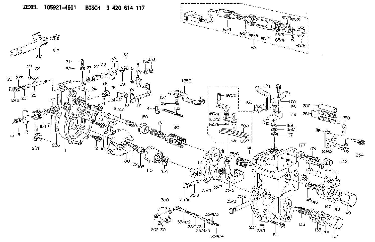
BOSCH
9 420 614 117
9420614117
ZEXEL
105921-4601
1059214601
Rating:
Scheme ###:
| 1. | [1] | 159200-5620 | GOVERNOR HOUSING |
| 1/3. | [1] | 154321-0400 | BUSHING |
| 2. | [8] | 020106-2040 | BLEEDER SCREW M6P1L20 |
| 2. | [8] | 020106-2040 | BLEEDER SCREW M6P1L20 |
| 4. | [1] | 159232-0401 | PLATE |
| 7. | [1] | 016530-1010 | O-RING |
| 8. | [1] | 159205-5720 | LEVER SHAFT |
| 9. | [1] | 159202-2601 | CONTROL LEVER |
| 10. | [1] | 016010-0810 | LOCKING WASHER |
| 11/1. | [0] | 029311-0520 | SHIM D20.8&10.3T0.2 |
| 11/1. | [0] | 029311-0530 | SHIM D20.8&10.3T0.25 |
| 11/1. | [0] | 029311-0540 | SHIM D20.8&10.3T0.3 |
| 11/1. | [0] | 029311-0550 | SHIM D20.8&10.3T0.35 |
| 11/1. | [0] | 029311-0560 | SHIM D20.8&10.3T0.4 |
| 11/1. | [0] | 029311-0570 | SHIM D20.8&10.3T0.5 |
| 12. | [1] | 159215-0500 | COILED SPRING |
| 13. | [1] | 159242-9100 | CONTROL LEVER |
| 14. | [1] | 014110-8440 | LOCKING WASHER |
| 15. | [1] | 013020-8040 | UNION NUT M8P1.25H7 |
| 16. | [1] | 159237-0601 | CAPSULE |
| 17. | [1] | 159202-2720 | CONTROL LEVER |
| 18. | [1] | 159215-0600 | COILED SPRING |
| 20. | [1] | 155004-4700 | LEVER SHAFT |
| 21. | [2] | 020104-1240 | BLEEDER SCREW |
| 22. | [1] | 159244-6100 | CONTROL LEVER |
| 23. | [2] | 029620-8050 | PACKING RING |
| 23. | [2] | 029620-8050 | PACKING RING |
| 24. | [0] | 029300-8010 | PLAIN WASHER D15&8T1.00 |
| 24B. | [0] | 029300-8030 | PLAIN WASHER D15&8T1.50 |
| 25. | [1] | 025520-1210 | SPLIT PIN |
| 26. | [1] | 154206-2000 | BUSHING |
| 27. | [1] | 154327-4200 | COILED SPRING |
| 27B. | [1] | 154327-4200 | COILED SPRING |
| 28. | [1] | 159249-6600 | CONTROL LEVER |
| 29. | [1] | 014110-8440 | LOCKING WASHER |
| 30. | [1] | 013020-8040 | UNION NUT M8P1.25H7 |
| 31. | [1] | 153141-1800 | SET OF NUTS |
| 32. | [1] | 013030-6040 | UNION NUT M6P1H3.6 |
| 35. | [1] | 159250-2220 | GOVERNOR COVER |
| 35/1. | [1] | 159201-4720 | GOVERNOR COVER |
| 35/2. | [1] | 159205-0400 | LEVER SHAFT |
| 35/3. | [2] | 159226-0100 | CAPSULE |
| 35/4. | [1] | 159203-5920 | TENSIONING LEVER |
| 35/4/2. | [1] | 159204-5021 | RACK |
| 35/4/3. | [1] | 159233-0300 | UNION NUT |
| 35/4/4. | [1] | 159234-0300 | FLAT-HEAD SCREW |
| 35/4/5. | [1] | 159216-0000 | COILED SPRING |
| 35/4/6. | [1] | 159216-0100 | COILED SPRING |
| 35/5. | [1] | 159203-5420 | GUIDE LEVER |
| 35/6. | [2] | 159235-5000 | BUSHING |
| 35/7. | [1] | 159215-5100 | COILED SPRING |
| 35/8. | [1] | 159231-1300 | BEARING PIN |
| 35/9. | [2] | 016010-0610 | LOCKING WASHER |
| 51. | [6] | 020106-3840 | BLEEDER SCREW |
| 65. | [1] | 154610-3720 | RACK SENSOR ASSY |
| 65/1. | [1] | 479743-9520 | RACK SENSOR ASSY |
| 65/2. | [1] | 154614-5100 | JOINT CONNECTION |
| 65/3. | [1] | 154614-3100 | BLOCK |
| 65/4. | [1] | 010234-1040 | HEX-SOCKET-HEAD CAP SCREW |
| 65/5. | [1] | 014110-4440 | LOCKING WASHER |
| 65/6. | [1] | 026524-3040 | GASKET |
| 65/7A. | [0] | 029310-6220 | SHIM D11.5&6.5T0.10 |
| 65/7B. | [0] | 029310-6230 | SHIM D11.5&6.5T0.20 |
| 65/7C. | [0] | 029310-6240 | SHIM D11.5&6.5T0.25 |
| 65/7D. | [0] | 029310-6260 | SHIM D11.5&6.4T1.00 |
| 65/7E. | [0] | 029310-6270 | SHIM D11.5&6.4T1.20 |
| 65/7F. | [0] | 029310-6280 | SHIM D11.5&6.4T1.50 |
| 65/8. | [1] | 154614-1900 | UNION NUT |
| 65/9. | [1] | 154614-3300 | BEARING PIN |
| 100. | [1] | 154100-9320 | FLYWEIGHT ASSEMBLY |
| 101. | [1] | 025803-1310 | WOODRUFF KEY |
| 102. | [1] | 029321-2020 | LOCKING WASHER |
| 103. | [1] | 029231-2030 | UNION NUT |
| 110. | [1] | 154123-2320 | SLIDING PIECE |
| 111/1. | [0] | 029311-0010 | SHIM D14&10.1T0.2 |
| 111/1. | [0] | 029311-0180 | SHIM D14&10.1T0.3 |
| 111/1. | [0] | 029311-0190 | SHIM D14&10.1T0.40 |
| 111/1. | [0] | 029311-0210 | SHIM D14&10.1T1 |
| 111/1. | [0] | 139410-0000 | SHIM D14.0&10.1T0.5 |
| 111/1. | [0] | 139410-0100 | SHIM D14.0&10.1T1.5 |
| 111/1. | [0] | 139410-3000 | SHIM D14&10.1T2.0 |
| 111/1. | [0] | 139410-3100 | SHIM D14&10.1T3.0 |
| 111/1. | [0] | 139410-3200 | SHIM D14&10.1T4.0 |
| 112. | [1] | 159236-0100 | TERMINAL STUD |
| 130. | [1] | 159210-5000 | GOVERNOR SPRING |
| 131. | [1] | 159211-5400 | GOVERNOR SPRING |
| 132. | [1] | 159214-0000 | COILED SPRING |
| 133. | [1] | 159219-0320 | HEADLESS SCREW |
| 135. | [1] | 139220-0200 | UNION NUT |
| 136. | [2] | 026520-2440 | GASKET D23.9&20.2T1 |
| 137. | [1] | 159248-0700 | CAP |
| 140. | [1] | 159205-2600 | LEVER SHAFT |
| 141. | [1] | 159234-5200 | GUIDE SLEEVE |
| 145. | [1] | 159233-5000 | UNION NUT |
| 146. | [1] | 023020-8040 | UNION NUT M8P1H5 |
| 147. | [1] | 139222-0200 | UNION NUT |
| 148. | [2] | 026522-2740 | GASKET D26.9&22.2T1 |
| 149. | [1] | 159237-5000 | CAP |
| 150. | [1] | 159235-5300 | SLOTTED WASHER |
| 152. | [1] | 159235-5200 | BUSHING |
| 153. | [2] | 016010-0540 | LOCKING WASHER |
| 155D. | [1] | 159204-5520 | STRAP L52 |
| 156. | [1] | 010235-1020 | HEX-SOCKET-HEAD CAP SCREW |
| 157. | [1] | 029320-5020 | LOCKING WASHER |
| 160. | [1] | 159252-1020 | LEVER GROUP |
| 160/1. | [1] | 159202-1400 | CONTROL LEVER |
| 160/2. | [1] | 159202-1520 | CONTROL LEVER |
| 160/3. | [1] | 016010-0610 | LOCKING WASHER |
| 160/4. | [1] | 159215-2500 | COILED SPRING |
| 160/5. | [1] | 159252-1010 | CONTROL LEVER |
| 160/6. | [1] | 016010-0810 | LOCKING WASHER |
| 164. | [1] | 159244-1000 | CONTROL LEVER |
| 166. | [1] | 020006-1670 | BLEEDER SCREW M6P1L16 7T |
| 166. | [1] | 020006-1670 | BLEEDER SCREW M6P1L16 7T |
| 167. | [1] | 029621-0080 | PACKING RING |
| 168/1. | [0] | 029311-0640 | SHIM D26.0&10.2T0.95 |
| 168/1. | [0] | 029311-0650 | SHIM D26.0&10.2T0.20 |
| 168/1. | [0] | 029311-0660 | SHIM D26.0&10.2T0.25 |
| 168/1. | [0] | 029311-0670 | SHIM D26.0&10.2T0.30 |
| 168/1. | [0] | 029311-0680 | SHIM D26.0&10.2T0.35 |
| 168/1. | [0] | 029311-0690 | SHIM D26.0&10.2T0.40 |
| 168/1. | [0] | 029311-0700 | SHIM D26.0&10.2T0.50 |
| 168/1. | [0] | 139410-1400 | SHIM D26&10.2T0.7 |
| 168/1. | [0] | 139410-1500 | SHIM D26&10.2T0.9 |
| 168/1. | [0] | 139410-1600 | SHIM D26&10.2T0.8 |
| 168/1. | [0] | 139410-2700 | SHIM D26&10.2T0.6 |
| 169. | [1] | 139410-2300 | SHIM |
| 170. | [1] | 159260-8820 | CONTROL LEVER |
| 171. | [2] | 020006-1240 | BLEEDER SCREW M6P1L12 4T |
| 173. | [1] | 154010-5000 | BLEEDER SCREW M8P1.25L30 |
| 173B. | [1] | 154012-4100 | BLEEDER SCREW M8P1.25L32.5 |
| 173C. | [1] | 154013-0800 | BLEEDER SCREW M8P1.25L35 |
| 174. | [1] | 154010-6000 | BLEEDER SCREW M10P1.25L55 |
| 174C. | [1] | 154010-5600 | BLEEDER SCREW M10P1.25L60 |
| 175. | [1] | 154010-5500 | BLEEDER SCREW M10P1.25L42 |
| 176. | [1] | 159226-0900 | UNION NUT |
| 177. | [1] | 154011-2200 | UNION NUT |
| 178. | [1] | 154011-2100 | UNION NUT |
| 235. | [1] | 155412-5200 | IMPELLER WHEEL |
| 235B. | [1] | 155412-5300 | IMPELLER WHEEL |
| 236. | [1] | 159238-5100 | GASKET |
| 237. | [1] | 159238-2200 | GASKET |
| 250. | [1] | 159226-0320 | BRACKET |
| 251. | [2] | 159243-1200 | COILED SPRING |
| 252. | [2] | 020106-1040 | BLEEDER SCREW M6P1L12 |
| 254. | [1] | 020018-1640 | BLEEDER SCREW M8P1.25L16 4T |
| 257. | [2] | 154156-1800 | TUBE |
| 300. | [1] | 159283-0700 | CAM PLATE |
| 301. | [1] | 016010-0840 | LOCKING WASHER |
| 303. | [1] | 016010-0540 | LOCKING WASHER |
| 310. | [1] | 026516-2040 | GASKET D19.9&16.2T1 |
| 311. | [1] | 159237-0100 | CAPSULE |
| 312. | [1] | 159228-0300 | BRACKET |
| 313. | [2] | 010010-1240 | BLEEDER SCREW M10P1.5L12 4T |
| 835S. | [1] | 154062-1900 | CAP D12L24 |
| 836S. | [1] | 154062-1700 | CAP D20L32 |
| 900S. | [1] | 025803-1310 | WOODRUFF KEY |
| 901S. | [1] | 025803-1610 | WOODRUFF KEY |
Include in #1:
106871-8611
as GOVERNOR
Cross reference number
Zexel num
Bosch num
Firm num
Name
Information:
Introduction
The problem that is identified below does not have a known permanent solution. Until a permanent solution is known, use the solution that is identified below.Problem
Some of the 3408E engines and 3412E engines in the above listed machines may experience hard starting or low power due to oil that is leaking past the poppet valve in the injector. The oil leakage is caused by the operating conditions at either low idle or high idle. Excessive oil leakage can reduce actuation pressure to the fuel injector. This may prevent fuel injection.Solution
Electrical shock hazard. The electronic unit injector system uses 90-120 volts.
Follow the proper troubleshooting procedure for the correct engine. If the problem is not located and the symptoms that are listed above continue, remove the engine valve covers. Electrically disable the injectors. Crank the engine. Watch the spill ports of the injector for oil leakage. A small amount of oil leakage is acceptable. A continuous stream of oil may mean leakage from the poppet valve. Excessive leakage from the poppet valve may prevent fuel injection.Note: Normal oil pressure during cranking should be 5 MPa (725 psi). Oil pressure below 5 MPa (725 psi) may indicate excessive oil leakage in injectors. Do not replace the oil pump. Service personnel should replace the injectors that have a continuous flow of oil from the oil ports. Injectors that have a continuous flow of oil and injectors that are within the guidelines of warranty can be returned. Injectors that do not have a continuous flow of oil should not be replaced. Injectors that do not have a continuous flow of oil should not be returned.Note: For additional information on the operation of Hydraulic Electronic Unit Injectors HEUI, refer to CD, RENR1390.
Illustration 1 g01308874
(1) Oil drain portThe oil drain ports are located underneath the solenoid. This will direct the oil flow downward. Some oil may also leak from the rectangular slots at the side of the solenoid. Excess oil leakage will still be visible on the cylinder head.