Information governor
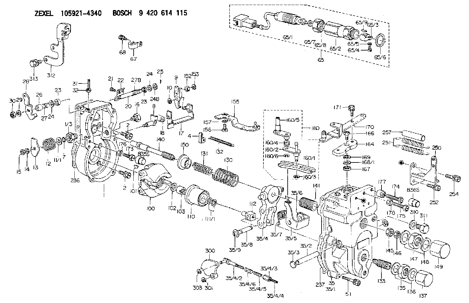
BOSCH
9 420 614 115
9420614115
ZEXEL
105921-4340
1059214340
HINO
223005470A
223005470a
Rating:
Scheme ###:
| 1. | [1] | 159200-2920 | GOVERNOR HOUSING |
| 1/3. | [1] | 154321-0400 | BUSHING |
| 2. | [8] | 020106-2040 | BLEEDER SCREW M6P1L20 |
| 2. | [8] | 020106-2040 | BLEEDER SCREW M6P1L20 |
| 4. | [1] | 159232-0401 | PLATE |
| 7. | [1] | 016530-1010 | O-RING |
| 8. | [1] | 159205-2821 | LEVER SHAFT |
| 9. | [1] | 159202-2601 | CONTROL LEVER |
| 10. | [1] | 016010-0810 | LOCKING WASHER |
| 11/1. | [0] | 029311-0520 | SHIM D20.8&10.3T0.2 |
| 11/1. | [0] | 029311-0530 | SHIM D20.8&10.3T0.25 |
| 11/1. | [0] | 029311-0540 | SHIM D20.8&10.3T0.3 |
| 11/1. | [0] | 029311-0550 | SHIM D20.8&10.3T0.35 |
| 11/1. | [0] | 029311-0560 | SHIM D20.8&10.3T0.4 |
| 11/1. | [0] | 029311-0570 | SHIM D20.8&10.3T0.5 |
| 12. | [1] | 159215-0500 | COILED SPRING |
| 13. | [1] | 159242-9100 | CONTROL LEVER |
| 14. | [1] | 014110-8440 | LOCKING WASHER |
| 15. | [1] | 013020-8040 | UNION NUT M8P1.25H7 |
| 16. | [1] | 159237-0600 | CAPSULE |
| 17. | [1] | 159202-2720 | CONTROL LEVER |
| 18. | [1] | 159215-0600 | COILED SPRING |
| 20. | [1] | 155004-4700 | LEVER SHAFT |
| 21. | [2] | 020104-1240 | BLEEDER SCREW |
| 22. | [1] | 159244-6100 | CONTROL LEVER |
| 23. | [2] | 029620-8050 | PACKING RING |
| 23. | [2] | 029620-8050 | PACKING RING |
| 24. | [0] | 029300-8010 | PLAIN WASHER D15&8T1.00 |
| 24. | [0] | 029300-8010 | PLAIN WASHER D15&8T1.00 |
| 24B. | [0] | 029300-8030 | PLAIN WASHER D15&8T1.50 |
| 25. | [1] | 025520-1210 | SPLIT PIN |
| 26. | [1] | 154206-2000 | BUSHING |
| 27. | [1] | 154327-3600 | COILED SPRING |
| 27B. | [1] | 154327-4200 | COILED SPRING |
| 28. | [1] | 159249-1000 | CONTROL LEVER |
| 29. | [1] | 014110-8440 | LOCKING WASHER |
| 30. | [1] | 013020-8040 | UNION NUT M8P1.25H7 |
| 31. | [1] | 154404-1800 | FLAT-HEAD SCREW L34.00 |
| 32. | [1] | 013030-6040 | UNION NUT M6P1H3.6 |
| 35. | [1] | 159251-5320 | GOVERNOR COVER |
| 35/1. | [1] | 159201-4720 | GOVERNOR COVER |
| 35/2. | [1] | 159205-0400 | LEVER SHAFT |
| 35/3. | [2] | 159226-0100 | CAPSULE |
| 35/4. | [1] | 159203-5920 | TENSIONING LEVER |
| 35/4/2. | [1] | 159204-5021 | RACK |
| 35/4/3. | [1] | 159233-0300 | UNION NUT |
| 35/4/4. | [1] | 159234-0300 | FLAT-HEAD SCREW |
| 35/4/5. | [1] | 159216-0000 | COILED SPRING |
| 35/4/6. | [1] | 159216-0100 | COILED SPRING |
| 35/5. | [1] | 159203-5420 | GUIDE LEVER |
| 35/6. | [2] | 159235-5000 | BUSHING |
| 35/7. | [1] | 159215-5100 | COILED SPRING |
| 35/8. | [1] | 159231-1300 | BEARING PIN |
| 35/9. | [2] | 016010-0610 | LOCKING WASHER |
| 51. | [6] | 020106-3840 | BLEEDER SCREW |
| 65. | [1] | 154610-3420 | RACK SENSOR ASSY |
| 65/1. | [1] | 479743-9520 | RACK SENSOR ASSY |
| 65/2. | [1] | 154614-2300 | JOINT CONNECTION |
| 65/3. | [1] | 154614-3100 | BLOCK |
| 65/4. | [1] | 010234-1040 | HEX-SOCKET-HEAD CAP SCREW |
| 65/5. | [1] | 014110-4440 | LOCKING WASHER |
| 65/6. | [1] | 026524-3040 | GASKET |
| 65/7A. | [0] | 029310-6220 | SHIM D11.5&6.5T0.10 |
| 65/7B. | [0] | 029310-6230 | SHIM D11.5&6.5T0.20 |
| 65/7C. | [0] | 029310-6240 | SHIM D11.5&6.5T0.25 |
| 65/7D. | [0] | 029310-6260 | SHIM D11.5&6.4T1.00 |
| 65/7E. | [0] | 029310-6270 | SHIM D11.5&6.4T1.20 |
| 65/7F. | [0] | 029310-6280 | SHIM D11.5&6.4T1.50 |
| 65/8. | [1] | 154614-1900 | UNION NUT |
| 65/9. | [1] | 154614-3300 | BEARING PIN |
| 67. | [1] | 159564-4400 | CLAMPING BAND |
| 68. | [1] | 020106-1240 | BLEEDER SCREW M6P1.0L12 |
| 100. | [1] | 154100-9520 | FLYWEIGHT ASSEMBLY |
| 101. | [1] | 025803-1610 | WOODRUFF KEY |
| 102. | [1] | 029321-2020 | LOCKING WASHER |
| 103. | [1] | 029231-2030 | UNION NUT |
| 110. | [1] | 154123-2320 | SLIDING PIECE |
| 111/1. | [0] | 029311-0010 | SHIM D14&10.1T0.2 |
| 111/1. | [0] | 029311-0180 | SHIM D14&10.1T0.3 |
| 111/1. | [0] | 029311-0190 | SHIM D14&10.1T0.40 |
| 111/1. | [0] | 029311-0210 | SHIM D14&10.1T1 |
| 111/1. | [0] | 139410-0000 | SHIM D14.0&10.1T0.5 |
| 111/1. | [0] | 139410-0100 | SHIM D14.0&10.1T1.5 |
| 111/1. | [0] | 139410-3000 | SHIM D14&10.1T2.0 |
| 111/1. | [0] | 139410-3100 | SHIM D14&10.1T3.0 |
| 111/1. | [0] | 139410-3200 | SHIM D14&10.1T4.0 |
| 112. | [1] | 159236-0100 | TERMINAL STUD |
| 130. | [1] | 159210-6900 | GOVERNOR SPRING |
| 131. | [1] | 159211-4600 | GOVERNOR SPRING |
| 132. | [1] | 159214-0000 | COILED SPRING |
| 133. | [1] | 159212-8420 | HEADLESS SCREW |
| 135. | [1] | 139220-0200 | UNION NUT |
| 136. | [2] | 026520-2440 | GASKET D23.9&20.2T1 |
| 137. | [1] | 159248-0700 | CAP |
| 140. | [1] | 159205-2600 | LEVER SHAFT |
| 141. | [1] | 159234-5200 | GUIDE SLEEVE |
| 145. | [1] | 159233-5000 | UNION NUT |
| 146. | [1] | 023020-8040 | UNION NUT M8P1H5 |
| 147. | [1] | 139222-0200 | UNION NUT |
| 148. | [2] | 026522-2740 | GASKET D26.9&22.2T1 |
| 149. | [1] | 159237-5000 | CAP |
| 150. | [1] | 159235-5300 | SLOTTED WASHER |
| 152. | [1] | 159235-5200 | BUSHING |
| 153. | [2] | 016010-0540 | LOCKING WASHER |
| 155. | [1] | 159204-5520 | STRAP L52 |
| 156. | [1] | 010535-1040 | FLAT-HEAD SCREW M5P0.8L10 |
| 157. | [1] | 029320-5020 | LOCKING WASHER |
| 160. | [1] | 159252-1020 | LEVER GROUP |
| 160/1. | [1] | 159202-1400 | CONTROL LEVER |
| 160/2. | [1] | 159202-1520 | CONTROL LEVER |
| 160/3. | [1] | 016010-0610 | LOCKING WASHER |
| 160/4. | [1] | 159215-2500 | COILED SPRING |
| 160/5. | [1] | 159252-1010 | CONTROL LEVER |
| 160/6. | [1] | 016010-0810 | LOCKING WASHER |
| 164. | [1] | 159244-1000 | CONTROL LEVER |
| 166. | [1] | 020006-1670 | BLEEDER SCREW M6P1L16 7T |
| 167. | [1] | 029621-0080 | PACKING RING |
| 168/1. | [0] | 029311-0640 | SHIM D26.0&10.2T0.95 |
| 168/1. | [0] | 029311-0650 | SHIM D26.0&10.2T0.20 |
| 168/1. | [0] | 029311-0660 | SHIM D26.0&10.2T0.25 |
| 168/1. | [0] | 029311-0670 | SHIM D26.0&10.2T0.30 |
| 168/1. | [0] | 029311-0680 | SHIM D26.0&10.2T0.35 |
| 168/1. | [0] | 029311-0690 | SHIM D26.0&10.2T0.40 |
| 168/1. | [0] | 029311-0700 | SHIM D26.0&10.2T0.50 |
| 168/1. | [0] | 139410-1400 | SHIM D26&10.2T0.7 |
| 168/1. | [0] | 139410-1500 | SHIM D26&10.2T0.9 |
| 168/1. | [0] | 139410-1600 | SHIM D26&10.2T0.8 |
| 168/1. | [0] | 139410-2700 | SHIM D26&10.2T0.6 |
| 169. | [1] | 139410-2300 | SHIM |
| 170. | [1] | 159244-7720 | CONTROL LEVER |
| 171. | [2] | 020006-1240 | BLEEDER SCREW M6P1L12 4T |
| 173. | [1] | 154010-5000 | BLEEDER SCREW M8P1.25L30 |
| 173B. | [1] | 154012-4100 | BLEEDER SCREW M8P1.25L32.5 |
| 173C. | [1] | 154013-0800 | BLEEDER SCREW M8P1.25L35 |
| 174. | [1] | 154010-6000 | BLEEDER SCREW M10P1.25L55 |
| 174C. | [1] | 154010-5600 | BLEEDER SCREW M10P1.25L60 |
| 175. | [1] | 154010-5500 | BLEEDER SCREW M10P1.25L42 |
| 176. | [1] | 159226-0900 | UNION NUT |
| 177. | [1] | 154011-2200 | UNION NUT |
| 178. | [1] | 154011-2100 | UNION NUT |
| 236. | [1] | 154371-5600 | GASKET |
| 237. | [1] | 159238-2200 | GASKET |
| 250. | [1] | 159226-0320 | BRACKET |
| 251. | [2] | 159243-1200 | COILED SPRING |
| 252. | [2] | 020106-1040 | BLEEDER SCREW M6P1L12 |
| 254. | [1] | 020018-1640 | BLEEDER SCREW M8P1.25L16 4T |
| 257. | [2] | 154156-1800 | TUBE |
| 300. | [1] | 159282-2600 | CAM PLATE |
| 301. | [1] | 016010-0840 | LOCKING WASHER |
| 303. | [1] | 016010-0540 | LOCKING WASHER |
| 310. | [1] | 026516-2040 | GASKET D19.9&16.2T1 |
| 311. | [1] | 159237-0100 | CAPSULE |
| 312. | [1] | 159226-6900 | BRACKET |
| 313. | [2] | 010010-1240 | BLEEDER SCREW M10P1.5L12 4T |
| 835S. | [1] | 154062-1900 | CAP D12L24 |
| 836S. | [1] | 154062-1700 | CAP D20L32 |
Include in #1:
106671-8390
as GOVERNOR
Cross reference number
Zexel num
Bosch num
Firm num
Name
Information:
Rework Procedure
This procedure is only required when utilizing the 444-2472 Bracket As or 444-2473 Bracket As, the former 222-6953 Valve Cover Bases, and the new stamped steel valve covers. Disregard if using 442-5727 Valve Cover Base.The preferred method to correct this issue is to remove the former 222-6953 Valve Cover Base and install the current 442-5727 Valve Cover Base. This valve cover base removes the need for the 444-2472 Bracket As and 444-2473 Bracket As.The alternative method is to modify the 444-2472 Bracket As or 444-2473 Bracket As to be used with the 222-6953 Valve Mechanism Cover Base and stamped steel valve cover.Note:
Illustration 1 g06088172
Bracket assemblies view
(1) 444-2472 Bracket As
(2) 444-2473 Bracket As
Illustration 2 g06088191
Side view of the bracket.
(3) Button portion
(4) Weld stud
Illustration 3 g06088192
Top view of the bracket.
The illustration above shows the location of the material that will need to be removed from the button of the bracket assemblies.
Illustration 4 g06088194
Side view of the bracket.
Illustration 5 g06088195
View of the bracket after modification.
Remove 4 mm (0.16 in) from the button on the bracket as shown in Illustration 4.
Once the additional material has been removed from the modified bracket, fit the valve cover to ensure that proper clearance has been created allowing sealing of valve cover PIP seal. Install and torque the valve cover using the appropriate procedure from the Disassembly and Assembly manual.
Illustration 6 g06088196
Impression made by bracket assemblies that contact the valve cover.
Remove the valve cover and inspect the mating surface to see if any contact marks are present as shown in Illustration 6. If contact marks are present, extra material of the button will need to be removed for clearance.