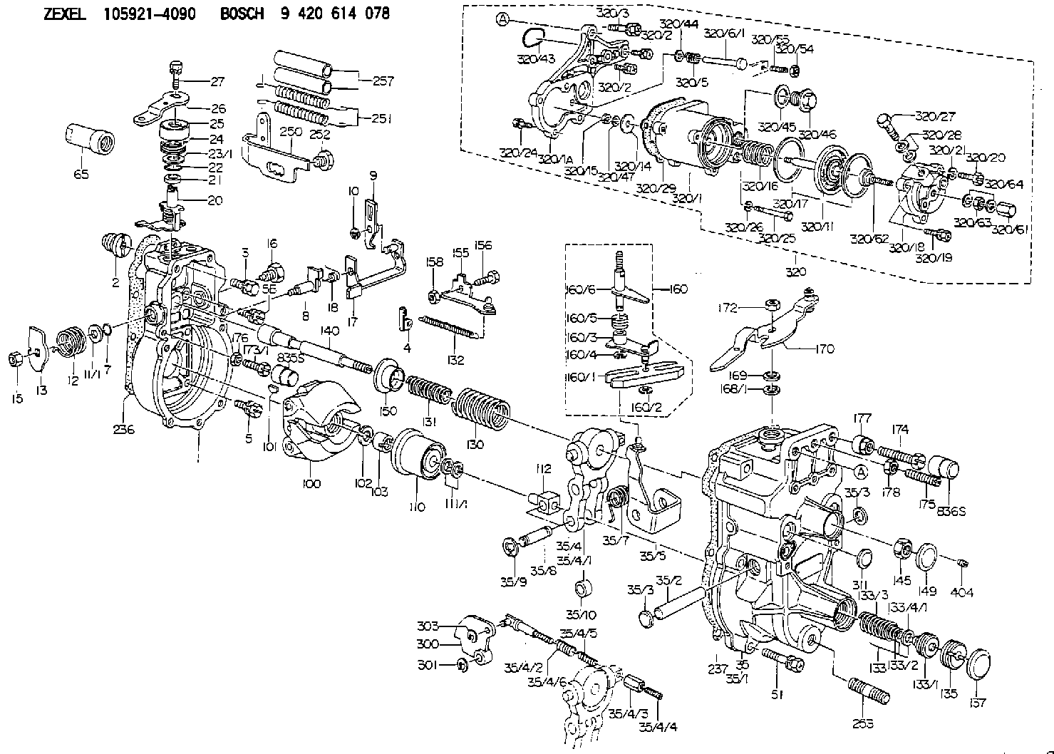
Information governor
BOSCH
9 420 614 078
9420614078
ZEXEL
105921-4090
1059214090
Rating:
Scheme ###:
| 1. | [1] | 159200-4520 | GOVERNOR HOUSING |
| 2. | [1] | 154007-0200 | ADAPTOR |
| 3. | [1] | 020018-1840 | BLEEDER SCREW M8P1.25L18 |
| 4. | [1] | 159232-2720 | PLATE |
| 5. | [5] | 029010-6810 | BLEEDER SCREW |
| 5B. | [1] | 020106-1640 | BLEEDER SCREW M6P1.0L14 |
| 7. | [1] | 029631-0050 | O-RING |
| 8. | [1] | 159205-2821 | LEVER SHAFT |
| 9. | [1] | 159202-4101 | CONTROL LEVER |
| 10. | [1] | 016010-0810 | LOCKING WASHER |
| 11/1. | [0] | 029311-0220 | SHIM D18&10.3T0.2 |
| 11/1. | [0] | 029311-0230 | SHIM D18&10.3T0.5 |
| 11/1. | [0] | 029311-0430 | SHIM D18&10.3T0.30 |
| 11/1. | [0] | 029311-0440 | SHIM D18&10.3T0.40 |
| 11/1. | [0] | 029311-0450 | SHIM D18&10.3T0.25 |
| 11/1. | [0] | 029311-0460 | SHIM D18&10.3T0.35 |
| 11/1. | [0] | 139410-3300 | SHIM D18&10.3T0.6 |
| 11/1. | [0] | 139410-3400 | SHIM D18&10.3T0.8 |
| 11/1. | [0] | 139410-3500 | SHIM D18&10.3T0.9 |
| 12. | [1] | 159215-0500 | COILED SPRING |
| 13. | [1] | 159242-6601 | CONTROL LEVER |
| 15. | [1] | 013020-8040 | UNION NUT M8P1.25H7 |
| 16. | [1] | 159237-5500 | CAPSULE |
| 17. | [1] | 159202-5520 | CONTROL LEVER |
| 18. | [1] | 159215-0600 | COILED SPRING |
| 20. | [1] | 159242-0920 | CONTROL LEVER |
| 21. | [1] | 159242-0600 | BUSHING |
| 22. | [1] | 029631-0050 | O-RING |
| 23/1. | [0] | 139410-1300 | SHIM D20.8&10.2T0.3 |
| 23/1. | [0] | 139410-1700 | SHIM D20.8&10.2T0.2 |
| 23/1. | [0] | 139410-1800 | SHIM D20.8&10.2T0.4 |
| 23/1. | [0] | 139410-2800 | SHIM D20.8&10.2T0.6 |
| 23/1. | [0] | 139410-3700 | SHIM D20.8&10.2T0.9 |
| 24. | [1] | 159215-3100 | COILED SPRING |
| 25. | [1] | 159235-5800 | CAP |
| 26. | [1] | 159290-2300 | CONTROL LEVER |
| 27. | [1] | 020006-1640 | BLEEDER SCREW M6P1L16 4T |
| 35. | [1] | 159250-2420 | GOVERNOR COVER |
| 35/1. | [1] | 159201-7420 | GOVERNOR COVER |
| 35/2. | [1] | 159205-0400 | LEVER SHAFT |
| 35/3. | [2] | 159237-0200 | CAPSULE |
| 35/3. | [2] | 159237-0200 | CAPSULE |
| 35/4. | [1] | 159253-1720 | TENSIONING LEVER |
| 35/4/1. | [1] | 159203-1520 | TENSIONING LEVER |
| 35/4/2. | [1] | 159204-5021 | RACK |
| 35/4/3. | [1] | 159233-0300 | UNION NUT |
| 35/4/4. | [1] | 159234-0300 | FLAT-HEAD SCREW |
| 35/4/5. | [1] | 159216-0000 | COILED SPRING |
| 35/4/6. | [1] | 159216-0100 | COILED SPRING |
| 35/5. | [1] | 159203-6220 | GUIDE LEVER |
| 35/7. | [1] | 159215-4101 | COILED SPRING |
| 35/8. | [1] | 159231-1300 | BEARING PIN |
| 35/9. | [2] | 016010-0610 | LOCKING WASHER |
| 35/10. | [1] | 159238-2900 | BUSHING |
| 51. | [7] | 020106-3840 | BLEEDER SCREW |
| 65. | [1] | 154050-8820 | STOPPING DEVICE |
| 100. | [1] | 154100-9520 | FLYWEIGHT ASSEMBLY |
| 101. | [1] | 025803-1610 | WOODRUFF KEY |
| 102. | [1] | 029321-2020 | LOCKING WASHER |
| 103. | [1] | 029231-2030 | UNION NUT |
| 110. | [1] | 154123-2720 | SLIDING PIECE |
| 111/1. | [0] | 029311-0010 | SHIM D14&10.1T0.2 |
| 111/1. | [0] | 029311-0180 | SHIM D14&10.1T0.3 |
| 111/1. | [0] | 029311-0190 | SHIM D14&10.1T0.40 |
| 111/1. | [0] | 029311-0210 | SHIM D14&10.1T1 |
| 111/1. | [0] | 139410-0000 | SHIM D14.0&10.1T0.5 |
| 111/1. | [0] | 139410-0100 | SHIM D14.0&10.1T1.5 |
| 111/1. | [0] | 139410-3000 | SHIM D14&10.1T2.0 |
| 111/1. | [0] | 139410-3100 | SHIM D14&10.1T3.0 |
| 111/1. | [0] | 139410-3200 | SHIM D14&10.1T4.0 |
| 112. | [1] | 159236-0200 | TERMINAL STUD |
| 130. | [1] | 159210-6300 | GOVERNOR SPRING |
| 131. | [1] | 159211-3000 | GOVERNOR SPRING |
| 132. | [1] | 159214-0000 | COILED SPRING |
| 133. | [1] | 159212-7020 | SPRING PACK |
| 133/1. | [1] | 159234-5602 | GUIDE SLEEVE |
| 133/2. | [1] | 159212-4700 | COILED SPRING |
| 133/3. | [1] | 159212-6401 | COILED SPRING |
| 133/4/1. | [0] | 029310-9240 | SHIM D11.9&9T0.1 |
| 133/4/1. | [0] | 029310-9250 | SHIM D11.9&9T0.2 |
| 133/4/1. | [0] | 029310-9260 | SHIM D11.9&9T0.25 |
| 133/4/1. | [0] | 029310-9270 | SHIM D11.9&9T1.0 |
| 133/4/1. | [0] | 139409-0100 | SHIM D11.9&9T0.3 |
| 133/4/1. | [0] | 139409-0200 | SHIM D11.9&9T0.5 |
| 133/4/1. | [0] | 139409-0300 | SHIM D11.5&9T0.8 |
| 135. | [1] | 159248-2700 | FLAT-HEAD SCREW |
| 137. | [1] | 159237-5300 | CAPSULE |
| 140. | [1] | 159205-2101 | LEVER SHAFT |
| 145. | [1] | 159233-5700 | UNION NUT |
| 149. | [1] | 159237-5400 | CAPSULE |
| 150. | [1] | 159235-5300 | SLOTTED WASHER |
| 155. | [1] | 159204-7820 | STRAP |
| 156. | [1] | 159233-0520 | BLEEDER SCREW |
| 158. | [1] | 013020-5240 | UNION NUT M5P0.8H4 |
| 160. | [1] | 159252-1121 | LEVER GROUP |
| 160/1. | [1] | 159202-2200 | CONTROL LEVER |
| 160/2. | [1] | 016010-0810 | LOCKING WASHER |
| 160/3. | [1] | 159202-3120 | CONTROL LEVER |
| 160/4. | [1] | 016010-0810 | LOCKING WASHER |
| 160/5. | [1] | 159215-2600 | COILED SPRING |
| 160/6. | [1] | 159205-2922 | LEVER SHAFT |
| 168/1. | [0] | 139410-1200 | SHIM D26&10.2T0.3 |
| 168/1. | [0] | 139410-1900 | SHIM D26&10.2T0.2 |
| 168/1. | [0] | 139410-2000 | SHIM D26&10.2T0.4 |
| 168/1. | [0] | 139410-2400 | SHIM D26&10.2T0.35 |
| 168/1. | [0] | 139410-2500 | SHIM D26&10.2T0.25 |
| 168/1. | [0] | 139410-2900 | SHIM D26&10.2T0.6 |
| 169. | [1] | 139410-2100 | SHIM |
| 170. | [1] | 159262-2720 | CONTROL LEVER |
| 172. | [1] | 013020-8040 | UNION NUT M8P1.25H7 |
| 173/1. | [1] | 139006-3500 | BLEEDER SCREW M6P1.0L33 |
| 173/1. | [1] | 139006-3700 | BLEEDER SCREW M6P1.0L34 |
| 173/1. | [1] | 139006-3800 | BLEEDER SCREW M6P1.0L35 |
| 173/1. | [1] | 139006-3900 | BLEEDER SCREW M6P1.0L36 |
| 173/1. | [1] | 139006-5300 | BLEEDER SCREW M6P1.0L31 |
| 173/1. | [1] | 139006-5400 | BLEEDER SCREW M6P1.0L32 |
| 173/1. | [1] | 155615-2500 | BLEEDER SCREW M6P1.0L37 |
| 174. | [1] | 154010-7200 | BLEEDER SCREW M8P1.25L62 |
| 175. | [1] | 154010-0100 | FLAT-HEAD SCREW |
| 176. | [1] | 159225-8600 | UNION NUT |
| 177. | [1] | 154011-2300 | UNION NUT |
| 178. | [1] | 154011-0100 | HEXAGON NUT |
| 236. | [1] | 154390-1300 | GASKET |
| 237. | [1] | 159238-3100 | GASKET |
| 250. | [1] | 159227-6420 | BRACKET |
| 251. | [2] | 159243-6900 | COILED SPRING |
| 252. | [1] | 159248-0200 | BLEEDER SCREW |
| 253. | [1] | 139010-0000 | STUD |
| 257. | [2] | 154156-0600 | TUBE |
| 300. | [1] | 159280-3600 | CAM PLATE |
| 301. | [1] | 016010-0840 | LOCKING WASHER |
| 303. | [1] | 016010-0540 | LOCKING WASHER |
| 311. | [1] | 159237-0200 | CAPSULE |
| 320. | [1] | 154419-3120 | MANIFOLD-PRESSURE COMP. |
| 320/1. | [1] | 154408-9520 | GOVERNOR HOUSING |
| 320/1A. | [1] | 154412-8600 | SPACER BUSHING |
| 320/2. | [3] | 020106-2240 | BLEEDER SCREW |
| 320/2. | [3] | 020106-2240 | BLEEDER SCREW |
| 320/3. | [1] | 020118-3040 | BLEEDER SCREW |
| 320/5. | [1] | 159275-1400 | COILED SPRING |
| 320/6/1. | [1] | 159274-0120 | STOP PIN L125 |
| 320/6/1. | [1] | 159274-0220 | STOP PIN L127.50 |
| 320/6/1. | [1] | 159274-0320 | STOP PIN L128.00 |
| 320/6/1. | [1] | 159274-0420 | STOP PIN L127.00 |
| 320/6/1. | [1] | 159274-0520 | STOP PIN L126.00 |
| 320/6/1. | [1] | 159274-0620 | STOP PIN L129.00 |
| 320/6/1. | [1] | 159274-0720 | STOP PIN L128.50 |
| 320/6/1. | [1] | 159274-0820 | STOP PIN L125.50 |
| 320/6/1. | [1] | 159274-0920 | STOP PIN L126.50 |
| 320/6/1. | [1] | 159274-1120 | STOP PIN L119.5 |
| 320/6/1. | [1] | 159274-1220 | STOP PIN L120 |
| 320/6/1. | [1] | 159274-1320 | STOP PIN L120.5 |
| 320/6/1. | [1] | 159274-1420 | STOP PIN L121 |
| 320/6/1. | [1] | 159274-1520 | STOP PIN L121.5 |
| 320/6/1. | [1] | 159274-1620 | STOP PIN L122 |
| 320/6/1. | [1] | 159274-1720 | STOP PIN L122.5 |
| 320/6/1. | [1] | 159274-1820 | STOP PIN L123 |
| 320/6/1. | [1] | 159274-1920 | STOP PIN L123.5 |
| 320/6/1. | [1] | 159274-4220 | STOP PIN L129.5 |
| 320/6/1. | [1] | 159274-4320 | STOP PIN L130 |
| 320/6/1. | [1] | 159274-4420 | STOP PIN L130.5 |
| 320/6/1. | [1] | 159274-4520 | STOP PIN L131 |
| 320/6/1. | [1] | 159274-4620 | STOP PIN L131.5 |
| 320/6/1. | [1] | 159274-4720 | STOP PIN L132 |
| 320/6/1. | [1] | 159274-4820 | STOP PIN L132.5 |
| 320/6/1. | [1] | 159274-4920 | STOP PIN L133 |
| 320/6/1. | [1] | 159274-5020 | STOP PIN L133.5 |
| 320/11. | [1] | 154400-8521 | DIAPHRAGM |
| 320/14. | [1] | 154406-5500 | SLOTTED WASHER |
| 320/15. | [1] | 013030-6010 | UNION NUT |
| 320/16. | [1] | 154402-0100 | COILED SPRING |
| 320/17. | [2] | 154413-2600 | GASKET |
| 320/18. | [1] | 154404-5100 | COVER |
| 320/19. | [1] | 020106-2040 | BLEEDER SCREW M6P1L20 |
| 320/20. | [2] | 139006-7000 | BLEEDER SCREW |
| 320/21. | [2] | 014110-6440 | LOCKING WASHER |
| 320/24. | [3] | 020106-2240 | BLEEDER SCREW |
| 320/25. | [1] | 139006-1300 | BLEEDER SCREW M6P1L76 |
| 320/26. | [1] | 029320-6010 | LOCKING WASHER |
| 320/27. | [1] | 029731-0180 | EYE BOLT |
| 320/28. | [2] | 026510-1340 | GASKET D13.4&10.2T1 |
| 320/29. | [1] | 154413-2800 | GASKET |
| 320/43. | [1] | 159226-4500 | SPACER RING |
| 320/44. | [1] | 014010-5140 | PLAIN WASHER D12&5.5T0.8 |
| 320/45. | [1] | 029331-8040 | GASKET |
| 320/46. | [1] | 154406-5800 | FLAT-HEAD SCREW |
| 320/47. | [1] | 014110-6440 | LOCKING WASHER |
| 320/54. | [1] | 013030-6040 | UNION NUT M6P1H3.6 |
| 320/55. | [1] | 154404-4800 | FLAT-HEAD SCREW |
| 320/61. | [1] | 154035-1600 | CAP NUT |
| 320/62. | [1] | 154404-4400 | FLAT-HEAD SCREW |
| 320/63. | [1] | 013030-6040 | UNION NUT M6P1H3.6 |
| 320/64. | [2] | 026506-1040 | GASKET D9.9&6.2T1 |
| 404. | [1] | 011006-0620 | SET OF NUTS |
| 835S. | [1] | 154062-1900 | CAP D12L24 |
| 836S. | [1] | 154062-1700 | CAP D20L32 |
Cross reference number
Zexel num
Bosch num
Firm num
Name
Information:
Introduction
Do not perform any of the following procedure or order parts until you have read and understand the procedure. The procedure that follows below covers that installation of the new Diesel Exhaust Fluid (DEF) filter.Required Parts
Table 1 below contain the parts needed to complete the installation of the new DEF filter.Note: Only one DEF filter group is required per engine. Use Table 2 to determine which filter is the appropriate filter for each DEF header. Illustration 1 shows the location of the DEF header part number.
Table 1
Item Qty Part Number Part Description
1 1 452-6055 Filter Base As
2 1 453-1604(1) Diesel Exhaust Fluid Filter Gp
3 1 453-1605***#i05999309/d1820e940*** Diesel Exhaust Fluid Filter Gp
4 1 453-1606***#i05999309/d1820e940*** Diesel Exhaust Fluid Filter Gp
5 1 378-3187 Diesel Exhaust Fluid Filter Gp
6 1 423-3251 Connector
7 1 425-0385 Filter As
8 1 391-5262 Gasket
(1) Use Table 2 to choose the correct part that corresponds to the DEF header
Illustration 1 g03745839
(1) Location of DEF header part number
Table 2
DEF Header Part Number Required DEF Filter
434-3241 453-1604
434-3242 453-1605
434-3243 453-1606 Installation Procedure
Illustration 2 g03736523
(1) DEF header
(2) DEF filter
(3) DEF tank
(4) DEF header bolts
Clean the area around DEF header (1). Clear any dirt or debris that could contaminate the DEF tank or lines when removed. Note: If proper cleaning is not performed, DEF pump performance issues or failure may occur.
Disconnect the two DEF lines, two coolant lines, and harness from the DEF header assembly.
Remove the six DEF header screws (4) from the DEF header assembly. Note: Do not discard the screws that secure the DEF header assembly to the DEF tank. The screws will be reused in a later step.
Remove the DEF header assembly. Remove the previous DEF header gasket and discard.
Illustration 3 g03736534
(5) 452-6055 Filter Base As
Install filter base assembly (5) onto the DEF header assembly. Note: Each half of the adapter has two small locking tabs that secure to the bottom side of the DEF header assembly.
Remove the previous 425-0385 Filter As located at the bottom of the DEF pick-up tube.
Install the new 425-0385 Filter As onto the DEF header assembly.
Illustration 4 g03736545
(6) Band clamp
Install the correct DEF filter onto the DEF header adapter and secure using band clamp (6) that is supplied. Torque the band clamp to 4.5 0.7 N m (40 6 lb in).
Install the DEF header assembly back into the DEF tank. Secure the DEF header to the DEF tank using the six screws previously removed in Step 3. Torque the six screws to 5 1 N m (44 9 lb in).
Reconnect the harness, coolant lines, and DEF lines to the DEF header.
Illustration 5 g03736566
(7) DEF pump inlet filter fitting
(8) Main DEF pump filter
Replace DEF pump inlet filter fitting (7) and main DEF pump filter (8). Refer to Disassembly and Assembly, UENR0132, "Diesel Exhaust Fluid Filter - Remove and Install" for the replacement procedure.