Information governor
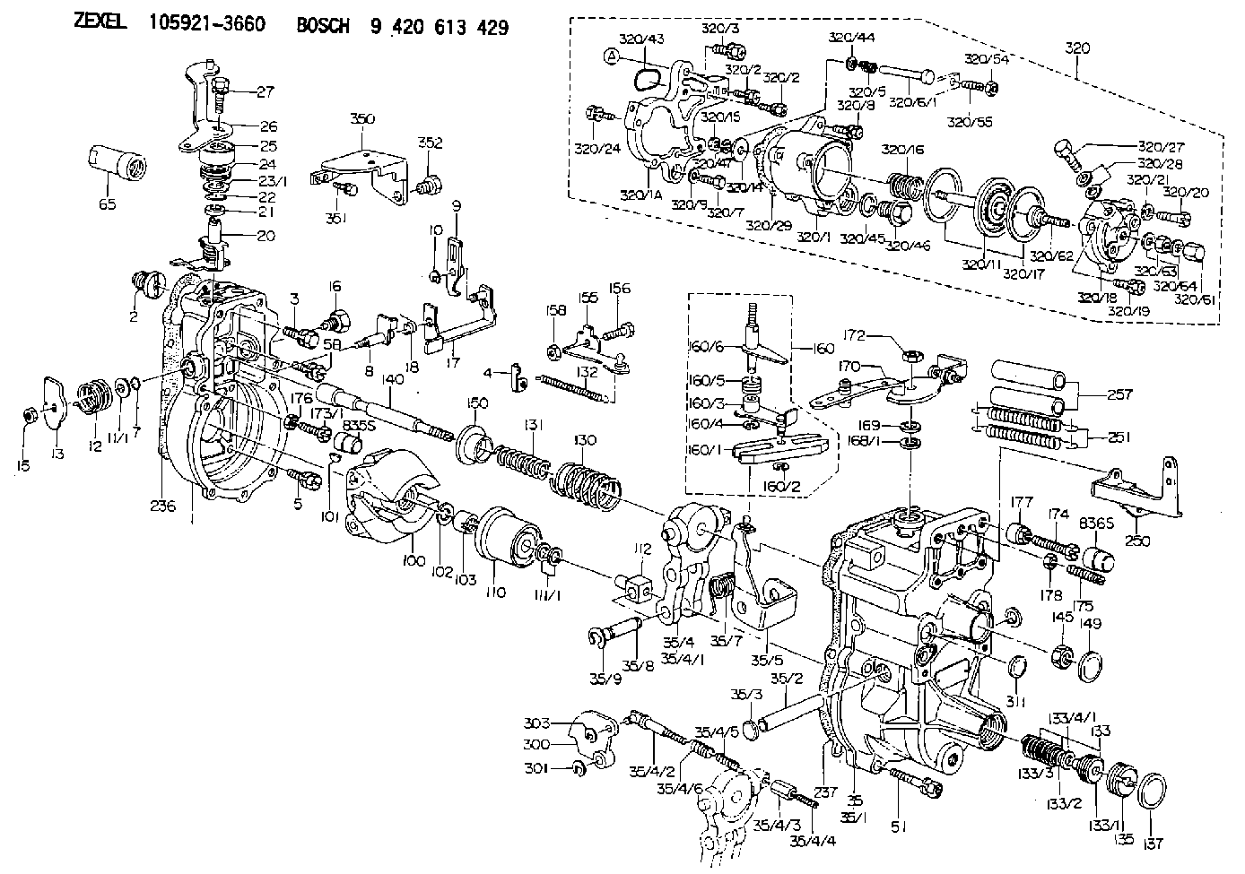
BOSCH
9 420 613 429
9420613429
ZEXEL
105921-3660
1059213660
NISSAN-DIESEL
19101Z5771
19101z5771

Rating:
Scheme ###:
| 1. | [1] | 159200-6320 | GOVERNOR HOUSING |
| 2. | [1] | 154007-0200 | ADAPTOR |
| 3. | [1] | 020018-1840 | BLEEDER SCREW M8P1.25L18 |
| 4. | [1] | 159232-0401 | PLATE |
| 5. | [5] | 029010-6810 | BLEEDER SCREW |
| 5B. | [1] | 020106-1640 | BLEEDER SCREW M6P1.0L14 |
| 7. | [1] | 016530-1010 | O-RING |
| 8. | [1] | 159205-2821 | LEVER SHAFT |
| 9. | [1] | 159202-2900 | CONTROL LEVER |
| 10. | [1] | 016010-0810 | LOCKING WASHER |
| 11/1. | [0] | 029311-0220 | SHIM D18&10.3T0.2 |
| 11/1. | [0] | 029311-0230 | SHIM D18&10.3T0.5 |
| 11/1. | [0] | 029311-0430 | SHIM D18&10.3T0.30 |
| 11/1. | [0] | 029311-0440 | SHIM D18&10.3T0.40 |
| 11/1. | [0] | 029311-0450 | SHIM D18&10.3T0.25 |
| 11/1. | [0] | 029311-0460 | SHIM D18&10.3T0.35 |
| 11/1. | [0] | 139410-3300 | SHIM D18&10.3T0.6 |
| 11/1. | [0] | 139410-3400 | SHIM D18&10.3T0.8 |
| 11/1. | [0] | 139410-3500 | SHIM D18&10.3T0.9 |
| 12. | [1] | 159215-0500 | COILED SPRING |
| 13. | [1] | 159242-6601 | CONTROL LEVER |
| 15. | [1] | 013020-8040 | UNION NUT M8P1.25H7 |
| 16. | [1] | 159237-5200 | CAPSULE |
| 17. | [1] | 159202-3320 | CONTROL LEVER |
| 18. | [1] | 159215-0600 | COILED SPRING |
| 20. | [1] | 159242-0920 | CONTROL LEVER |
| 21. | [1] | 159242-0600 | BUSHING |
| 22. | [1] | 029631-0030 | O-RING &9.8W2.3 |
| 23/1. | [0] | 029311-0220 | SHIM D18&10.3T0.2 |
| 23/1. | [0] | 029311-0230 | SHIM D18&10.3T0.5 |
| 23/1. | [0] | 029311-0430 | SHIM D18&10.3T0.30 |
| 23/1. | [0] | 029311-0440 | SHIM D18&10.3T0.40 |
| 23/1. | [0] | 029311-0450 | SHIM D18&10.3T0.25 |
| 23/1. | [0] | 029311-0460 | SHIM D18&10.3T0.35 |
| 23/1. | [0] | 139410-3300 | SHIM D18&10.3T0.6 |
| 23/1. | [0] | 139410-3400 | SHIM D18&10.3T0.8 |
| 23/1. | [0] | 139410-3500 | SHIM D18&10.3T0.9 |
| 24. | [1] | 159215-3100 | COILED SPRING |
| 25. | [1] | 159235-5800 | CAP |
| 26. | [1] | 159290-1920 | CONTROL LEVER |
| 27. | [1] | 020006-1640 | BLEEDER SCREW M6P1L16 4T |
| 35. | [1] | 159251-7520 | GOVERNOR COVER |
| 35/1. | [1] | 159201-5521 | GOVERNOR COVER |
| 35/2. | [1] | 159205-0400 | LEVER SHAFT |
| 35/3. | [2] | 159237-0200 | CAPSULE |
| 35/4. | [1] | 159253-1120 | TENSIONING LEVER |
| 35/4/1. | [1] | 159203-1120 | TENSIONING LEVER |
| 35/4/2. | [1] | 159204-5021 | RACK |
| 35/4/3. | [1] | 159233-0300 | UNION NUT |
| 35/4/4. | [1] | 159234-0300 | FLAT-HEAD SCREW |
| 35/4/5. | [1] | 159216-0000 | COILED SPRING |
| 35/4/6. | [1] | 159216-0100 | COILED SPRING |
| 35/5. | [1] | 159203-6020 | GUIDE LEVER |
| 35/7. | [1] | 159215-1701 | COILED SPRING |
| 35/8. | [1] | 159231-2000 | BEARING PIN |
| 35/9. | [2] | 016010-0610 | LOCKING WASHER |
| 51. | [7] | 020106-3840 | BLEEDER SCREW |
| 65. | [1] | 154050-1720 | STOPPING DEVICE |
| 100. | [1] | 154100-9520 | FLYWEIGHT ASSEMBLY |
| 101. | [1] | 025803-1610 | WOODRUFF KEY |
| 102. | [1] | 029321-2020 | LOCKING WASHER |
| 103. | [1] | 029231-2030 | UNION NUT |
| 110. | [1] | 154123-2320 | SLIDING PIECE |
| 111/1. | [0] | 029311-0010 | SHIM D14&10.1T0.2 |
| 111/1. | [0] | 029311-0180 | SHIM D14&10.1T0.3 |
| 111/1. | [0] | 029311-0190 | SHIM D14&10.1T0.40 |
| 111/1. | [0] | 029311-0210 | SHIM D14&10.1T1 |
| 111/1. | [0] | 139410-0000 | SHIM D14.0&10.1T0.5 |
| 111/1. | [0] | 139410-0100 | SHIM D14.0&10.1T1.5 |
| 111/1. | [0] | 139410-3000 | SHIM D14&10.1T2.0 |
| 111/1. | [0] | 139410-3100 | SHIM D14&10.1T3.0 |
| 111/1. | [0] | 139410-3200 | SHIM D14&10.1T4.0 |
| 112. | [1] | 159236-0200 | TERMINAL STUD |
| 130. | [1] | 159210-0700 | GOVERNOR SPRING |
| 131. | [1] | 159211-0500 | GOVERNOR SPRING |
| 132. | [1] | 159214-0000 | COILED SPRING |
| 133. | [1] | 159212-4520 | SPRING PACK |
| 133/1. | [1] | 159234-5602 | GUIDE SLEEVE |
| 133/2. | [1] | 159212-4700 | COILED SPRING |
| 133/3. | [1] | 159212-3400 | COILED SPRING |
| 133/4/1. | [0] | 029310-9240 | SHIM D11.9&9T0.1 |
| 133/4/1. | [0] | 029310-9250 | SHIM D11.9&9T0.2 |
| 133/4/1. | [0] | 029310-9260 | SHIM D11.9&9T0.25 |
| 133/4/1. | [0] | 029310-9270 | SHIM D11.9&9T1.0 |
| 133/4/1. | [0] | 139409-0100 | SHIM D11.9&9T0.3 |
| 133/4/1. | [0] | 139409-0200 | SHIM D11.9&9T0.5 |
| 133/4/1. | [0] | 139409-0300 | SHIM D11.5&9T0.8 |
| 135. | [1] | 159248-2700 | FLAT-HEAD SCREW |
| 137. | [1] | 159237-5300 | CAPSULE |
| 140. | [1] | 159205-2101 | LEVER SHAFT |
| 145. | [1] | 159233-5700 | UNION NUT |
| 149. | [1] | 159237-5400 | CAPSULE |
| 150. | [1] | 159235-5300 | SLOTTED WASHER |
| 155. | [1] | 159204-5620 | STRAP |
| 156. | [1] | 159233-5800 | BLEEDER SCREW |
| 158. | [1] | 013020-5240 | UNION NUT M5P0.8H4 |
| 160. | [1] | 159252-1121 | LEVER GROUP |
| 160/1. | [1] | 159202-2200 | CONTROL LEVER |
| 160/2. | [1] | 016010-0810 | LOCKING WASHER |
| 160/3. | [1] | 159202-3120 | CONTROL LEVER |
| 160/4. | [1] | 016010-0810 | LOCKING WASHER |
| 160/5. | [1] | 159215-2600 | COILED SPRING |
| 160/6. | [1] | 159205-2922 | LEVER SHAFT |
| 168/1. | [0] | 029311-0640 | SHIM D26.0&10.2T0.95 |
| 168/1. | [0] | 029311-0650 | SHIM D26.0&10.2T0.20 |
| 168/1. | [0] | 029311-0660 | SHIM D26.0&10.2T0.25 |
| 168/1. | [0] | 029311-0670 | SHIM D26.0&10.2T0.30 |
| 168/1. | [0] | 029311-0680 | SHIM D26.0&10.2T0.35 |
| 168/1. | [0] | 029311-0690 | SHIM D26.0&10.2T0.40 |
| 168/1. | [0] | 029311-0700 | SHIM D26.0&10.2T0.50 |
| 168/1. | [0] | 139410-1400 | SHIM D26&10.2T0.7 |
| 168/1. | [0] | 139410-1500 | SHIM D26&10.2T0.9 |
| 168/1. | [0] | 139410-1600 | SHIM D26&10.2T0.8 |
| 168/1. | [0] | 139410-2700 | SHIM D26&10.2T0.6 |
| 169. | [1] | 139410-2300 | SHIM |
| 170. | [1] | 159261-8420 | CONTROL LEVER |
| 172. | [1] | 013020-8040 | UNION NUT M8P1.25H7 |
| 173/1. | [1] | 139006-3500 | BLEEDER SCREW M6P1.0L33 |
| 173/1. | [1] | 139006-3700 | BLEEDER SCREW M6P1.0L34 |
| 173/1. | [1] | 139006-3800 | BLEEDER SCREW M6P1.0L35 |
| 173/1. | [1] | 139006-3900 | BLEEDER SCREW M6P1.0L36 |
| 173/1. | [1] | 139006-5300 | BLEEDER SCREW M6P1.0L31 |
| 173/1. | [1] | 139006-5400 | BLEEDER SCREW M6P1.0L32 |
| 173/1. | [1] | 155615-2500 | BLEEDER SCREW M6P1.0L37 |
| 174. | [1] | 154010-7200 | BLEEDER SCREW M8P1.25L62 |
| 175. | [1] | 154010-0100 | FLAT-HEAD SCREW |
| 176. | [1] | 159225-8600 | UNION NUT |
| 177. | [1] | 154011-2300 | UNION NUT |
| 178. | [1] | 154011-0100 | HEXAGON NUT |
| 236. | [1] | 154390-0000 | GASKET |
| 237. | [1] | 159238-3100 | GASKET |
| 250. | [1] | 159227-5320 | BRACKET |
| 251. | [2] | 159243-3300 | COILED SPRING |
| 257. | [2] | 154156-0500 | TUBE |
| 300. | [1] | 159281-0800 | CAM PLATE |
| 301. | [1] | 016010-0840 | LOCKING WASHER |
| 303. | [1] | 016010-0540 | LOCKING WASHER |
| 311. | [1] | 159237-0200 | CAPSULE |
| 320. | [1] | 154418-6620 | MANIFOLD-PRESSURE COMP. |
| 320/1. | [1] | 154412-0821 | DIAPHRAGM HOUSING |
| 320/1A. | [1] | 154412-9401 | SPACER BUSHING |
| 320/2. | [2] | 020106-2540 | BLEEDER SCREW M6P1L25 |
| 320/2. | [2] | 020106-2540 | BLEEDER SCREW M6P1L25 |
| 320/3. | [1] | 020118-3040 | BLEEDER SCREW |
| 320/5. | [1] | 159275-1400 | COILED SPRING |
| 320/6/1. | [1] | 159274-0120 | STOP PIN L125 |
| 320/6/1. | [1] | 159274-0220 | STOP PIN L127.50 |
| 320/6/1. | [1] | 159274-0320 | STOP PIN L128.00 |
| 320/6/1. | [1] | 159274-0420 | STOP PIN L127.00 |
| 320/6/1. | [1] | 159274-0520 | STOP PIN L126.00 |
| 320/6/1. | [1] | 159274-0620 | STOP PIN L129.00 |
| 320/6/1. | [1] | 159274-0720 | STOP PIN L128.50 |
| 320/6/1. | [1] | 159274-0820 | STOP PIN L125.50 |
| 320/6/1. | [1] | 159274-0920 | STOP PIN L126.50 |
| 320/6/1. | [1] | 159274-1120 | STOP PIN L119.5 |
| 320/6/1. | [1] | 159274-1220 | STOP PIN L120 |
| 320/6/1. | [1] | 159274-1320 | STOP PIN L120.5 |
| 320/6/1. | [1] | 159274-1420 | STOP PIN L121 |
| 320/6/1. | [1] | 159274-1520 | STOP PIN L121.5 |
| 320/6/1. | [1] | 159274-1620 | STOP PIN L122 |
| 320/6/1. | [1] | 159274-1720 | STOP PIN L122.5 |
| 320/6/1. | [1] | 159274-1820 | STOP PIN L123 |
| 320/6/1. | [1] | 159274-1920 | STOP PIN L123.5 |
| 320/6/1. | [1] | 159274-4220 | STOP PIN L129.5 |
| 320/6/1. | [1] | 159274-4320 | STOP PIN L130 |
| 320/6/1. | [1] | 159274-4420 | STOP PIN L130.5 |
| 320/6/1. | [1] | 159274-4520 | STOP PIN L131 |
| 320/6/1. | [1] | 159274-4620 | STOP PIN L131.5 |
| 320/6/1. | [1] | 159274-4720 | STOP PIN L132 |
| 320/6/1. | [1] | 159274-4820 | STOP PIN L132.5 |
| 320/6/1. | [1] | 159274-4920 | STOP PIN L133 |
| 320/6/1. | [1] | 159274-5020 | STOP PIN L133.5 |
| 320/7. | [1] | 020306-1640 | BLEEDER SCREW |
| 320/8. | [3] | 020106-2240 | BLEEDER SCREW |
| 320/9. | [1] | 139505-0000 | PLAIN WASHER |
| 320/11. | [1] | 154400-8521 | DIAPHRAGM |
| 320/14. | [1] | 154406-5500 | SLOTTED WASHER |
| 320/15. | [1] | 013030-6010 | UNION NUT |
| 320/16. | [1] | 154402-4800 | COILED SPRING |
| 320/17. | [2] | 154413-2600 | GASKET |
| 320/18. | [1] | 154404-5100 | COVER |
| 320/19. | [1] | 020106-2040 | BLEEDER SCREW M6P1L20 |
| 320/20. | [2] | 139006-7000 | BLEEDER SCREW |
| 320/21. | [2] | 014110-6440 | LOCKING WASHER |
| 320/24. | [2] | 020106-2240 | BLEEDER SCREW |
| 320/27. | [1] | 029731-0180 | EYE BOLT |
| 320/28. | [2] | 026510-1340 | GASKET D13.4&10.2T1 |
| 320/29. | [1] | 154413-2501 | GASKET |
| 320/43. | [1] | 159226-4500 | SPACER RING |
| 320/44. | [1] | 014010-5140 | PLAIN WASHER D12&5.5T0.8 |
| 320/45. | [1] | 029331-8040 | GASKET |
| 320/46. | [1] | 154406-5800 | FLAT-HEAD SCREW |
| 320/47. | [1] | 014110-6440 | LOCKING WASHER |
| 320/54. | [1] | 013030-6040 | UNION NUT M6P1H3.6 |
| 320/55. | [1] | 154404-4800 | FLAT-HEAD SCREW |
| 320/61. | [1] | 154035-1600 | CAP NUT |
| 320/62. | [1] | 154404-4400 | FLAT-HEAD SCREW |
| 320/63. | [1] | 013030-6040 | UNION NUT M6P1H3.6 |
| 320/64. | [2] | 026506-1040 | GASKET D9.9&6.2T1 |
| 350. | [1] | 159228-5420 | BRACKET |
| 351. | [2] | 020104-1040 | BLEEDER SCREW |
| 352. | [1] | 020106-1040 | BLEEDER SCREW M6P1L12 |
| 835S. | [1] | 154062-1900 | CAP D12L24 |
| 836S. | [1] | 154062-1700 | CAP D20L32 |
Include in #1:
101693-9181
as GOVERNOR
Cross reference number
Zexel num
Bosch num
Firm num
Name
105921-3660
19101Z5771 NISSAN-DIESEL
GOVERNOR
K 14JK MECHANICAL GOVERNOR GOV RLD GOV
K 14JK MECHANICAL GOVERNOR GOV RLD GOV
Information:
Test Procedure
System Operation
The SLC 5/04 diagnostic indicators are located on the front of the following components: Power Supply, CPU and I/O Modules.The diagnostic indicators help trace the source of the fault. Faults can be found in the following components: Input devices, Output devices, Wiring and The controller.The thermocouple module has five LED indicators. Four of the LED indicators are "Channel Status" indicators. The "Channel Status" indicators are numbered according to the channel. One of the LED indicators is a "Module Status" indicator. You can recover from the "Channel Status" errors.Diagnostics are displayed on the "Module Status" LED indicator. Operating errors are displayed on the "Module Status" LED indicator. Problems may be detected during powerup or problems may be detected during operation. When an error occurs the module will not communicate with the processor. The channel is disabled and the data is cleared.
Illustration 1 g00563580
Diagram of the LED indicators
Illustration 2 g00563584
Diagram of the thermocouple module
Illustration 3 g00563586
Schematic of the thermocouple moduleFunctional Test
The "Module Status" LED is on. The module is operating normally. Stop.
The "Channel Status" LED is on. The module is operating normally. Stop.
The "Module Status" LED is off. The module is in a fault condition. Proceed to 6.
The "Channel Status" LED is off. The channel is not enabled. This is normal if the sensor is not wired.
The "Channel Status" LED is blinking. The module is in a fault condition. Proceed to 10.
Check the electrical connectors and check the wiring.
Bodily contact with electrical potential can cause bodily injury or death.To avoid the possibility of injury or death, ensure that the main power supply has been disconnected before performing any maintenance or removing any modules.
Disconnect the power supply.
Check the electrical connectors and check the wiring for damage or bad connections.
Verify that all modules are properly seated.
Verify the status of the LED on the SLC 5/04.The results of the preceding procedure are in the following list:
All of the components are fully installed. All of the components are free of corrosion. All of the components are free of damage. All of the modules are properly seated. Proceed to 7.
The components are not fully installed. The components are not free of corrosion. The components are damaged. All of the modules are not properly seated. Repair the component. Verify that the repair resolves the problem. STOP.
Check the LED indicator on the module.
Connect the power supply.
Cycle the power to the module.The results of the preceding procedure are in the following list:
No errors are displayed on the LED indicators. Stop.
Errors are displayed on the LED indicators. Proceed to 8.
Check the module for a fault.
Bodily contact with electrical potential can cause bodily injury or death.To avoid the possibility of injury or death, ensure that the main power supply has been disconnected before performing any maintenance or removing any modules.
To avoid potential damage to the processor, handle all modules by the ends of the carrier or edges of the plastic housing. Skin oil or dirt can corrode metallic surfaces, inhibiting electrical contact.
Disconnect the power supply.
Remove the module from the chassis.Reference: Maintenance