Information governor
BOSCH
9 420 612 953
9420612953
ZEXEL
105921-3510
1059213510
ISUZU
1157704100
1157704100

Rating:
Scheme ###:
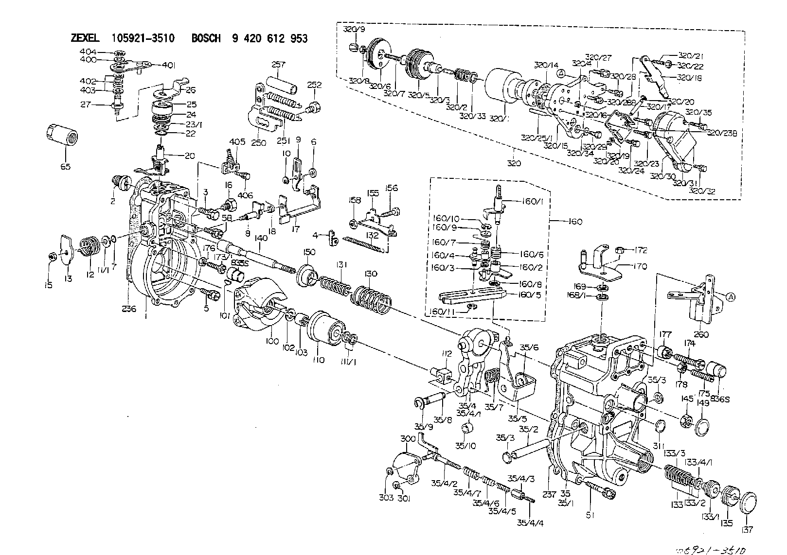
| 1. | [1] | 159200-4420 | GOVERNOR HOUSING |
| 2. | [1] | 154007-0200 | ADAPTOR |
| 3. | [1] | 020018-1840 | BLEEDER SCREW M8P1.25L18 |
| 4. | [1] | 159232-1600 | PLATE |
| 5. | [5] | 029010-6810 | BLEEDER SCREW |
| 5B. | [1] | 020106-1640 | BLEEDER SCREW M6P1.0L14 |
| 6. | [1] | 159242-0600 | BUSHING |
| 7. | [1] | 016530-1010 | O-RING |
| 8. | [1] | 159205-2821 | LEVER SHAFT |
| 9. | [1] | 159202-5401 | CONTROL LEVER |
| 10. | [1] | 016010-0810 | LOCKING WASHER |
| 11/1. | [0] | 029311-0220 | SHIM D18&10.3T0.2 |
| 11/1. | [0] | 029311-0230 | SHIM D18&10.3T0.5 |
| 11/1. | [0] | 029311-0430 | SHIM D18&10.3T0.30 |
| 11/1. | [0] | 029311-0440 | SHIM D18&10.3T0.40 |
| 11/1. | [0] | 029311-0450 | SHIM D18&10.3T0.25 |
| 11/1. | [0] | 029311-0460 | SHIM D18&10.3T0.35 |
| 11/1. | [0] | 139410-3300 | SHIM D18&10.3T0.6 |
| 11/1. | [0] | 139410-3400 | SHIM D18&10.3T0.8 |
| 11/1. | [0] | 139410-3500 | SHIM D18&10.3T0.9 |
| 12. | [1] | 159215-0500 | COILED SPRING |
| 13. | [1] | 159242-6601 | CONTROL LEVER |
| 15. | [1] | 013020-8040 | UNION NUT M8P1.25H7 |
| 16. | [1] | 159237-5500 | CAPSULE |
| 17. | [1] | 159202-4220 | CONTROL LEVER |
| 18. | [1] | 159215-0600 | COILED SPRING |
| 20. | [1] | 159242-7220 | CONTROL LEVER |
| 22. | [1] | 029631-0030 | O-RING &9.8W2.3 |
| 23/1. | [0] | 139410-1300 | SHIM D20.8&10.2T0.3 |
| 23/1. | [0] | 139410-1700 | SHIM D20.8&10.2T0.2 |
| 23/1. | [0] | 139410-1800 | SHIM D20.8&10.2T0.4 |
| 23/1. | [0] | 139410-2800 | SHIM D20.8&10.2T0.6 |
| 23/1. | [0] | 139410-3700 | SHIM D20.8&10.2T0.9 |
| 24. | [1] | 159215-3100 | COILED SPRING |
| 25. | [1] | 159235-5800 | CAP |
| 26. | [1] | 159249-5100 | CONTROL LEVER |
| 27. | [1] | 159227-7100 | BLEEDER SCREW |
| 35. | [1] | 159250-1120 | GOVERNOR COVER |
| 35/1. | [1] | 159201-9020 | GOVERNOR COVER |
| 35/2. | [1] | 159205-0400 | LEVER SHAFT |
| 35/3. | [2] | 159237-0200 | CAPSULE |
| 35/3. | [2] | 159237-0200 | CAPSULE |
| 35/4. | [1] | 159253-2420 | TENSIONING LEVER |
| 35/4/1. | [1] | 159253-2520 | TENSIONING LEVER |
| 35/4/2. | [1] | 159204-6322 | RACK |
| 35/4/3. | [1] | 159233-0300 | UNION NUT |
| 35/4/4. | [1] | 159234-0300 | FLAT-HEAD SCREW |
| 35/4/5. | [1] | 159216-0000 | COILED SPRING |
| 35/4/6. | [1] | 159216-0100 | COILED SPRING |
| 35/4/7. | [1] | 159216-0700 | COILED SPRING |
| 35/5. | [1] | 159203-5420 | GUIDE LEVER |
| 35/6. | [2] | 159235-5000 | BUSHING |
| 35/7. | [1] | 159215-1701 | COILED SPRING |
| 35/8. | [1] | 159231-1300 | BEARING PIN |
| 35/9. | [2] | 016010-0610 | LOCKING WASHER |
| 35/10. | [1] | 159238-2900 | BUSHING |
| 51. | [7] | 020106-3840 | BLEEDER SCREW |
| 65. | [1] | 154050-1720 | STOPPING DEVICE |
| 100. | [1] | 154100-9520 | FLYWEIGHT ASSEMBLY |
| 101. | [1] | 025803-1610 | WOODRUFF KEY |
| 102. | [1] | 029321-2020 | LOCKING WASHER |
| 103. | [1] | 029231-2030 | UNION NUT |
| 110. | [1] | 154123-2320 | SLIDING PIECE |
| 111/1. | [0] | 029311-0010 | SHIM D14&10.1T0.2 |
| 111/1. | [0] | 029311-0180 | SHIM D14&10.1T0.3 |
| 111/1. | [0] | 029311-0190 | SHIM D14&10.1T0.40 |
| 111/1. | [0] | 029311-0210 | SHIM D14&10.1T1 |
| 111/1. | [0] | 139410-0000 | SHIM D14.0&10.1T0.5 |
| 111/1. | [0] | 139410-0100 | SHIM D14.0&10.1T1.5 |
| 111/1. | [0] | 139410-3000 | SHIM D14&10.1T2.0 |
| 111/1. | [0] | 139410-3100 | SHIM D14&10.1T3.0 |
| 111/1. | [0] | 139410-3200 | SHIM D14&10.1T4.0 |
| 112. | [1] | 159236-0200 | TERMINAL STUD |
| 130. | [1] | 159210-2700 | COILED SPRING |
| 131. | [1] | 159211-2000 | GOVERNOR SPRING |
| 132. | [1] | 159214-0300 | COILED SPRING |
| 133. | [1] | 159212-3520 | SPRING PACK |
| 133/1. | [1] | 159234-5602 | GUIDE SLEEVE |
| 133/2. | [1] | 159212-3300 | COILED SPRING |
| 133/3. | [1] | 159212-3500 | COILED SPRING |
| 133/4/1. | [0] | 029310-9240 | SHIM D11.9&9T0.1 |
| 133/4/1. | [0] | 029310-9250 | SHIM D11.9&9T0.2 |
| 133/4/1. | [0] | 029310-9260 | SHIM D11.9&9T0.25 |
| 133/4/1. | [0] | 029310-9270 | SHIM D11.9&9T1.0 |
| 133/4/1. | [0] | 139409-0100 | SHIM D11.9&9T0.3 |
| 133/4/1. | [0] | 139409-0200 | SHIM D11.9&9T0.5 |
| 133/4/1. | [0] | 139409-0300 | SHIM D11.5&9T0.8 |
| 135. | [1] | 159248-2700 | FLAT-HEAD SCREW |
| 137. | [1] | 159237-5300 | CAPSULE |
| 140. | [1] | 159205-2101 | LEVER SHAFT |
| 145. | [1] | 159233-5700 | UNION NUT |
| 149. | [1] | 159237-5400 | CAPSULE |
| 150. | [1] | 159235-5300 | SLOTTED WASHER |
| 155. | [1] | 159204-6220 | STRAP |
| 156. | [1] | 159233-6020 | BLEEDER SCREW |
| 158. | [1] | 013020-5240 | UNION NUT M5P0.8H4 |
| 160. | [1] | 159252-2321 | LEVER GROUP |
| 160/1. | [1] | 159205-3921 | LEVER SHAFT |
| 160/2. | [1] | 159202-4420 | CONTROL LEVER |
| 160/3. | [1] | 029310-6030 | SHIM D11.5&6.2T0.2 |
| 160/4. | [1] | 159202-4520 | CONTROL LEVER |
| 160/5. | [1] | 159202-2200 | CONTROL LEVER |
| 160/6. | [1] | 159215-2600 | COILED SPRING |
| 160/7. | [1] | 159215-3600 | COILED SPRING |
| 160/8. | [1] | 016010-0810 | LOCKING WASHER |
| 160/9. | [1] | 014020-6140 | PLAIN WASHER |
| 160/10. | [1] | 016010-0610 | LOCKING WASHER |
| 160/11. | [1] | 016010-0810 | LOCKING WASHER |
| 168/1. | [0] | 139410-1200 | SHIM D26&10.2T0.3 |
| 168/1. | [0] | 139410-1900 | SHIM D26&10.2T0.2 |
| 168/1. | [0] | 139410-2000 | SHIM D26&10.2T0.4 |
| 168/1. | [0] | 139410-2400 | SHIM D26&10.2T0.35 |
| 168/1. | [0] | 139410-2500 | SHIM D26&10.2T0.25 |
| 168/1. | [0] | 139410-2900 | SHIM D26&10.2T0.6 |
| 169. | [1] | 139410-2100 | SHIM |
| 170. | [1] | 159260-3920 | CONTROL LEVER |
| 172. | [1] | 013020-8040 | UNION NUT M8P1.25H7 |
| 173/1. | [1] | 139006-3500 | BLEEDER SCREW M6P1.0L33 |
| 173/1. | [1] | 139006-3700 | BLEEDER SCREW M6P1.0L34 |
| 173/1. | [1] | 139006-3800 | BLEEDER SCREW M6P1.0L35 |
| 173/1. | [1] | 139006-3900 | BLEEDER SCREW M6P1.0L36 |
| 173/1. | [1] | 139006-5300 | BLEEDER SCREW M6P1.0L31 |
| 173/1. | [1] | 139006-5400 | BLEEDER SCREW M6P1.0L32 |
| 173/1. | [1] | 155615-2500 | BLEEDER SCREW M6P1.0L37 |
| 174. | [1] | 154010-8100 | BLEEDER SCREW M8P1.25L65 |
| 175. | [1] | 154010-0100 | FLAT-HEAD SCREW |
| 176. | [1] | 159225-8600 | UNION NUT |
| 177. | [1] | 154011-2300 | UNION NUT |
| 178. | [1] | 154011-0100 | HEXAGON NUT |
| 236. | [1] | 154390-0000 | GASKET |
| 237. | [1] | 159238-3100 | GASKET |
| 250. | [1] | 159227-5720 | BRACKET |
| 251. | [2] | 159243-5300 | COILED SPRING |
| 252. | [1] | 131329-0300 | BLEEDER SCREW |
| 257. | [2] | 154156-0500 | TUBE |
| 260. | [1] | 159226-6201 | BRACKET |
| 300. | [1] | 159281-0100 | CAM PLATE |
| 301. | [1] | 016010-0840 | LOCKING WASHER |
| 303. | [1] | 016010-0540 | LOCKING WASHER |
| 311. | [1] | 159237-0200 | CAPSULE |
| 320. | [1] | 155424-2320 | ANEROID CAPSULE |
| 320/1. | [1] | 155423-2520 | DIAPHRAGM HOUSING |
| 320/2. | [1] | 155423-9800 | COILED SPRING |
| 320/3. | [1] | 155423-0300 | STOP PIN |
| 320/4. | [1] | 016020-1220 | LOCKING WASHER |
| 320/5. | [1] | 155403-3021 | BELLOWS |
| 320/6. | [1] | 155403-3401 | COVER |
| 320/7. | [1] | 155423-1500 | SCREW PLUG |
| 320/8. | [1] | 029240-6010 | UNION NUT M6P1.0H5* |
| 320/9. | [1] | 154035-1600 | CAP NUT |
| 320/14. | [1] | 154390-2700 | GASKET |
| 320/15. | [1] | 155424-0000 | SPACER BUSHING |
| 320/16. | [1] | 155423-0800 | PLATE |
| 320/17. | [1] | 155423-0900 | LEVER SHAFT |
| 320/18. | [1] | 155423-1000 | CONTROL LEVER |
| 320/19. | [2] | 029310-4060 | SHIM |
| 320/20. | [2] | 016010-0440 | LOCKING WASHER |
| 320/20. | [2] | 016010-0440 | LOCKING WASHER |
| 320/21. | [1] | 155423-1100 | FLAT-HEAD SCREW |
| 320/22. | [1] | 013020-6010 | UNION NUT |
| 320/23. | [2] | 020105-2540 | BLEEDER SCREW |
| 320/23B. | [2] | 020105-2040 | BLEEDER SCREW M5P0.8L20 |
| 320/24. | [2] | 020105-0840 | BLEEDER SCREW M5P0.5L8 |
| 320/25/1. | [1] | 155423-1200 | STOP PIN L102 |
| 320/25/1. | [1] | 155424-4900 | STOP PIN L95 |
| 320/25/1. | [1] | 155424-5000 | STOP PIN L96 |
| 320/25/1B. | [1] | 155423-1300 | STOP PIN L102.5 |
| 320/25/1C. | [1] | 155423-1400 | STOP PIN L103 |
| 320/25/1D. | [1] | 155423-7600 | STOP PIN L103.5 |
| 320/25/1E. | [1] | 155423-7700 | STOP PIN L104 |
| 320/25/1F. | [1] | 155423-8700 | STOP PIN L97 |
| 320/25/1G. | [1] | 155423-8800 | STOP PIN L98 |
| 320/25/1H. | [1] | 155423-8900 | STOP PIN L99 |
| 320/25/1I. | [1] | 155423-9000 | STOP PIN L100 |
| 320/25/1J. | [1] | 155423-9100 | STOP PIN L101 |
| 320/27. | [1] | 020118-3040 | BLEEDER SCREW |
| 320/28. | [2] | 020106-2240 | BLEEDER SCREW |
| 320/28B. | [1] | 020106-1840 | BLEEDER SCREW M6P1L18 |
| 320/29. | [1] | 139006-1800 | BLEEDER SCREW |
| 320/30. | [1] | 154390-2800 | GASKET |
| 320/31. | [1] | 155424-0100 | COVER |
| 320/32. | [2] | 020105-1240 | BLEEDER SCREW M5P0.8L12 |
| 320/33. | [1] | 029311-2060 | SHIM D22&12.5T0.5 |
| 320/34. | [1] | 026506-1040 | GASKET D9.9&6.2T1 |
| 320/35. | [2] | 020105-2540 | BLEEDER SCREW |
| 400. | [2] | 139408-0800 | PLAIN WASHER D17&8.2T0.5 |
| 401. | [1] | 159249-5320 | CONTROL LEVER |
| 402. | [1] | 159227-7300 | COILED SPRING |
| 403. | [2] | 139408-0800 | PLAIN WASHER D17&8.2T0.5 |
| 404. | [1] | 016010-0840 | LOCKING WASHER |
| 405. | [1] | 159227-7020 | BRACKET |
| 406. | [2] | 020104-1040 | BLEEDER SCREW |
| 835S. | [1] | 154062-1900 | CAP D12L24 |
| 836S. | [1] | 154062-1700 | CAP D20L32 |
Include in #1:
101603-7082
as GOVERNOR
Cross reference number
Zexel num
Bosch num
Firm num
Name
105921-3510
1157704100 ISUZU
GOVERNOR
K 14JK MECHANICAL GOVERNOR GOV RLD GOV
K 14JK MECHANICAL GOVERNOR GOV RLD GOV
Information:
Table 1
Conversion Table
Current Hertz RPM
4.0 0 0
4.5 159 38
5.0 319 75
5.5 478 113
6.0 638 150
6.5 797 188
7.0 956 225
7.5 1116 263
8.0 1275 300
8.5 1434 338
9.0 1594 375
9.5 1753 413
10.0 1913 450
10.5 2072 488
11.0 2231 525
11.5 2391 563
12.0 2550 600
12.5 2709 638
13.0 2869 675
13.5 3028 713
14.0 3188 750
14.5 3347 788
15.0 3506 825
15.5 3666 863
16.0 3825 900
16.5 3984 938
17.0 4144 975
17.5 4303 1013
18.0 4463 1050
18.5 4622 1088
19.0 4781 1125
19.5 4941 1163
20.0 5100 1200
Illustration 5 g00562935
Calibrate the transmitter.
Disconnect the wiring from the transmitter.
Ensure that the resistor is located on the input side of the transmitter. The resistor should be across the positive terminal and the negative terminal.
Connect an ammeter and a signal generator as you are shown in illustration 5.
Ensure that the signal generator is not generating a signal (zero Hertz).
Adjust the zero dial until the ammeter reads 4 mA.
Adjust the signal generator in order to produce an output of 5100 HZ.
Adjust the span dial until the ammeter reads 20 mA.
Adjust the signal generator in order to produce an output of zero hertz. Verify that the ammeter reads 4 mA.
The ammeter reads 4 mA. STOP.
The ammeter does not read 4 mA. Proceed to 3.
Readjust the frequency input.
Adjust the signal generator in order to produce zero Hertz.
Adjust the zero dial until the ammeter reads 4 mA.
Adjust the signal generator in order to produce an output of 5100 HZ.
Adjust the span dial until the ammeter reads 20 mA.
Adjust the signal generator in order to produce an output of zero hertz. Verify that the ammeter reads 4 mA.Note: Repeat the procedure in order to calibrate a frequency transmitter properly. Continue until both the 4 mA and the 20 mA readings are correct.
The ammeter reads 4 mA and 20 mA at the desired input frequency. STOP.
The ammeter does not read 4 mA and 20 mA. Replace the transmitter. Verify that this repair eliminates the problem.Magnetic Pickup Sensor
The magnetic pickup sensor sends the engine speed signal to the engine speed switch and to the transmitter.
Illustration 6 g00562936
Setting and Adjustment
Adjust the sensor's clearance from the flywheel.
The engine is secured. Install the sensor until the sensor contacts the flywheel.
Back off the sensor (1.2 0.1 turns).
Measure clearance between the flywheel and the