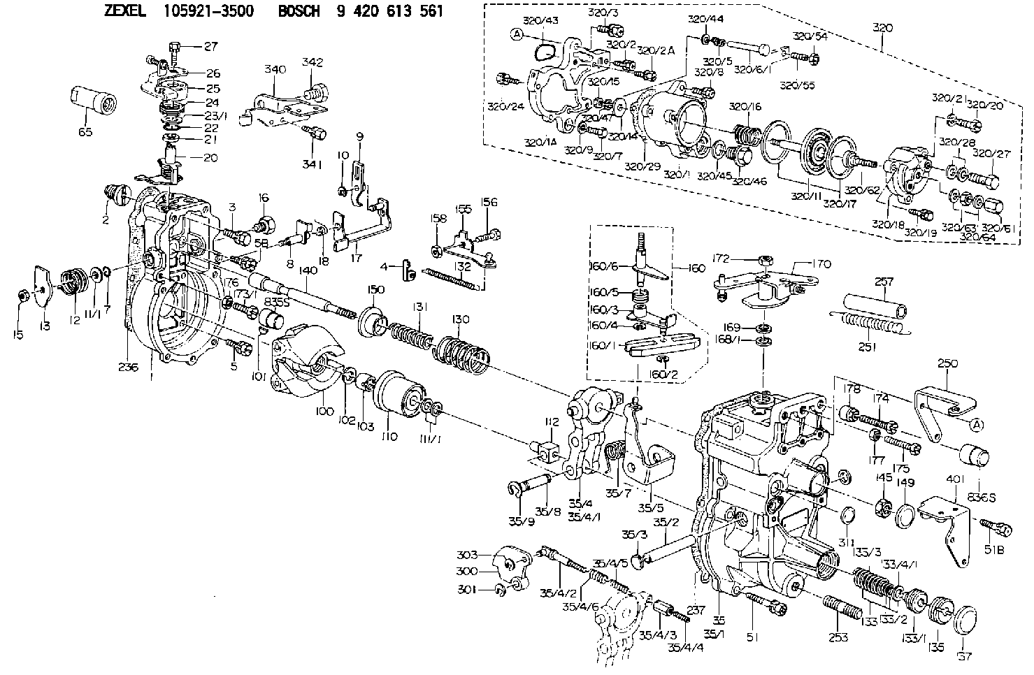
Information governor
BOSCH
9 420 613 561
9420613561
ZEXEL
105921-3500
1059213500
MITSUBISHI
ME726511
me726511

Rating:
Scheme ###:
| 1. | [1] | 159200-3220 | GOVERNOR HOUSING |
| 2. | [1] | 154007-0200 | ADAPTOR |
| 3. | [1] | 020018-1840 | BLEEDER SCREW M8P1.25L18 |
| 4. | [1] | 159232-2720 | PLATE |
| 5. | [5] | 029010-6810 | BLEEDER SCREW |
| 5B. | [1] | 020106-1640 | BLEEDER SCREW M6P1.0L14 |
| 7. | [1] | 016530-1010 | O-RING |
| 8. | [1] | 159205-2821 | LEVER SHAFT |
| 9. | [1] | 159202-2900 | CONTROL LEVER |
| 10. | [1] | 016010-0810 | LOCKING WASHER |
| 11/1. | [0] | 029311-0220 | SHIM D18&10.3T0.2 |
| 11/1. | [0] | 029311-0230 | SHIM D18&10.3T0.5 |
| 11/1. | [0] | 029311-0430 | SHIM D18&10.3T0.30 |
| 11/1. | [0] | 029311-0440 | SHIM D18&10.3T0.40 |
| 11/1. | [0] | 029311-0450 | SHIM D18&10.3T0.25 |
| 11/1. | [0] | 029311-0460 | SHIM D18&10.3T0.35 |
| 11/1. | [0] | 139410-3300 | SHIM D18&10.3T0.6 |
| 11/1. | [0] | 139410-3400 | SHIM D18&10.3T0.8 |
| 11/1. | [0] | 139410-3500 | SHIM D18&10.3T0.9 |
| 12. | [1] | 159215-0500 | COILED SPRING |
| 13. | [1] | 159242-6601 | CONTROL LEVER |
| 15. | [1] | 013020-8040 | UNION NUT M8P1.25H7 |
| 16. | [1] | 159237-5200 | CAPSULE |
| 17. | [1] | 159202-3320 | CONTROL LEVER |
| 18. | [1] | 159215-0600 | COILED SPRING |
| 20. | [1] | 159242-0920 | CONTROL LEVER |
| 21. | [1] | 159242-0600 | BUSHING |
| 22. | [1] | 029631-0030 | O-RING &9.8W2.3 |
| 23/1. | [0] | 029311-0220 | SHIM D18&10.3T0.2 |
| 23/1. | [0] | 029311-0230 | SHIM D18&10.3T0.5 |
| 23/1. | [0] | 029311-0430 | SHIM D18&10.3T0.30 |
| 23/1. | [0] | 029311-0440 | SHIM D18&10.3T0.40 |
| 23/1. | [0] | 029311-0450 | SHIM D18&10.3T0.25 |
| 23/1. | [0] | 029311-0460 | SHIM D18&10.3T0.35 |
| 23/1. | [0] | 139410-3300 | SHIM D18&10.3T0.6 |
| 23/1. | [0] | 139410-3400 | SHIM D18&10.3T0.8 |
| 23/1. | [0] | 139410-3500 | SHIM D18&10.3T0.9 |
| 24. | [1] | 159215-3000 | COILED SPRING |
| 25. | [1] | 159235-5800 | CAP |
| 26. | [1] | 159249-0320 | CONTROL LEVER |
| 27. | [1] | 020006-1640 | BLEEDER SCREW M6P1L16 4T |
| 35. | [1] | 159251-7520 | GOVERNOR COVER |
| 35/1. | [1] | 159201-5521 | GOVERNOR COVER |
| 35/2. | [1] | 159205-0400 | LEVER SHAFT |
| 35/3. | [2] | 159237-0200 | CAPSULE |
| 35/4. | [1] | 159253-1120 | TENSIONING LEVER |
| 35/4/1. | [1] | 159203-1120 | TENSIONING LEVER |
| 35/4/2. | [1] | 159204-5021 | RACK |
| 35/4/3. | [1] | 159233-0300 | UNION NUT |
| 35/4/4. | [1] | 159234-0300 | FLAT-HEAD SCREW |
| 35/4/5. | [1] | 159216-0000 | COILED SPRING |
| 35/4/6. | [1] | 159216-0100 | COILED SPRING |
| 35/5. | [1] | 159203-6020 | GUIDE LEVER |
| 35/7. | [1] | 159215-1701 | COILED SPRING |
| 35/8. | [1] | 159231-2000 | BEARING PIN |
| 35/9. | [2] | 016010-0610 | LOCKING WASHER |
| 51. | [6] | 020106-3840 | BLEEDER SCREW |
| 51B. | [1] | 020106-4040 | BLEEDER SCREW |
| 65. | [1] | 154050-1720 | STOPPING DEVICE |
| 100. | [1] | 154101-0420 | FLYWEIGHT ASSEMBLY |
| 101. | [1] | 025803-1610 | WOODRUFF KEY |
| 102. | [1] | 029321-2020 | LOCKING WASHER |
| 103. | [1] | 029231-2030 | UNION NUT |
| 110. | [1] | 154123-2320 | SLIDING PIECE |
| 111/1. | [0] | 029311-0010 | SHIM D14&10.1T0.2 |
| 111/1. | [0] | 029311-0180 | SHIM D14&10.1T0.3 |
| 111/1. | [0] | 029311-0190 | SHIM D14&10.1T0.40 |
| 111/1. | [0] | 029311-0210 | SHIM D14&10.1T1 |
| 111/1. | [0] | 139410-0000 | SHIM D14.0&10.1T0.5 |
| 111/1. | [0] | 139410-0100 | SHIM D14.0&10.1T1.5 |
| 111/1. | [0] | 139410-3000 | SHIM D14&10.1T2.0 |
| 111/1. | [0] | 139410-3100 | SHIM D14&10.1T3.0 |
| 111/1. | [0] | 139410-3200 | SHIM D14&10.1T4.0 |
| 112. | [1] | 159236-0200 | TERMINAL STUD |
| 130. | [1] | 159210-5300 | GOVERNOR SPRING |
| 131. | [1] | 159211-3300 | GOVERNOR SPRING |
| 132. | [1] | 159214-0100 | COILED SPRING |
| 133. | [1] | 159212-4920 | SPRING PACK |
| 133/1. | [1] | 159234-5602 | GUIDE SLEEVE |
| 133/2. | [1] | 159212-4500 | COILED SPRING |
| 133/3. | [1] | 159212-3500 | COILED SPRING |
| 133/4/1. | [0] | 029310-9240 | SHIM D11.9&9T0.1 |
| 133/4/1. | [0] | 029310-9250 | SHIM D11.9&9T0.2 |
| 133/4/1. | [0] | 029310-9260 | SHIM D11.9&9T0.25 |
| 133/4/1. | [0] | 029310-9270 | SHIM D11.9&9T1.0 |
| 133/4/1. | [0] | 139409-0100 | SHIM D11.9&9T0.3 |
| 133/4/1. | [0] | 139409-0200 | SHIM D11.9&9T0.5 |
| 133/4/1. | [0] | 139409-0300 | SHIM D11.5&9T0.8 |
| 135. | [1] | 159248-2700 | FLAT-HEAD SCREW |
| 137. | [1] | 159237-5300 | CAPSULE |
| 140. | [1] | 159205-2101 | LEVER SHAFT |
| 145. | [1] | 159233-5700 | UNION NUT |
| 149. | [1] | 159237-5400 | CAPSULE |
| 150. | [1] | 159235-5300 | SLOTTED WASHER |
| 155. | [1] | 159204-7820 | STRAP |
| 156. | [1] | 159233-5800 | BLEEDER SCREW |
| 158. | [1] | 013020-5240 | UNION NUT M5P0.8H4 |
| 160. | [1] | 159252-1221 | LEVER GROUP |
| 160/1. | [1] | 159202-2200 | CONTROL LEVER |
| 160/2. | [1] | 016010-0810 | LOCKING WASHER |
| 160/3. | [1] | 159202-3120 | CONTROL LEVER |
| 160/4. | [1] | 016010-0810 | LOCKING WASHER |
| 160/5. | [1] | 159215-2600 | COILED SPRING |
| 160/6. | [1] | 159205-3012 | LEVER SHAFT |
| 168/1. | [0] | 029311-0640 | SHIM D26.0&10.2T0.95 |
| 168/1. | [0] | 029311-0650 | SHIM D26.0&10.2T0.20 |
| 168/1. | [0] | 029311-0660 | SHIM D26.0&10.2T0.25 |
| 168/1. | [0] | 029311-0670 | SHIM D26.0&10.2T0.30 |
| 168/1. | [0] | 029311-0680 | SHIM D26.0&10.2T0.35 |
| 168/1. | [0] | 029311-0690 | SHIM D26.0&10.2T0.40 |
| 168/1. | [0] | 029311-0700 | SHIM D26.0&10.2T0.50 |
| 168/1. | [0] | 139410-1400 | SHIM D26&10.2T0.7 |
| 168/1. | [0] | 139410-1500 | SHIM D26&10.2T0.9 |
| 168/1. | [0] | 139410-1600 | SHIM D26&10.2T0.8 |
| 168/1. | [0] | 139410-2700 | SHIM D26&10.2T0.6 |
| 169. | [1] | 139410-2300 | SHIM |
| 170. | [1] | 159244-8520 | CONTROL LEVER |
| 172. | [1] | 013020-8040 | UNION NUT M8P1.25H7 |
| 173/1. | [1] | 139006-3500 | BLEEDER SCREW M6P1.0L33 |
| 173/1. | [1] | 139006-3700 | BLEEDER SCREW M6P1.0L34 |
| 173/1. | [1] | 139006-3800 | BLEEDER SCREW M6P1.0L35 |
| 173/1. | [1] | 139006-3900 | BLEEDER SCREW M6P1.0L36 |
| 173/1. | [1] | 139006-5300 | BLEEDER SCREW M6P1.0L31 |
| 173/1. | [1] | 139006-5400 | BLEEDER SCREW M6P1.0L32 |
| 173/1. | [1] | 155615-2500 | BLEEDER SCREW M6P1.0L37 |
| 174. | [1] | 154010-7200 | BLEEDER SCREW M8P1.25L62 |
| 175. | [1] | 154010-2900 | BLEEDER SCREW |
| 176. | [1] | 159225-8600 | UNION NUT |
| 177. | [1] | 154011-2300 | UNION NUT |
| 178. | [1] | 154011-0100 | HEXAGON NUT |
| 236. | [1] | 154390-0000 | GASKET |
| 237. | [1] | 159238-3100 | GASKET |
| 250. | [1] | 159226-9620 | BRACKET |
| 251. | [1] | 159243-6400 | COILED SPRING |
| 253. | [1] | 139010-0000 | STUD |
| 257. | [1] | 154156-0500 | TUBE |
| 300. | [1] | 159281-0200 | CAM PLATE |
| 301. | [1] | 016010-0840 | LOCKING WASHER |
| 303. | [1] | 016010-0540 | LOCKING WASHER |
| 311. | [1] | 159237-0200 | CAPSULE |
| 320. | [1] | 154419-2421 | MANIFOLD-PRESSURE COMP. |
| 320/1. | [1] | 154412-0821 | DIAPHRAGM HOUSING |
| 320/1A. | [1] | 154413-2701 | SPACER BUSHING |
| 320/2. | [1] | 020106-2240 | BLEEDER SCREW |
| 320/2A. | [1] | 020106-2540 | BLEEDER SCREW M6P1L25 |
| 320/3. | [1] | 020118-3040 | BLEEDER SCREW |
| 320/5. | [1] | 159275-1400 | COILED SPRING |
| 320/6/1. | [1] | 159274-0120 | STOP PIN L125 |
| 320/6/1. | [1] | 159274-0220 | STOP PIN L127.50 |
| 320/6/1. | [1] | 159274-0320 | STOP PIN L128.00 |
| 320/6/1. | [1] | 159274-0420 | STOP PIN L127.00 |
| 320/6/1. | [1] | 159274-0520 | STOP PIN L126.00 |
| 320/6/1. | [1] | 159274-0620 | STOP PIN L129.00 |
| 320/6/1. | [1] | 159274-0720 | STOP PIN L128.50 |
| 320/6/1. | [1] | 159274-0820 | STOP PIN L125.50 |
| 320/6/1. | [1] | 159274-0920 | STOP PIN L126.50 |
| 320/6/1. | [1] | 159274-1120 | STOP PIN L119.5 |
| 320/6/1. | [1] | 159274-1220 | STOP PIN L120 |
| 320/6/1. | [1] | 159274-1320 | STOP PIN L120.5 |
| 320/6/1. | [1] | 159274-1420 | STOP PIN L121 |
| 320/6/1. | [1] | 159274-1520 | STOP PIN L121.5 |
| 320/6/1. | [1] | 159274-1620 | STOP PIN L122 |
| 320/6/1. | [1] | 159274-1720 | STOP PIN L122.5 |
| 320/6/1. | [1] | 159274-1820 | STOP PIN L123 |
| 320/6/1. | [1] | 159274-1920 | STOP PIN L123.5 |
| 320/6/1. | [1] | 159274-4220 | STOP PIN L129.5 |
| 320/6/1. | [1] | 159274-4320 | STOP PIN L130 |
| 320/6/1. | [1] | 159274-4420 | STOP PIN L130.5 |
| 320/6/1. | [1] | 159274-4520 | STOP PIN L131 |
| 320/6/1. | [1] | 159274-4620 | STOP PIN L131.5 |
| 320/6/1. | [1] | 159274-4720 | STOP PIN L132 |
| 320/6/1. | [1] | 159274-4820 | STOP PIN L132.5 |
| 320/6/1. | [1] | 159274-4920 | STOP PIN L133 |
| 320/6/1. | [1] | 159274-5020 | STOP PIN L133.5 |
| 320/7. | [1] | 020306-1640 | BLEEDER SCREW |
| 320/8. | [3] | 020106-2240 | BLEEDER SCREW |
| 320/9. | [1] | 139505-0000 | PLAIN WASHER |
| 320/11. | [1] | 154400-8521 | DIAPHRAGM |
| 320/14. | [1] | 154406-5500 | SLOTTED WASHER |
| 320/15. | [1] | 013030-6010 | UNION NUT |
| 320/16. | [1] | 154403-2800 | COILED SPRING |
| 320/17. | [2] | 154413-2600 | GASKET |
| 320/18. | [1] | 154404-5000 | COVER |
| 320/19. | [1] | 020106-2040 | BLEEDER SCREW M6P1L20 |
| 320/20. | [2] | 139006-7000 | BLEEDER SCREW |
| 320/21. | [2] | 014110-6440 | LOCKING WASHER |
| 320/24. | [2] | 020106-2540 | BLEEDER SCREW M6P1L25 |
| 320/27. | [1] | 029731-0180 | EYE BOLT |
| 320/28. | [2] | 026510-1340 | GASKET D13.4&10.2T1 |
| 320/29. | [1] | 154413-2501 | GASKET |
| 320/43. | [1] | 159226-4500 | SPACER RING |
| 320/44. | [1] | 014010-5140 | PLAIN WASHER D12&5.5T0.8 |
| 320/45. | [1] | 029331-8040 | GASKET |
| 320/46. | [1] | 154406-5800 | FLAT-HEAD SCREW |
| 320/47. | [1] | 014110-6440 | LOCKING WASHER |
| 320/54. | [1] | 013030-6040 | UNION NUT M6P1H3.6 |
| 320/55. | [1] | 154404-4800 | FLAT-HEAD SCREW |
| 320/61. | [1] | 154035-1600 | CAP NUT |
| 320/62. | [1] | 154404-4400 | FLAT-HEAD SCREW |
| 320/63. | [1] | 013030-6040 | UNION NUT M6P1H3.6 |
| 320/64. | [2] | 026506-1040 | GASKET D9.9&6.2T1 |
| 340. | [1] | 159245-5600 | BRACKET |
| 341. | [2] | 020104-1040 | BLEEDER SCREW |
| 342. | [1] | 159248-0200 | BLEEDER SCREW |
| 401. | [1] | 159226-5520 | BRACKET |
| 835S. | [1] | 154062-1900 | CAP D12L24 |
| 836S. | [1] | 154062-1700 | CAP D20L32 |
Include in #1:
101401-1431
as GOVERNOR
Cross reference number
Zexel num
Bosch num
Firm num
Name
Information:
Shutdowns
A shutdown secures the fuel and a shutdown secures the air to the engine. A fuel shutoff solenoid may be located in the fuel actuator. The fuel shutoff solenoid is energized. The injector is driven to the off position. This secures the fuel.The air shutoff solenoid secures the air. When this solenoid is activated compressed air flows to the air damper. The air releases a pin. When the pin is released, a spring closes the air damper. This secures the combustion air supply from the turbochargers to the aftercooler.Note: The air damper must be MANUALLY reset before the engine can be restarted. The Marine Engine Control Panel must also be reset with the "RESET" switch before the MMS will allow starting. The panel may not be reset until the engine has stopped rotating. Determine the cause of the shutdown and correct the problem prior to engine operation.
Table 2
Shutdowns of the Marine Monitoring System
Description Sensor Location
Group Part Number (1) Set Point Source of the Alarm
Pressure
Low Oil Pressure 142-5916 or 146-9438 Block 1
105 kPa (15 psi) @LS
260 kPa (38) @HS Low Speed Oil Contactor or High Speed Oil Contactor, or the Lube Oil Filter Outlet Pressure Transducer
High Crankcase Pressure 147-2369 In-line 142-5919 Vee
1 kPa (.15 psi) Crankcase pressure contactor
Temperature
High Jacket Water Outlet Temperature 142-5916 or 146-9438 Block 4
109 °C (228 °F) Jacket Water Contactor or Optional Transducer
Miscellaneous
Oil Mist Detector Various Contact Closure Oil Mist Detector - Not in all engines
Overspeed 146-5522, 146-5523, 146-5524, 146-5525 113% of Rated Speed Engine Speed Switch and MMS
Metal Particle Detection Basic Engine Metal Particles in Oil Plus 5 Seconds Metal Particle Detector
( 1 ) The group part numbers are provided for reference only. For individual part numbers see Reference Information, "Reference Parts Information".Low Speed - The engine speed is below 75% of the rated engine speed.High Speed - The engine speed is above 75% of the rated engine speed.The "Sensor Failure Alarm" Screen
The "Sensor Failure Alarm" screen is displayed when unexpected signals are received by the PLC. The alarm monitors sensors which can produce alarms or shutdowns.
Table 3
Sensor Failure Alarms for the Marine Monitoring System
Description Sensor Location
Group Part Number (1) Set Point Source of the Alarm
RTD/PT 100 Failures Various
< -50 °C (-58 °F) or
> 150 °C (302 °F) Lube oil, After Cooler/Oil Cooler, Jacket Water, and Inlet Manifold Temperatures
Thermocouples Various
< -50 °C (-58 °F) or
> 700 °C (1292 °F) Individual Cylinder, Pre-Turbine, and Stack Thermocouples
4-20mA Transducers Various < 3.5 mA or > 20.15 mA Engine Speed Transducer, Lube Oil and Fuel pressure transducers
Contactors Various No signal