Information governor
ZEXEL
105921-1870
1059211870
HINO
223003800A
223003800a
Rating:
Scheme ###:
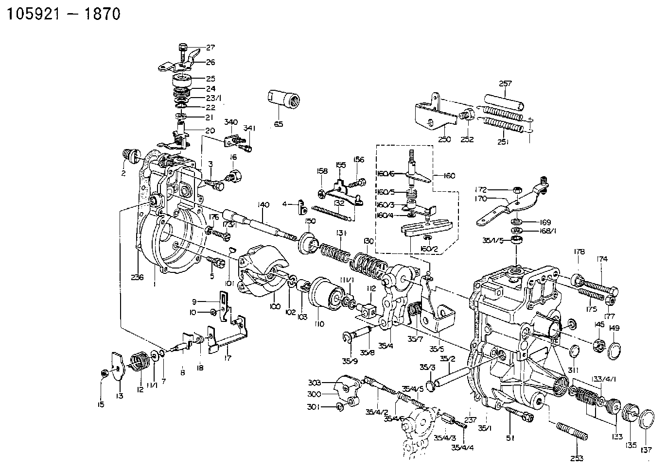
| 1. | [1] | 159200-3220 | GOVERNOR HOUSING |
| 2. | [1] | 154007-0200 | ADAPTOR |
| 3. | [1] | 020018-1840 | BLEEDER SCREW |
| 4. | [1] | 159232-0400 | PLATE |
| 5. | [6] | 029010-6810 | BLEEDER SCREW |
| 7. | [1] | 016530-1010 | O-RING |
| 8. | [1] | 159205-2820 | LEVER SHAFT |
| 9. | [1] | 159202-2900 | CONTROL LEVER |
| 10. | [1] | 016010-0810 | LOCKING WASHER |
| 11/1. | [1] | 029311-0220 | SHIM |
| 11/1. | [1] | 029311-0230 | SHIM |
| 11/1. | [1] | 029311-0430 | SHIM |
| 11/1. | [1] | 029311-0440 | SHIM |
| 11/1. | [1] | 029311-0450 | SHIM |
| 11/1. | [1] | 029311-0460 | SHIM |
| 12. | [1] | 159215-0500 | COILED SPRING |
| 13. | [1] | 159242-6601 | CONTROL LEVER |
| 15. | [1] | 013020-8040 | UNION NUT |
| 16. | [1] | 159237-5200 | CAPSULE |
| 17. | [1] | 159202-3020 | CONTROL LEVER |
| 18. | [1] | 159215-0600 | COILED SPRING |
| 20. | [1] | 159242-0920 | CONTROL LEVER |
| 21. | [1] | 159242-0600 | BUSHING |
| 22. | [1] | 029631-0030 | O-RING |
| 23/1. | [1] | 029311-0220 | SHIM |
| 23/1. | [1] | 029311-0230 | SHIM |
| 23/1. | [1] | 029311-0430 | SHIM |
| 23/1. | [1] | 029311-0440 | SHIM |
| 23/1. | [1] | 029311-0450 | SHIM |
| 23/1. | [1] | 029311-0460 | SHIM |
| 24. | [1] | 159215-3000 | COILED SPRING |
| 25. | [1] | 159235-5800 | CAP |
| 26. | [1] | 159249-2500 | CONTROL LEVER |
| 27. | [1] | 020006-1640 | BLEEDER SCREW |
| 35. | [1] | 159251-5520 | GOVERNOR COVER |
| 35/1. | [1] | 159201-5022 | GOVERNOR COVER |
| 35/1/5. | [1] | 029621-0080 | PACKING RING |
| 35/2. | [1] | 159205-0400 | LEVER SHAFT |
| 35/3. | [2] | 139902-0000 | CAPSULE |
| 35/4. | [1] | 159253-0820 | TENSIONING LEVER |
| 35/4/2. | [1] | 159204-5020 | RACK |
| 35/4/3. | [1] | 159233-0300 | UNION NUT |
| 35/4/4. | [1] | 159234-0300 | FLAT-HEAD SCREW |
| 35/4/5. | [1] | 159216-0000 | COILED SPRING |
| 35/4/6. | [1] | 159216-0100 | COILED SPRING |
| 35/5. | [1] | 159203-6020 | GUIDE LEVER |
| 35/7. | [1] | 159215-1700 | COILED SPRING |
| 35/8. | [1] | 159231-2000 | BEARING PIN |
| 35/9. | [2] | 016010-0610 | LOCKING WASHER |
| 51. | [7] | 020106-3840 | BLEEDER SCREW |
| 65. | [1] | 154050-1720 | STOPPING DEVICE |
| 100. | [1] | 154100-5020 | FLYWEIGHT ASSEMBLY |
| 101. | [1] | 025803-1610 | WOODRUFF KEY |
| 102. | [1] | 029321-2020 | LOCKING WASHER |
| 103. | [1] | 029231-2030 | UNION NUT |
| 110. | [1] | 154123-2320 | SLIDING PIECE |
| 111/1. | [1] | 029311-0010 | SHIM |
| 111/1. | [1] | 029311-0180 | SHIM |
| 111/1. | [1] | 029311-0190 | SHIM |
| 111/1. | [1] | 029311-0210 | SHIM |
| 111/1. | [1] | 139410-0000 | SHIM |
| 111/1. | [1] | 139410-0100 | SHIM |
| 112. | [1] | 159236-0200 | TERMINAL STUD |
| 130. | [1] | 159210-0500 | GOVERNOR SPRING K=4.7 |
| 131. | [1] | 159211-1900 | GOVERNOR SPRING K=0.7 |
| 132. | [1] | 159214-0000 | COILED SPRING |
| 133. | [1] | 159212-5520 | SPRING PACK |
| 135. | [1] | 159248-2700 | FLAT-HEAD SCREW |
| 137. | [1] | 159237-5300 | CAPSULE |
| 140. | [1] | 159205-2100 | LEVER SHAFT |
| 145. | [1] | 159233-5700 | UNION NUT |
| 149. | [1] | 159237-5400 | CAPSULE |
| 150. | [1] | 159235-0000 | SPRING SEAT |
| 155. | [1] | 159204-5620 | STRAP |
| 156. | [1] | 159233-5800 | BLEEDER SCREW |
| 158. | [1] | 013020-5240 | UNION NUT |
| 160. | [1] | 159252-1120 | LEVER GROUP |
| 160/2. | [1] | 016010-0810 | LOCKING WASHER |
| 160/3. | [1] | 159202-3120 | CONTROL LEVER |
| 160/4. | [1] | 016010-0810 | LOCKING WASHER |
| 160/5. | [1] | 159215-2600 | COILED SPRING |
| 160/6. | [1] | 159205-2921 | LEVER SHAFT |
| 168/1. | [1] | 029311-0640 | SHIM |
| 168/1. | [1] | 029311-0650 | SHIM |
| 168/1. | [1] | 029311-0660 | SHIM |
| 168/1. | [1] | 029311-0670 | SHIM |
| 168/1. | [1] | 029311-0680 | SHIM |
| 168/1. | [1] | 029311-0690 | SHIM |
| 168/1. | [1] | 029311-0700 | SHIM |
| 168/1. | [1] | 139410-1400 | SHIM |
| 168/1. | [1] | 139410-1500 | SHIM |
| 168/1. | [1] | 139410-1600 | SHIM |
| 169. | [1] | 029301-0370 | PLAIN WASHER |
| 170. | [1] | 159244-6220 | CONTROL LEVER |
| 172. | [1] | 013020-8040 | UNION NUT |
| 173/1. | [1] | 139006-3500 | BLEEDER SCREW |
| 173/1. | [1] | 139006-3700 | BLEEDER SCREW |
| 173/1. | [1] | 139006-3800 | BLEEDER SCREW |
| 173/1. | [1] | 139006-3900 | BLEEDER SCREW |
| 173/1. | [1] | 155615-2500 | BLEEDER SCREW |
| 174. | [1] | 154010-7200 | BLEEDER SCREW |
| 175. | [1] | 154010-0100 | FLAT-HEAD SCREW |
| 176. | [1] | 159225-8600 | UNION NUT |
| 177. | [1] | 154011-2300 | UNION NUT |
| 178. | [1] | 154011-0100 | HEXAGON NUT |
| 236. | [1] | 154390-0000 | GASKET |
| 237. | [1] | 159238-3100 | GASKET |
| 250. | [1] | 159226-6320 | BRACKET |
| 251. | [2] | 159243-2500 | COILED SPRING |
| 252. | [1] | 159248-3000 | BLEEDER SCREW |
| 253. | [1] | 139010-0000 | STUD |
| 257. | [2] | 154156-0600 | TUBE |
| 300. | [1] | 159209-0200 | CAM PLATE |
| 301. | [1] | 016010-0840 | LOCKING WASHER |
| 303. | [1] | 016010-0540 | LOCKING WASHER |
| 311. | [1] | 139902-0000 | CAPSULE |
| 340. | [1] | 159226-9720 | BRACKET |
| 341. | [2] | 020104-1040 | BLEEDER SCREW |
Include in #1:
101601-5230
as GOVERNOR
Cross reference number
Zexel num
Bosch num
Firm num
Name
Information:
7. Remove inner fuel lines (13). 8. Remove Jacobs washers (14) and Jacobs shims (15) from the Jacobs stud assemblies. 9. Remove bolt (17) and two Jacobs stud assemblies (16) that hold the rocker shaft assembly to the head. Remove rocker shaft assembly (18). 10. Remove Jacobs exhaust valve bridges (20) from the exhaust valves only. The intake valves have the Caterpillar intake valve bridges. Remove the Caterpillar intake valve bridges (19).Install Jacobs Engine Brake
Do each step for each end of the engine. The front half is shown.1. Put clean engine oil on the bridges and dowels.2. Install Jacobs exhaust valve bridges (20) and the Caterpillar intake valve bridges (19) on the dowels.3. Keep hand pressure on the bridges, and turn the adjustment screw clockwise until contact is made with the valve stem. Turn the screw an extra 20° to 30°. This will make the dowel straight in the guide and compensate for gap (slack) in the threads. Hold the adjustment screw in this position, and tighten the locknut to a torque of 28 4 N m (21 3 lb.ft.). 4. Put rocker shaft assembly (18) in position on the cylinder head. 5. Install Jacobs washers (21) on the Jacobs stud assemblies (16). Put clean oil on the threads, and install washer and bolt (17) and Jacobs stud assemblies (16). Tighten the center bolt and Jacobs stud assemblies in increments of 70 N m (50 lb.ft.) each until a final torque of 450 N m (330 lb.ft.) is obtained.6. Make an adjustment to the valves to have a clearance of .015 (0.38 mm) for the intake valves and .030 (0.76 mm) for the exhaust valves. Tighten the locknuts to a torque of 28 4 N m (21 3 lb.ft.), and check the valve clearance again. See Testing And Adjusting for the correct procedure. 7. Install a new Jacobs O-ring seal (22) on the Jacobs oil supply adapter in the rocker shaft assembly. Put clean oil on the Jacobs O-ring seal.
Do not cause damage to the O-ring seals on the inner fuel lines.
8. Install inner fuel lines (13). Tighten the fuel line nuts to a torque of 40 7 N m (30 5 lb.ft.) with tooling (A) and (B). The Jacobs brake for the 3406B Truck Engine has only one support bracket (11).9. Put jacobs support brackets (11) in position as shown. Put oil on the threads of Jacobs bolts (12). Install the washers on the Jacobs bolts. Install Jacobs bolts (12) that hold the Jacobs support bracket in place. Tighten the Jacobs bolts to a torque of 450 N m (330 lb.ft.). 10. Install Jacobs washers (14) on the Jacobs stud assemblies.
Be extra careful not to cause damage to the Jacobs oil supply adapter O-ring seal when the Jacobs brake housing assembly is installed.
The brake housing assembly with the mark "FRONT" on it must be installed on the front three cylinders. The brake housing assembly with the mark "REAR" must be installed