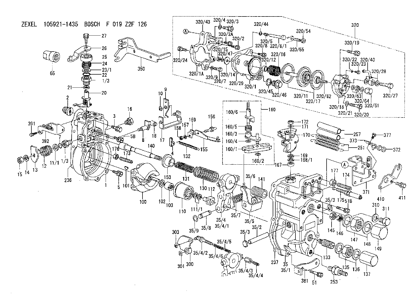
Information governor
BOSCH
F 019 Z2F 126
f019z2f126
ZEXEL
105921-1435
1059211435
Rating:
Scheme ###:
| 1. | [1] | 159200-3320 | GOVERNOR HOUSING |
| 1/3. | [2] | 154321-2600 | BUSHING |
| 1/3. | [2] | 154321-2600 | BUSHING |
| 2. | [1] | 154007-0200 | ADAPTOR |
| 3. | [1] | 020018-1840 | BLEEDER SCREW M8P1.25L18 |
| 4. | [1] | 159232-0401 | PLATE |
| 5. | [5] | 029010-6810 | BLEEDER SCREW |
| 5B. | [1] | 020106-1640 | BLEEDER SCREW M6P1.0L14 |
| 7. | [1] | 029631-0030 | O-RING &9.8W2.3 |
| 8. | [1] | 159205-2821 | LEVER SHAFT |
| 9. | [1] | 159202-1301 | CONTROL LEVER |
| 10. | [1] | 016010-0810 | LOCKING WASHER |
| 11/1. | [0] | 029311-0520 | SHIM D20.8&10.3T0.2 |
| 11/1. | [0] | 029311-0530 | SHIM D20.8&10.3T0.25 |
| 11/1. | [0] | 029311-0540 | SHIM D20.8&10.3T0.3 |
| 11/1. | [0] | 029311-0550 | SHIM D20.8&10.3T0.35 |
| 11/1. | [0] | 029311-0560 | SHIM D20.8&10.3T0.4 |
| 11/1. | [0] | 029311-0570 | SHIM D20.8&10.3T0.5 |
| 12. | [1] | 159215-0500 | COILED SPRING |
| 13. | [1] | 159242-0100 | CONTROL LEVER |
| 14. | [1] | 014110-8440 | LOCKING WASHER |
| 15. | [1] | 013020-8040 | UNION NUT M8P1.25H7 |
| 16. | [1] | 159237-0000 | CAPSULE |
| 17. | [1] | 159202-1020 | CONTROL LEVER |
| 18. | [1] | 159215-0600 | COILED SPRING |
| 20. | [1] | 159242-0920 | CONTROL LEVER |
| 21. | [1] | 159242-0600 | BUSHING |
| 22. | [1] | 029631-0030 | O-RING &9.8W2.3 |
| 23/1. | [0] | 029311-0520 | SHIM D20.8&10.3T0.2 |
| 23/1. | [0] | 029311-0530 | SHIM D20.8&10.3T0.25 |
| 23/1. | [0] | 029311-0540 | SHIM D20.8&10.3T0.3 |
| 23/1. | [0] | 029311-0550 | SHIM D20.8&10.3T0.35 |
| 23/1. | [0] | 029311-0560 | SHIM D20.8&10.3T0.4 |
| 23/1. | [0] | 029311-0570 | SHIM D20.8&10.3T0.5 |
| 24. | [1] | 159215-0500 | COILED SPRING |
| 25. | [1] | 154322-0100 | CAP |
| 26. | [1] | 159249-1220 | CONTROL LEVER |
| 27. | [1] | 020006-1640 | BLEEDER SCREW M6P1L16 4T |
| 35. | [1] | 159251-4820 | GOVERNOR COVER |
| 35/1. | [1] | 159201-4120 | GOVERNOR COVER |
| 35/2. | [1] | 159205-0400 | LEVER SHAFT |
| 35/3. | [2] | 159237-0200 | CAPSULE |
| 35/3. | [2] | 159237-0200 | CAPSULE |
| 35/4. | [1] | 159253-0520 | TENSIONING LEVER |
| 35/4/1. | [1] | 159203-0620 | TENSIONING LEVER |
| 35/4/2. | [1] | 159204-5021 | RACK |
| 35/4/3. | [1] | 159233-0300 | UNION NUT |
| 35/4/4. | [1] | 159234-0000 | FLAT-HEAD SCREW |
| 35/4/5. | [1] | 159216-0000 | COILED SPRING |
| 35/4/6. | [1] | 159216-0100 | COILED SPRING |
| 35/5. | [1] | 159203-5120 | GUIDE LEVER |
| 35/6. | [2] | 159235-5000 | BUSHING |
| 35/7. | [1] | 159215-0201 | COILED SPRING |
| 35/8. | [1] | 159231-0800 | BEARING PIN |
| 35/9. | [2] | 016010-0610 | LOCKING WASHER |
| 51. | [5] | 020106-3840 | BLEEDER SCREW |
| 51B. | [2] | 020106-4540 | BLEEDER SCREW M6P1.0L45 |
| 65. | [1] | 154050-1720 | STOPPING DEVICE |
| 100. | [1] | 154101-1220 | FLYWEIGHT ASSEMBLY |
| 101. | [1] | 025803-1610 | WOODRUFF KEY |
| 102. | [1] | 029321-2020 | LOCKING WASHER |
| 103. | [1] | 029231-2030 | UNION NUT |
| 110. | [1] | 154123-2320 | SLIDING PIECE |
| 111/1. | [0] | 029311-0010 | SHIM D14&10.1T0.2 |
| 111/1. | [0] | 029311-0180 | SHIM D14&10.1T0.3 |
| 111/1. | [0] | 029311-0190 | SHIM D14&10.1T0.40 |
| 111/1. | [0] | 029311-0210 | SHIM D14&10.1T1 |
| 111/1. | [0] | 139410-0000 | SHIM D14.0&10.1T0.5 |
| 111/1. | [0] | 139410-0100 | SHIM D14.0&10.1T1.5 |
| 111/1. | [0] | 139410-3000 | SHIM D14&10.1T2.0 |
| 111/1. | [0] | 139410-3100 | SHIM D14&10.1T3.0 |
| 111/1. | [0] | 139410-3200 | SHIM D14&10.1T4.0 |
| 112. | [1] | 159236-0100 | TERMINAL STUD |
| 130. | [1] | 159210-5600 | GOVERNOR SPRING |
| 131. | [1] | 159211-4200 | GOVERNOR SPRING |
| 132. | [1] | 159214-0100 | COILED SPRING |
| 133. | [1] | 159212-1220 | HEADLESS SCREW |
| 135. | [1] | 139220-0200 | UNION NUT |
| 136. | [2] | 026520-2440 | GASKET D23.9&20.2T1 |
| 137. | [1] | 159248-0700 | CAP |
| 140. | [1] | 159205-0301 | LEVER SHAFT |
| 141. | [1] | 159234-5200 | GUIDE SLEEVE |
| 145. | [1] | 159233-5000 | UNION NUT |
| 146. | [1] | 023020-8040 | UNION NUT M8P1H5 |
| 147. | [1] | 139222-0200 | UNION NUT |
| 148. | [2] | 026522-2740 | GASKET D26.9&22.2T1 |
| 149. | [1] | 159237-5000 | CAP |
| 150. | [1] | 159235-5300 | SLOTTED WASHER |
| 155. | [1] | 159204-0220 | STRAP |
| 156. | [1] | 159237-0300 | BLEEDER SCREW |
| 157. | [1] | 014110-5440 | LOCKING WASHER |
| 158. | [1] | 159233-5620 | UNION NUT |
| 159. | [1] | 159242-1300 | PLATE |
| 160. | [1] | 159252-0022 | LEVER GROUP |
| 160/1. | [1] | 159202-2200 | CONTROL LEVER |
| 160/2. | [1] | 016010-0810 | LOCKING WASHER |
| 160/3. | [1] | 159202-0820 | CONTROL LEVER |
| 160/4. | [1] | 016010-0810 | LOCKING WASHER |
| 160/5. | [1] | 159215-0700 | COILED SPRING |
| 160/6. | [1] | 159205-0721 | LEVER SHAFT |
| 167. | [1] | 029621-0080 | PACKING RING |
| 168/1. | [0] | 029311-0640 | SHIM D26.0&10.2T0.95 |
| 168/1. | [0] | 029311-0650 | SHIM D26.0&10.2T0.20 |
| 168/1. | [0] | 029311-0660 | SHIM D26.0&10.2T0.25 |
| 168/1. | [0] | 029311-0670 | SHIM D26.0&10.2T0.30 |
| 168/1. | [0] | 029311-0680 | SHIM D26.0&10.2T0.35 |
| 168/1. | [0] | 029311-0690 | SHIM D26.0&10.2T0.40 |
| 168/1. | [0] | 029311-0700 | SHIM D26.0&10.2T0.50 |
| 168/1. | [0] | 139410-1400 | SHIM D26&10.2T0.7 |
| 168/1. | [0] | 139410-1500 | SHIM D26&10.2T0.9 |
| 168/1. | [0] | 139410-1600 | SHIM D26&10.2T0.8 |
| 168/1. | [0] | 139410-2700 | SHIM D26&10.2T0.6 |
| 169. | [1] | 139410-2300 | SHIM |
| 170. | [1] | 159244-4120 | CONTROL LEVER |
| 171. | [1] | 014110-8440 | LOCKING WASHER |
| 172. | [1] | 013020-8040 | UNION NUT M8P1.25H7 |
| 173. | [1] | 155615-1100 | FLAT-HEAD SCREW M6P1.0L37 |
| 174. | [1] | 154010-1200 | FLAT-HEAD SCREW |
| 175. | [1] | 159226-7521 | THERMOSTAT |
| 176. | [1] | 029240-6010 | UNION NUT M6P1.0H5* |
| 177. | [1] | 154011-0100 | HEXAGON NUT |
| 236. | [1] | 154390-0000 | GASKET |
| 237. | [1] | 159238-3100 | GASKET |
| 251. | [2] | 159243-8300 | COILED SPRING |
| 253. | [1] | 159248-3400 | BLEEDER SCREW |
| 257. | [2] | 154156-1800 | TUBE |
| 300. | [1] | 159209-0700 | CAM PLATE |
| 301. | [1] | 016010-0840 | LOCKING WASHER |
| 303. | [1] | 016010-0540 | LOCKING WASHER |
| 310. | [1] | 026516-2040 | GASKET D19.9&16.2T1 |
| 311. | [1] | 159237-0100 | CAPSULE |
| 320. | [1] | 154418-0722 | MANIFOLD-PRESSURE COMP. |
| 320/1. | [1] | 154412-0821 | DIAPHRAGM HOUSING |
| 320/1A. | [1] | 154413-1202 | SPACER BUSHING |
| 320/2. | [1] | 020106-2840 | BLEEDER SCREW |
| 320/2A. | [1] | 020106-2540 | BLEEDER SCREW M6P1L25 |
| 320/3. | [1] | 020118-3040 | BLEEDER SCREW |
| 320/4. | [1] | 014010-8140 | PLAIN WASHER D18&8.5T1.6 |
| 320/5. | [1] | 159275-1400 | COILED SPRING |
| 320/6/1. | [1] | 159274-0120 | STOP PIN L125 |
| 320/6/1. | [1] | 159274-0220 | STOP PIN L127.50 |
| 320/6/1. | [1] | 159274-0320 | STOP PIN L128.00 |
| 320/6/1. | [1] | 159274-0420 | STOP PIN L127.00 |
| 320/6/1. | [1] | 159274-0520 | STOP PIN L126.00 |
| 320/6/1. | [1] | 159274-0620 | STOP PIN L129.00 |
| 320/6/1. | [1] | 159274-0720 | STOP PIN L128.50 |
| 320/6/1. | [1] | 159274-0820 | STOP PIN L125.50 |
| 320/6/1. | [1] | 159274-0920 | STOP PIN L126.50 |
| 320/6/1. | [1] | 159274-1120 | STOP PIN L119.5 |
| 320/6/1. | [1] | 159274-1220 | STOP PIN L120 |
| 320/6/1. | [1] | 159274-1320 | STOP PIN L120.5 |
| 320/6/1. | [1] | 159274-1420 | STOP PIN L121 |
| 320/6/1. | [1] | 159274-1520 | STOP PIN L121.5 |
| 320/6/1. | [1] | 159274-1620 | STOP PIN L122 |
| 320/6/1. | [1] | 159274-1720 | STOP PIN L122.5 |
| 320/6/1. | [1] | 159274-1820 | STOP PIN L123 |
| 320/6/1. | [1] | 159274-1920 | STOP PIN L123.5 |
| 320/6/1. | [1] | 159274-4220 | STOP PIN L129.5 |
| 320/6/1. | [1] | 159274-4320 | STOP PIN L130 |
| 320/6/1. | [1] | 159274-4420 | STOP PIN L130.5 |
| 320/6/1. | [1] | 159274-4520 | STOP PIN L131 |
| 320/6/1. | [1] | 159274-4620 | STOP PIN L131.5 |
| 320/6/1. | [1] | 159274-4720 | STOP PIN L132 |
| 320/6/1. | [1] | 159274-4820 | STOP PIN L132.5 |
| 320/6/1. | [1] | 159274-4920 | STOP PIN L133 |
| 320/6/1. | [1] | 159274-5020 | STOP PIN L133.5 |
| 320/7. | [1] | 020306-1640 | BLEEDER SCREW |
| 320/8. | [3] | 020106-2240 | BLEEDER SCREW |
| 320/9. | [1] | 139505-0000 | PLAIN WASHER |
| 320/11. | [1] | 154400-8521 | DIAPHRAGM |
| 320/12. | [1] | 154413-0500 | BUSHING |
| 320/14. | [1] | 154406-5500 | SLOTTED WASHER |
| 320/15. | [1] | 013030-6040 | UNION NUT M6P1H3.6 |
| 320/16. | [1] | 154411-2300 | COILED SPRING |
| 320/17. | [2] | 154413-2600 | GASKET |
| 320/18. | [1] | 154404-3900 | COVER |
| 320/19. | [1] | 020106-2040 | BLEEDER SCREW M6P1L20 |
| 320/20. | [2] | 139006-7000 | BLEEDER SCREW |
| 320/21. | [2] | 014110-6440 | LOCKING WASHER |
| 320/22. | [1] | 026506-1040 | GASKET D9.9&6.2T1 |
| 320/23. | [1] | 029010-6010 | CAPSULE M6P1.0L7 |
| 320/24. | [2] | 020106-2240 | BLEEDER SCREW |
| 320/27. | [1] | 029731-0180 | EYE BOLT |
| 320/28. | [2] | 026510-1340 | GASKET D13.4&10.2T1 |
| 320/29. | [1] | 154413-2501 | GASKET |
| 320/40. | [1] | 159226-9320 | JOINT CONNECTION |
| 320/43. | [1] | 154413-1300 | GASKET |
| 320/44. | [1] | 014010-5140 | PLAIN WASHER D12&5.5T0.8 |
| 320/45. | [1] | 029331-8040 | GASKET |
| 320/46. | [1] | 154406-5800 | FLAT-HEAD SCREW |
| 320/47. | [1] | 014110-6440 | LOCKING WASHER |
| 320/54. | [1] | 013030-6040 | UNION NUT M6P1H3.6 |
| 320/55. | [1] | 154404-4800 | FLAT-HEAD SCREW |
| 320/61. | [1] | 154035-1600 | CAP NUT |
| 320/62. | [1] | 154404-4400 | FLAT-HEAD SCREW |
| 320/63. | [1] | 013030-6040 | UNION NUT M6P1H3.6 |
| 320/64. | [2] | 026506-1040 | GASKET D9.9&6.2T1 |
| 350. | [1] | 159226-7600 | BRACKET |
| 371. | [1] | 159227-1820 | BRACKET |
| 372. | [1] | 159225-1200 | BUSHING |
| 373. | [1] | 159226-3400 | PLATE |
| 377. | [1] | 020145-1640 | BLEEDER SCREW |
| 381. | [1] | 159225-0620 | BRACKET |
| 391. | [1] | 020106-1040 | BLEEDER SCREW M6P1L12 |
| 392. | [1] | 159226-5420 | BRACKET |
| 410. | [1] | 159226-4400 | BRACKET |
| 411. | [1] | 020106-1040 | BLEEDER SCREW M6P1L12 |
Include in #1:
101491-9285
as GOVERNOR
Cross reference number
Zexel num
Bosch num
Firm num
Name
Information:
1. Remove bolts (1) that hold plate (2), and remove the plate. 2. Remove bolts (3) and (4) that hold the cylinder head assembly to the cylinder block.3. Fasten a hoist, and remove the cylinder head assembly. The weight is approximately 135 kg (300 lb.).
Do not put the cylinder head assembly down on a flat surface. This can cause damage to the fuel injection valves.
4. Remove the gasket, seals (5) and O-ring seals (6) from the spacer plate. The following steps are for installation of the cylinder head. Be sure a new gasket has been installed between the spacer plate and the cylinder block. See the topic, Remove And Install Spacer Plate.5. Thoroughly clean the spacer plate and the bottom surface of the cylinder head assembly. Install a new head gasket, new seals (5) and two O-ring seals (6).6. Fasten a hoist, and put the cylinder head assembly in position on the cylinder block. 7. Put clean engine oil on the threads of the cylinder head bolts. Install the cylinder head bolts and washers. Tighten the bolts in sequence shown.a. Tighten bolts 1 through 20 in number sequence to a torque of 270 25 N m (200 18 lb.ft.).b. Tighten bolts 1 through 20 in number sequence to a torque of 450 20 N m (330 15 lb.ft.).c. Tighten bolts 1 through 20 in number sequence to a torque of 450 20 N m (330 15 lb.ft.) by hand.d. Install the rocker shaft assemblies and push rods. See the topic, Install Rocker Shaft Assemblies And Push Rods.e. Tighten bolts 21 through 26 in number sequence to a torque of 270 25 N m (200 18 lb.ft.).f. Tighten bolts 21 through 26 in number sequence to a torque of 450 20 N m (330 15 lb.ft.).g. Tighten bolts 21 through 26 in number sequence to a torque of 450 20 N m (330 15 lb.ft.) by hand.h. Tighten the 3/8" bolts (5) to a torque of 43 7 N m (32 5 lb.ft.). If the studs for the exhaust manifold were removed, install new studs, and tighten them to a torque of 25 4 N m (18 3 lb.ft.).8. Make an adjustment to the valves to have a clearance of 0.38 mm (.015 in.) for intake and 0.76 mm (.030 in.) for exhaust. Tighten the locknuts for the valve adjustment screws to a torque of 28 4 N m (21 3 lb.ft.).9. Install the valve cover bases and the inner fuel lines. See the topic, Install Rocker Shaft Assemblies And Push Rods.10. Install the valve covers. See Install Valve Covers.11. Install plate (2).End By:a. install aftercooler housingb. install exhaust manifoldc. install fuel injection linesd. install water temperature regulator