Information governor
BOSCH
F 019 Z1E 694
f019z1e694
ZEXEL
105921-1331
1059211331
Rating:
Scheme ###:
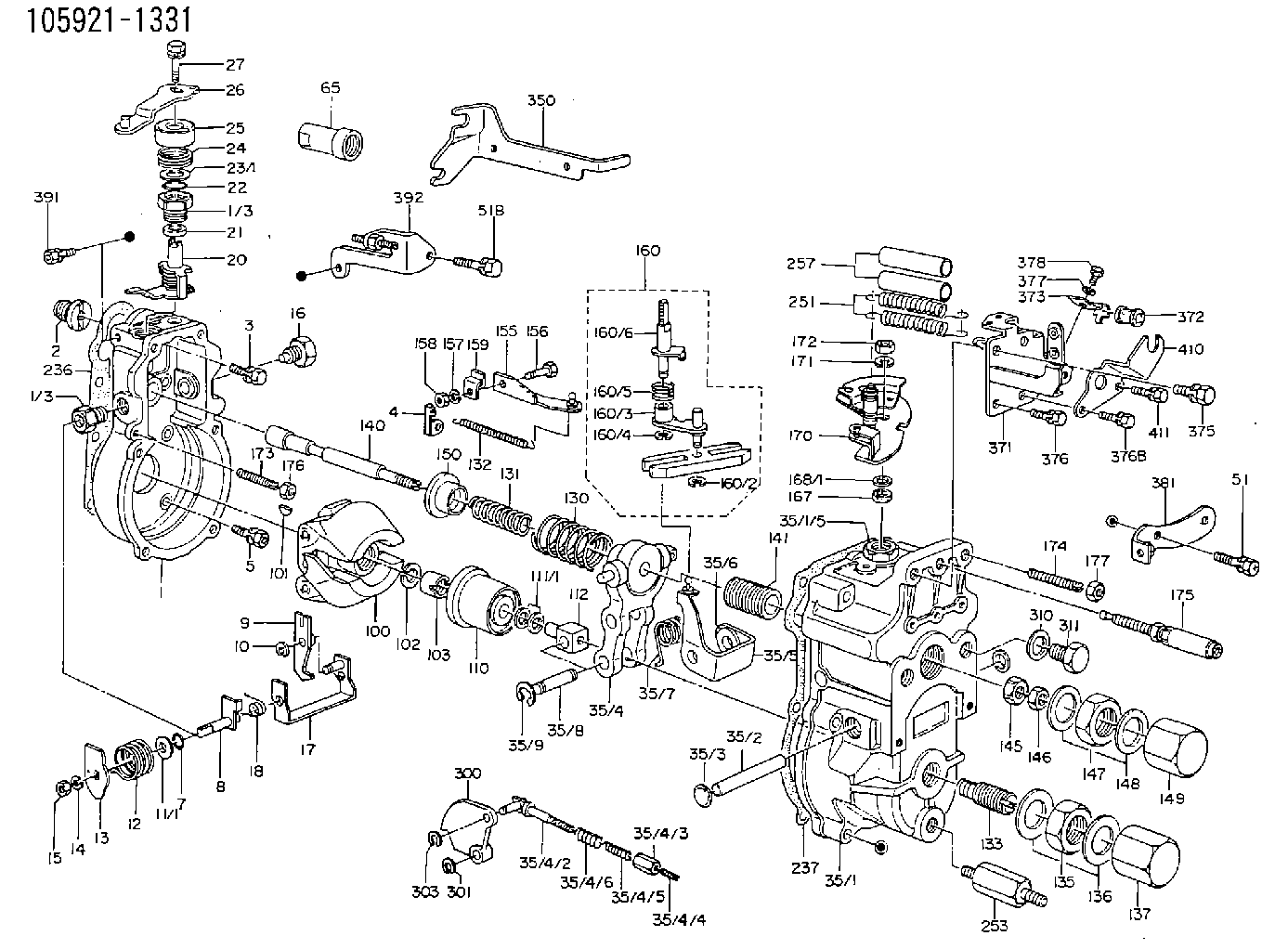
| 1. | [1] | 159200-2220 | GOVERNOR HOUSING |
| 1/3. | [2] | 154321-0400 | BUSHING |
| 1/3. | [2] | 154321-0400 | BUSHING |
| 2. | [1] | 154007-0200 | ADAPTOR |
| 3. | [1] | 020018-1840 | BLEEDER SCREW M8P1.25L18 |
| 4. | [1] | 159232-0401 | PLATE |
| 5. | [5] | 029010-6810 | BLEEDER SCREW |
| 5B. | [1] | 020106-1640 | BLEEDER SCREW M6P1.0L14 |
| 7. | [1] | 029631-0030 | O-RING &9.8W2.3 |
| 8. | [1] | 159205-2821 | LEVER SHAFT |
| 9. | [1] | 159202-1301 | CONTROL LEVER |
| 10. | [1] | 016010-0810 | LOCKING WASHER |
| 11/1. | [0] | 029311-0520 | SHIM D20.8&10.3T0.2 |
| 11/1. | [0] | 029311-0530 | SHIM D20.8&10.3T0.25 |
| 11/1. | [0] | 029311-0540 | SHIM D20.8&10.3T0.3 |
| 11/1. | [0] | 029311-0550 | SHIM D20.8&10.3T0.35 |
| 11/1. | [0] | 029311-0560 | SHIM D20.8&10.3T0.4 |
| 11/1. | [0] | 029311-0570 | SHIM D20.8&10.3T0.5 |
| 12. | [1] | 159215-0500 | COILED SPRING |
| 13. | [1] | 159242-0100 | CONTROL LEVER |
| 14. | [1] | 014110-8440 | LOCKING WASHER |
| 15. | [1] | 013020-8040 | UNION NUT M8P1.25H7 |
| 16. | [1] | 159237-0000 | CAPSULE |
| 17. | [1] | 159202-0720 | CONTROL LEVER |
| 18. | [1] | 159215-0600 | COILED SPRING |
| 20. | [1] | 159242-0920 | CONTROL LEVER |
| 21. | [1] | 159242-0600 | BUSHING |
| 22. | [1] | 029631-0030 | O-RING &9.8W2.3 |
| 23/1. | [0] | 029311-0520 | SHIM D20.8&10.3T0.2 |
| 23/1. | [0] | 029311-0530 | SHIM D20.8&10.3T0.25 |
| 23/1. | [0] | 029311-0540 | SHIM D20.8&10.3T0.3 |
| 23/1. | [0] | 029311-0550 | SHIM D20.8&10.3T0.35 |
| 23/1. | [0] | 029311-0560 | SHIM D20.8&10.3T0.4 |
| 23/1. | [0] | 029311-0570 | SHIM D20.8&10.3T0.5 |
| 24. | [1] | 159215-0500 | COILED SPRING |
| 25. | [1] | 154322-0100 | CAP |
| 26. | [1] | 159249-1220 | CONTROL LEVER |
| 27. | [1] | 020006-1640 | BLEEDER SCREW M6P1L16 4T |
| 35. | [1] | 159251-3420 | GOVERNOR COVER |
| 35/1. | [1] | 159201-3120 | GOVERNOR COVER |
| 35/2. | [1] | 159205-0400 | LEVER SHAFT |
| 35/3. | [2] | 159237-0200 | CAPSULE |
| 35/4. | [1] | 159253-0520 | TENSIONING LEVER |
| 35/4/1. | [1] | 159203-0620 | TENSIONING LEVER |
| 35/4/2. | [1] | 159204-5021 | RACK |
| 35/4/3. | [1] | 159233-0300 | UNION NUT |
| 35/4/4. | [1] | 159234-0000 | FLAT-HEAD SCREW |
| 35/4/5. | [1] | 159216-0000 | COILED SPRING |
| 35/4/6. | [1] | 159216-0100 | COILED SPRING |
| 35/5. | [1] | 159203-5120 | GUIDE LEVER |
| 35/6. | [2] | 159235-5000 | BUSHING |
| 35/7. | [1] | 159215-0201 | COILED SPRING |
| 35/8. | [1] | 159231-0800 | BEARING PIN |
| 35/9. | [2] | 016010-0610 | LOCKING WASHER |
| 51. | [5] | 020106-3840 | BLEEDER SCREW |
| 51B. | [2] | 020106-4540 | BLEEDER SCREW M6P1.0L45 |
| 65. | [1] | 154050-1720 | STOPPING DEVICE |
| 100. | [1] | 154101-0420 | FLYWEIGHT ASSEMBLY |
| 101. | [1] | 025803-1610 | WOODRUFF KEY |
| 102. | [1] | 029321-2020 | LOCKING WASHER |
| 103. | [1] | 029231-2030 | UNION NUT |
| 110. | [1] | 154123-1020 | SLIDING PIECE |
| 111/1. | [0] | 029311-0010 | SHIM D14&10.1T0.2 |
| 111/1. | [0] | 029311-0180 | SHIM D14&10.1T0.3 |
| 111/1. | [0] | 029311-0190 | SHIM D14&10.1T0.40 |
| 111/1. | [0] | 029311-0210 | SHIM D14&10.1T1 |
| 111/1. | [0] | 139410-0000 | SHIM D14.0&10.1T0.5 |
| 111/1. | [0] | 139410-0100 | SHIM D14.0&10.1T1.5 |
| 111/1. | [0] | 139410-3000 | SHIM D14&10.1T2.0 |
| 111/1. | [0] | 139410-3100 | SHIM D14&10.1T3.0 |
| 111/1. | [0] | 139410-3200 | SHIM D14&10.1T4.0 |
| 112. | [1] | 159236-0100 | TERMINAL STUD |
| 130. | [1] | 159210-1300 | GOVERNOR SPRING |
| 131. | [1] | 159211-2500 | GOVERNOR SPRING |
| 132. | [1] | 159214-0100 | COILED SPRING |
| 133. | [1] | 159212-1220 | HEADLESS SCREW |
| 135. | [1] | 139220-0200 | UNION NUT |
| 136. | [2] | 026520-2440 | GASKET D23.9&20.2T1 |
| 137. | [1] | 159248-0700 | CAP |
| 140. | [1] | 159205-0301 | LEVER SHAFT |
| 141. | [1] | 159234-5200 | GUIDE SLEEVE |
| 145. | [1] | 159233-5000 | UNION NUT |
| 146. | [1] | 023020-8040 | UNION NUT M8P1H5 |
| 147. | [1] | 139222-0200 | UNION NUT |
| 148. | [2] | 026522-2740 | GASKET D26.9&22.2T1 |
| 149. | [1] | 159237-5000 | CAP |
| 150. | [1] | 159235-5300 | SLOTTED WASHER |
| 155. | [1] | 159204-0220 | STRAP |
| 156. | [1] | 159237-0300 | BLEEDER SCREW |
| 157. | [1] | 014110-5440 | LOCKING WASHER |
| 158. | [1] | 159233-5620 | UNION NUT |
| 159. | [1] | 159242-1300 | PLATE |
| 160. | [1] | 159252-0022 | LEVER GROUP |
| 160/1. | [1] | 159202-2200 | CONTROL LEVER |
| 160/1. | [1] | 159202-2200 | CONTROL LEVER |
| 160/2. | [1] | 016010-0810 | LOCKING WASHER |
| 160/3. | [1] | 159202-0820 | CONTROL LEVER |
| 160/4. | [1] | 016010-0810 | LOCKING WASHER |
| 160/5. | [1] | 159215-0700 | COILED SPRING |
| 160/6. | [1] | 159205-0721 | LEVER SHAFT |
| 167. | [1] | 029621-0080 | PACKING RING |
| 168/1. | [0] | 029311-0640 | SHIM D26.0&10.2T0.95 |
| 168/1. | [0] | 029311-0650 | SHIM D26.0&10.2T0.20 |
| 168/1. | [0] | 029311-0660 | SHIM D26.0&10.2T0.25 |
| 168/1. | [0] | 029311-0670 | SHIM D26.0&10.2T0.30 |
| 168/1. | [0] | 029311-0680 | SHIM D26.0&10.2T0.35 |
| 168/1. | [0] | 029311-0690 | SHIM D26.0&10.2T0.40 |
| 168/1. | [0] | 029311-0700 | SHIM D26.0&10.2T0.50 |
| 168/1. | [0] | 139410-1400 | SHIM D26&10.2T0.7 |
| 168/1. | [0] | 139410-1500 | SHIM D26&10.2T0.9 |
| 168/1. | [0] | 139410-1600 | SHIM D26&10.2T0.8 |
| 168/1. | [0] | 139410-2700 | SHIM D26&10.2T0.6 |
| 169. | [1] | 139410-2300 | SHIM |
| 170. | [1] | 159244-4120 | CONTROL LEVER |
| 171. | [1] | 014110-8440 | LOCKING WASHER |
| 172. | [1] | 013020-8040 | UNION NUT M8P1.25H7 |
| 173. | [1] | 155615-1100 | FLAT-HEAD SCREW M6P1.0L37 |
| 174. | [1] | 154010-0100 | FLAT-HEAD SCREW |
| 175. | [1] | 159226-2721 | THERMOSTAT |
| 176. | [1] | 029240-6010 | UNION NUT M6P1.0H5* |
| 177. | [1] | 154011-0100 | HEXAGON NUT |
| 236. | [1] | 154390-0000 | GASKET |
| 237. | [1] | 159238-3100 | GASKET |
| 251. | [2] | 159243-8300 | COILED SPRING |
| 253. | [1] | 159248-2200 | BLEEDER SCREW |
| 257. | [2] | 154156-1800 | TUBE |
| 300. | [1] | 159207-1900 | CAM PLATE |
| 301. | [1] | 016010-0840 | LOCKING WASHER |
| 303. | [1] | 016010-0540 | LOCKING WASHER |
| 310. | [1] | 026516-2040 | GASKET D19.9&16.2T1 |
| 311. | [1] | 159237-0100 | CAPSULE |
| 350. | [1] | 159226-7600 | BRACKET |
| 371. | [1] | 159227-1120 | BRACKET |
| 372. | [1] | 159225-1200 | BUSHING |
| 373. | [1] | 159226-3400 | PLATE |
| 375. | [1] | 020118-1640 | BLEEDER SCREW |
| 376. | [1] | 020106-1240 | BLEEDER SCREW M6P1.0L12 |
| 376B. | [1] | 020106-1640 | BLEEDER SCREW M6P1.0L14 |
| 377. | [1] | 014010-5140 | PLAIN WASHER D12&5.5T0.8 |
| 378. | [1] | 020105-1640 | BLEEDER SCREW M5P0.8L16 |
| 381. | [1] | 159225-0620 | BRACKET |
| 391. | [1] | 020106-1040 | BLEEDER SCREW M6P1L12 |
| 392. | [1] | 159226-5420 | BRACKET |
| 410. | [1] | 159226-2900 | BRACKET |
| 411. | [1] | 020106-1040 | BLEEDER SCREW M6P1L12 |
Include in #1:
101491-9211
as GOVERNOR
Cross reference number
Zexel num
Bosch num
Firm num
Name
105921-1331
F 019 Z1E 694
GOVERNOR
* K
* K
Information:
Start By:a. remove oil panb. remove underframe 1. Remove bolts (1) that hold main bearing cap (2) in place and remove main cap (2).2. Remove the bearing half from the cap.
If the crankshaft is turned in the wrong direction, the tab of the bearing will be pushed between the crankshaft and cylinder block. This can cause damage to either or both the crankshaft and block.
3. Remove the upper half of main bearings (3) as follows:a. Turn the crankshaft until tool (A) can be installed in the crankshaft journal. Install tool (A).b. Turn the crankshaft in the direction which will push the upper main bearing out, tab end first.c. Check the condition of the bearings. (See Guideline For Reusable Parts, Main And Connecting Rod Bearings, Form No. SEBF8009 and SEBD0531). The following steps are for the installation of the crankshaft main bearings. Put clean engine oil on the main bearings for the assembly. Also, be sure the tabs on the back side of the main bearings fit in the grooves of the main bearing caps and cylinder block.4. Clean the surfaces in the cylinder block for the main bearings. Use tool (A), and install new upper halves of main bearing (bearings with the oil hole) in the cylinder block. Do not put oil on the back of the bearing.5. Clean the surface of the main bearing caps for the main bearings. Install the new lower halves of the main bearings in the main caps. Do not put oil on the back of the bearing. Main bearing caps should be installed with the part number towards the right side. Caps are to be identified by stamped numbers 1 thru 7 located on the bottom unmachined surface.6. Put main bearing caps (2) in position on the cylinder block. Put engine oil or molylube on the bolt threads and the washer face, then install the bolts. Tighten the bolts on the side where the main bearing tabs are located to a torque of 95 5 N m (70 4 lb.ft.). Tighten the bolts on the opposite side to a torque of 95 5 N m (70 4 lb.ft.).7. Put a mark on each bolt head and the bearing caps. Turn the bolts that are opposite the main bearing tabs an additional 90° 5° turn. Then turn the bolts on the side where the main bearing tabs are located an additional 90° 5° turn.
Typical Example8. Check the end play of the crankshaft with a dial indicator and magnetic base. The end play must be 0.1 to 0.5 mm (.004 to .020 in.). The end play is controlled by thrust bearings (4), which are located at the center main.End By:a. install underframeb. install oil pan
Have questions with 105921-1331?
Group cross 105921-1331 ZEXEL
Nissan-Diesel
Hino
105921-1331
F 019 Z1E 694
GOVERNOR