Information governor
BOSCH
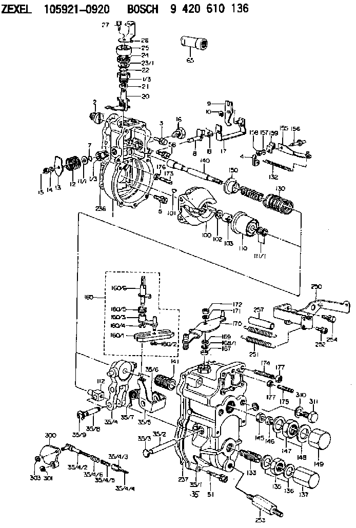
9 420 610 136
9420610136
ZEXEL
105921-0920
1059210920
NISSAN-DIESEL
19200L9205
19200l9205
Rating:
Scheme ###:
| 1. | [1] | 159200-1120 | GOVERNOR HOUSING |
| 1/3. | [2] | 154321-0400 | BUSHING |
| 1/3. | [2] | 154321-0400 | BUSHING |
| 2. | [1] | 154007-0200 | ADAPTOR |
| 3. | [1] | 020018-1840 | BLEEDER SCREW M8P1.25L18 |
| 4. | [1] | 159232-0401 | PLATE |
| 5. | [5] | 029010-6810 | BLEEDER SCREW |
| 5B. | [1] | 020106-1640 | BLEEDER SCREW M6P1.0L14 |
| 7. | [1] | 029631-0030 | O-RING &9.8W2.3 |
| 8. | [1] | 159205-2821 | LEVER SHAFT |
| 9. | [1] | 159202-0600 | CONTROL LEVER |
| 10. | [1] | 016010-0810 | LOCKING WASHER |
| 11/1. | [0] | 029311-0520 | SHIM D20.8&10.3T0.2 |
| 11/1. | [0] | 029311-0530 | SHIM D20.8&10.3T0.25 |
| 11/1. | [0] | 029311-0540 | SHIM D20.8&10.3T0.3 |
| 11/1. | [0] | 029311-0550 | SHIM D20.8&10.3T0.35 |
| 11/1. | [0] | 029311-0560 | SHIM D20.8&10.3T0.4 |
| 11/1. | [0] | 029311-0570 | SHIM D20.8&10.3T0.5 |
| 12. | [1] | 159215-0500 | COILED SPRING |
| 13. | [1] | 159242-0100 | CONTROL LEVER |
| 14. | [1] | 014110-8440 | LOCKING WASHER |
| 15. | [1] | 013020-8040 | UNION NUT M8P1.25H7 |
| 16. | [1] | 159237-0000 | CAPSULE |
| 17. | [1] | 159202-0720 | CONTROL LEVER |
| 18. | [1] | 159215-0600 | COILED SPRING |
| 20. | [1] | 159242-0920 | CONTROL LEVER |
| 21. | [1] | 159242-0600 | BUSHING |
| 22. | [1] | 029631-0030 | O-RING &9.8W2.3 |
| 23/1. | [0] | 029311-0520 | SHIM D20.8&10.3T0.2 |
| 23/1. | [0] | 029311-0530 | SHIM D20.8&10.3T0.25 |
| 23/1. | [0] | 029311-0540 | SHIM D20.8&10.3T0.3 |
| 23/1. | [0] | 029311-0550 | SHIM D20.8&10.3T0.35 |
| 23/1. | [0] | 029311-0560 | SHIM D20.8&10.3T0.4 |
| 23/1. | [0] | 029311-0570 | SHIM D20.8&10.3T0.5 |
| 24. | [1] | 159215-0500 | COILED SPRING |
| 25. | [1] | 154322-0100 | CAP |
| 26. | [1] | 159242-4300 | CONTROL LEVER |
| 27. | [1] | 020006-1640 | BLEEDER SCREW M6P1L16 4T |
| 35. | [1] | 159251-3720 | GOVERNOR COVER |
| 35/1. | [1] | 159201-2220 | GOVERNOR COVER |
| 35/2. | [1] | 159205-0400 | LEVER SHAFT |
| 35/3. | [2] | 159237-0200 | CAPSULE |
| 35/4. | [1] | 159253-0520 | TENSIONING LEVER |
| 35/4/1. | [1] | 159203-0620 | TENSIONING LEVER |
| 35/4/2. | [1] | 159204-5021 | RACK |
| 35/4/3. | [1] | 159233-0300 | UNION NUT |
| 35/4/4. | [1] | 159234-0000 | FLAT-HEAD SCREW |
| 35/4/5. | [1] | 159216-0000 | COILED SPRING |
| 35/4/6. | [1] | 159216-0100 | COILED SPRING |
| 35/5. | [1] | 159203-5120 | GUIDE LEVER |
| 35/6. | [2] | 159235-5000 | BUSHING |
| 35/7. | [1] | 159215-0201 | COILED SPRING |
| 35/8. | [1] | 159231-0800 | BEARING PIN |
| 35/9. | [2] | 016010-0610 | LOCKING WASHER |
| 51. | [7] | 020106-3840 | BLEEDER SCREW |
| 65. | [1] | 154050-1720 | STOPPING DEVICE |
| 100. | [1] | 154100-9520 | FLYWEIGHT ASSEMBLY |
| 101. | [1] | 025803-1610 | WOODRUFF KEY |
| 102. | [1] | 029321-2020 | LOCKING WASHER |
| 103. | [1] | 029231-2030 | UNION NUT |
| 110. | [1] | 154123-1020 | SLIDING PIECE |
| 111/1. | [0] | 029311-0010 | SHIM D14&10.1T0.2 |
| 111/1. | [0] | 029311-0180 | SHIM D14&10.1T0.3 |
| 111/1. | [0] | 029311-0190 | SHIM D14&10.1T0.40 |
| 111/1. | [0] | 029311-0210 | SHIM D14&10.1T1 |
| 111/1. | [0] | 139410-0000 | SHIM D14.0&10.1T0.5 |
| 111/1. | [0] | 139410-0100 | SHIM D14.0&10.1T1.5 |
| 111/1. | [0] | 139410-3000 | SHIM D14&10.1T2.0 |
| 111/1. | [0] | 139410-3100 | SHIM D14&10.1T3.0 |
| 111/1. | [0] | 139410-3200 | SHIM D14&10.1T4.0 |
| 112. | [1] | 159236-0100 | TERMINAL STUD |
| 130. | [1] | 159210-3100 | GOVERNOR SPRING |
| 132. | [1] | 159214-0000 | COILED SPRING |
| 133. | [1] | 159212-1720 | HEADLESS SCREW |
| 135. | [1] | 139220-0200 | UNION NUT |
| 136. | [2] | 026520-2440 | GASKET D23.9&20.2T1 |
| 137. | [1] | 159248-0700 | CAP |
| 140. | [1] | 159205-0301 | LEVER SHAFT |
| 141. | [1] | 159234-5200 | GUIDE SLEEVE |
| 145. | [1] | 159233-5000 | UNION NUT |
| 146. | [1] | 023020-8040 | UNION NUT M8P1H5 |
| 147. | [1] | 139222-0200 | UNION NUT |
| 148. | [2] | 026522-2740 | GASKET D26.9&22.2T1 |
| 149. | [1] | 159237-5000 | CAP |
| 150. | [1] | 159235-5300 | SLOTTED WASHER |
| 155. | [1] | 159204-0220 | STRAP |
| 156. | [1] | 159237-0300 | BLEEDER SCREW |
| 157. | [1] | 014110-5440 | LOCKING WASHER |
| 158. | [1] | 159233-5200 | UNION NUT |
| 159. | [1] | 159242-1300 | PLATE |
| 160. | [1] | 159252-0022 | LEVER GROUP |
| 160/1. | [1] | 159202-2200 | CONTROL LEVER |
| 160/2. | [1] | 016010-0810 | LOCKING WASHER |
| 160/3. | [1] | 159202-0820 | CONTROL LEVER |
| 160/4. | [1] | 016010-0810 | LOCKING WASHER |
| 160/5. | [1] | 159215-0700 | COILED SPRING |
| 160/6. | [1] | 159205-0721 | LEVER SHAFT |
| 167. | [1] | 029621-0080 | PACKING RING |
| 168/1. | [0] | 029311-0640 | SHIM D26.0&10.2T0.95 |
| 168/1. | [0] | 029311-0650 | SHIM D26.0&10.2T0.20 |
| 168/1. | [0] | 029311-0660 | SHIM D26.0&10.2T0.25 |
| 168/1. | [0] | 029311-0670 | SHIM D26.0&10.2T0.30 |
| 168/1. | [0] | 029311-0680 | SHIM D26.0&10.2T0.35 |
| 168/1. | [0] | 029311-0690 | SHIM D26.0&10.2T0.40 |
| 168/1. | [0] | 029311-0700 | SHIM D26.0&10.2T0.50 |
| 168/1. | [0] | 139410-1400 | SHIM D26&10.2T0.7 |
| 168/1. | [0] | 139410-1500 | SHIM D26&10.2T0.9 |
| 168/1. | [0] | 139410-1600 | SHIM D26&10.2T0.8 |
| 168/1. | [0] | 139410-2700 | SHIM D26&10.2T0.6 |
| 169. | [1] | 139410-2300 | SHIM |
| 170. | [1] | 159241-2520 | CONTROL LEVER |
| 171. | [1] | 014110-8440 | LOCKING WASHER |
| 172. | [1] | 013020-8040 | UNION NUT M8P1.25H7 |
| 173. | [1] | 155615-1100 | FLAT-HEAD SCREW M6P1.0L37 |
| 174. | [1] | 154010-0100 | FLAT-HEAD SCREW |
| 175. | [1] | 154010-0100 | FLAT-HEAD SCREW |
| 176. | [1] | 029240-6010 | UNION NUT M6P1.0H5* |
| 177. | [2] | 154011-0100 | HEXAGON NUT |
| 177. | [2] | 154011-0100 | HEXAGON NUT |
| 236. | [1] | 154390-0000 | GASKET |
| 237. | [1] | 159238-3100 | GASKET |
| 250. | [1] | 159245-6220 | BRACKET |
| 251. | [2] | 159243-1000 | COILED SPRING |
| 252. | [3] | 020106-1040 | BLEEDER SCREW M6P1L12 |
| 253. | [1] | 159248-1700 | BLEEDER SCREW |
| 254. | [1] | 020018-1640 | BLEEDER SCREW M8P1.25L16 4T |
| 257. | [2] | 154156-0500 | TUBE |
| 300. | [1] | 159207-2000 | CAM PLATE |
| 301. | [1] | 016010-0840 | LOCKING WASHER |
| 303. | [1] | 016010-0540 | LOCKING WASHER |
| 310. | [1] | 026516-2040 | GASKET D19.9&16.2T1 |
| 311. | [1] | 159237-0100 | CAPSULE |
Include in #1:
101602-9501
as GOVERNOR
Cross reference number
Zexel num
Bosch num
Firm num
Name
105921-0920
19200L9205 NISSAN-DIESEL
GOVERNOR
K 14JK MECHANICAL GOVERNOR GOV RLD GOV
K 14JK MECHANICAL GOVERNOR GOV RLD GOV
Information:
Make reference to Guideline For Reusable Parts; Pistons, Form No. SEBF8049; Cylinder Liners, Form No. SEBF8068; and Piston Pins And Retaining Rings, Form No. SEBF8051. For installation, number on tab groove side of connecting rod is to be positioned toward opposite side of engine from camshaft.Top And Intermediate Ring
The 8T3150 Keystone Piston Ring Groove Gauge is necessary for measuring ring groove in keystone style pistons. For correct use of the gauge group, see the instruction card that is with the gauge group.Install piston rings with "UP" side toward top of piston.(1) Top Ring has the mark "UP-1."(2) Intermediate ring has the mark "UP-2".Clearance between ends of piston ring when installed in a cylinder liner with a bore size of 137.16 mm (5.400 in)Top ring ... 0.724 0.191 mm (.0285 .0075 in)Intermediate ring ... 1.080 0.190 mm (.0425 .0075 in)Increase in clearance between ends of piston rings for each 0.03 mm (.001 in) increase in cylinder liner bore size ... 0.08 mm (.003 in)Oil Control Ring
(3) Install oil control ring with the gap in the spring 180° away from the gap in the ring. White portion of spring must be visible at the ring end gap.Width of groove in piston for piston ring (new) ... 3.210 0.010 mm (.1264 .0004 in)Thickness of piston ring (new) ... 3.137 0.013 mm (.1235 .0005 in)Clearance between groove and piston ring (new) ... 0.073 0.023 mm (.0029 .0009 in)Maximum permissible clearance (worn) ... 0.15 mm (.006 in)Clearance between ends of piston ring when installed in a cylinder liner with a bore size of 137.16 mm (5.400 in) ... 0.572 0.191 mm (.0225 .0075 in)Increase in clearance between ends of piston ring for each 0.03 mm (.001 in) increase in cylinder liner bore size ... 0.08 mm (.003 in)Piston Pin Bore
(4) Bore in piston for pin. 1991 Model with elliptical pin bore (310 - 425 hp) Vertical ... 50.814 0.004 mm (2.0005 .0001 in)Horizontal ... actual vertical diameter plus 0.032 to 0.048 mm (.0012 to .0019 in)Clearance between pin and bore in piston ... 0.010 to 0.028 mm (.0004 to .0011 in)Permissible clearance (worn) ... 0.05 mm (.002 in)Pin diameter ... 50.795 0.005 mm (1.9998 .0002 in) Low Crevice Volume and Gallery Pistons Bore in piston for pin ... 50.814 0.004 mm (2.0005 .0001 in)Clearance between pin and bore in piston ... 0.010 to 0.028 mm (.0004 to .0011 in)Permissible clearance (worn) ... 0.05 mm (.002 in)Pin diameter ... 50.795 0.005 mm (1.9998 .0002 in)All Other Pistons Bore in piston for pin ... 50.815 0.008 mm (2.0006 .0003 in)Clearance between pin and bore in piston ... 0.007 to 0.032 mm (.0003 to .0013 in)Permissible clearance (worn) ... 0.05 mm (.002 in)Pin diameter ... 50.795 0.005 mm (1.9998 .0002 in)