Information governor
BOSCH
F 019 Z1E 691
f019z1e691
ZEXEL
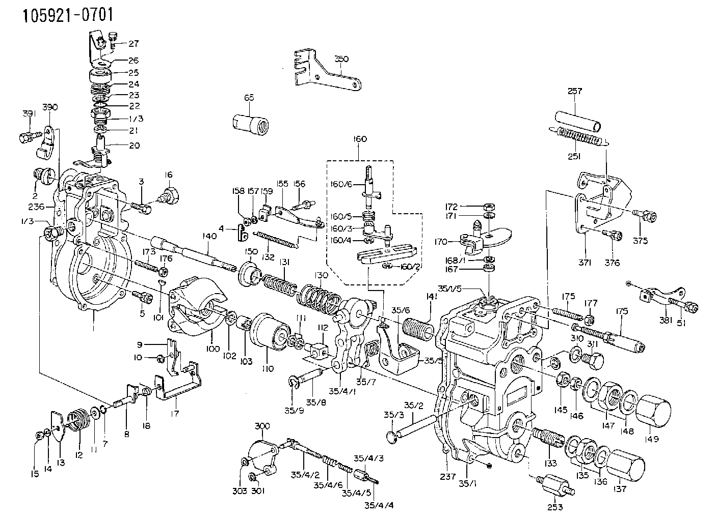
105921-0701
1059210701
MAZDA
SL0313VL0
sl0313vl0
Rating:
Scheme ###:
| 1. | [1] | 159200-2220 | GOVERNOR HOUSING |
| 1/3. | [2] | 154321-0400 | BUSHING |
| 1/3. | [2] | 154321-0400 | BUSHING |
| 2. | [1] | 154007-0200 | ADAPTOR |
| 3. | [1] | 020018-1840 | BLEEDER SCREW M8P1.25L18 |
| 4. | [1] | 159232-0401 | PLATE |
| 5. | [5] | 029010-6810 | BLEEDER SCREW |
| 5B. | [1] | 020106-1640 | BLEEDER SCREW M6P1.0L14 |
| 7. | [1] | 029631-0030 | O-RING &9.8W2.3 |
| 8. | [1] | 159205-2821 | LEVER SHAFT |
| 9. | [1] | 159202-1301 | CONTROL LEVER |
| 10. | [1] | 016010-0810 | LOCKING WASHER |
| 11/1. | [0] | 029311-0520 | SHIM D20.8&10.3T0.2 |
| 11/1. | [0] | 029311-0530 | SHIM D20.8&10.3T0.25 |
| 11/1. | [0] | 029311-0540 | SHIM D20.8&10.3T0.3 |
| 11/1. | [0] | 029311-0550 | SHIM D20.8&10.3T0.35 |
| 11/1. | [0] | 029311-0560 | SHIM D20.8&10.3T0.4 |
| 11/1. | [0] | 029311-0570 | SHIM D20.8&10.3T0.5 |
| 12. | [1] | 159215-0500 | COILED SPRING |
| 13. | [1] | 159242-0100 | CONTROL LEVER |
| 14. | [1] | 014110-8440 | LOCKING WASHER |
| 15. | [1] | 013020-8040 | UNION NUT M8P1.25H7 |
| 16. | [1] | 159237-0000 | CAPSULE |
| 17. | [1] | 159202-0720 | CONTROL LEVER |
| 18. | [1] | 159215-0600 | COILED SPRING |
| 20. | [1] | 159242-0920 | CONTROL LEVER |
| 21. | [1] | 159242-0600 | BUSHING |
| 22. | [1] | 029631-0030 | O-RING &9.8W2.3 |
| 23/1. | [0] | 029311-0520 | SHIM D20.8&10.3T0.2 |
| 23/1. | [0] | 029311-0530 | SHIM D20.8&10.3T0.25 |
| 23/1. | [0] | 029311-0540 | SHIM D20.8&10.3T0.3 |
| 23/1. | [0] | 029311-0550 | SHIM D20.8&10.3T0.35 |
| 23/1. | [0] | 029311-0560 | SHIM D20.8&10.3T0.4 |
| 23/1. | [0] | 029311-0570 | SHIM D20.8&10.3T0.5 |
| 24. | [1] | 159215-0500 | COILED SPRING |
| 25. | [1] | 154322-0100 | CAP |
| 26. | [1] | 159242-5520 | CONTROL LEVER |
| 27. | [1] | 020006-1640 | BLEEDER SCREW M6P1L16 4T |
| 35. | [1] | 159251-3420 | GOVERNOR COVER |
| 35/1. | [1] | 159201-3120 | GOVERNOR COVER |
| 35/2. | [1] | 159205-0400 | LEVER SHAFT |
| 35/3. | [2] | 159237-0200 | CAPSULE |
| 35/4. | [1] | 159253-0520 | TENSIONING LEVER |
| 35/4/1. | [1] | 159203-0620 | TENSIONING LEVER |
| 35/4/2. | [1] | 159204-5021 | RACK |
| 35/4/3. | [1] | 159233-0300 | UNION NUT |
| 35/4/4. | [1] | 159234-0000 | FLAT-HEAD SCREW |
| 35/4/5. | [1] | 159216-0000 | COILED SPRING |
| 35/4/6. | [1] | 159216-0100 | COILED SPRING |
| 35/5. | [1] | 159203-5120 | GUIDE LEVER |
| 35/6. | [2] | 159235-5000 | BUSHING |
| 35/7. | [1] | 159215-0201 | COILED SPRING |
| 35/8. | [1] | 159231-0800 | BEARING PIN |
| 35/9. | [2] | 016010-0610 | LOCKING WASHER |
| 51. | [7] | 020106-3840 | BLEEDER SCREW |
| 65. | [1] | 155404-1500 | CAP |
| 100. | [1] | 154101-0420 | FLYWEIGHT ASSEMBLY |
| 101. | [1] | 025803-1610 | WOODRUFF KEY |
| 102. | [1] | 029321-2020 | LOCKING WASHER |
| 103. | [1] | 029231-2030 | UNION NUT |
| 110. | [1] | 154123-1020 | SLIDING PIECE |
| 111/1. | [0] | 029311-0010 | SHIM D14&10.1T0.2 |
| 111/1. | [0] | 029311-0180 | SHIM D14&10.1T0.3 |
| 111/1. | [0] | 029311-0190 | SHIM D14&10.1T0.40 |
| 111/1. | [0] | 029311-0210 | SHIM D14&10.1T1 |
| 111/1. | [0] | 139410-0000 | SHIM D14.0&10.1T0.5 |
| 111/1. | [0] | 139410-0100 | SHIM D14.0&10.1T1.5 |
| 111/1. | [0] | 139410-3000 | SHIM D14&10.1T2.0 |
| 111/1. | [0] | 139410-3100 | SHIM D14&10.1T3.0 |
| 111/1. | [0] | 139410-3200 | SHIM D14&10.1T4.0 |
| 112. | [1] | 159236-0100 | TERMINAL STUD |
| 130. | [1] | 159210-1300 | GOVERNOR SPRING |
| 131. | [1] | 159211-2500 | GOVERNOR SPRING |
| 132. | [1] | 159214-0100 | COILED SPRING |
| 133. | [1] | 159212-1220 | HEADLESS SCREW |
| 135. | [1] | 139220-0200 | UNION NUT |
| 136. | [2] | 026520-2440 | GASKET D23.9&20.2T1 |
| 137. | [1] | 159248-0700 | CAP |
| 140. | [1] | 159205-0301 | LEVER SHAFT |
| 141. | [1] | 159234-5200 | GUIDE SLEEVE |
| 145. | [1] | 159233-5000 | UNION NUT |
| 146. | [1] | 023020-8040 | UNION NUT M8P1H5 |
| 147. | [1] | 139222-0200 | UNION NUT |
| 148. | [2] | 026522-2740 | GASKET D26.9&22.2T1 |
| 149. | [1] | 159237-5000 | CAP |
| 150. | [1] | 159235-5300 | SLOTTED WASHER |
| 155. | [1] | 159204-0220 | STRAP |
| 156. | [1] | 159237-0300 | BLEEDER SCREW |
| 157. | [1] | 014110-5440 | LOCKING WASHER |
| 158. | [1] | 159233-5620 | UNION NUT |
| 159. | [1] | 159242-1300 | PLATE |
| 160. | [1] | 159252-0022 | LEVER GROUP |
| 160/1. | [1] | 159202-2200 | CONTROL LEVER |
| 160/1. | [1] | 159202-2200 | CONTROL LEVER |
| 160/2. | [1] | 016010-0810 | LOCKING WASHER |
| 160/3. | [1] | 159202-0820 | CONTROL LEVER |
| 160/4. | [1] | 016010-0810 | LOCKING WASHER |
| 160/5. | [1] | 159215-0700 | COILED SPRING |
| 160/6. | [1] | 159205-0721 | LEVER SHAFT |
| 167. | [1] | 029621-0080 | PACKING RING |
| 168/1. | [0] | 029311-0640 | SHIM D26.0&10.2T0.95 |
| 168/1. | [0] | 029311-0650 | SHIM D26.0&10.2T0.20 |
| 168/1. | [0] | 029311-0660 | SHIM D26.0&10.2T0.25 |
| 168/1. | [0] | 029311-0670 | SHIM D26.0&10.2T0.30 |
| 168/1. | [0] | 029311-0680 | SHIM D26.0&10.2T0.35 |
| 168/1. | [0] | 029311-0690 | SHIM D26.0&10.2T0.40 |
| 168/1. | [0] | 029311-0700 | SHIM D26.0&10.2T0.50 |
| 168/1. | [0] | 139410-1400 | SHIM D26&10.2T0.7 |
| 168/1. | [0] | 139410-1500 | SHIM D26&10.2T0.9 |
| 168/1. | [0] | 139410-1600 | SHIM D26&10.2T0.8 |
| 168/1. | [0] | 139410-2700 | SHIM D26&10.2T0.6 |
| 169. | [1] | 139410-2300 | SHIM |
| 170. | [1] | 159241-6120 | CONTROL LEVER |
| 171. | [1] | 014110-8440 | LOCKING WASHER |
| 172. | [1] | 013020-8040 | UNION NUT M8P1.25H7 |
| 173. | [1] | 155615-1100 | FLAT-HEAD SCREW M6P1.0L37 |
| 174. | [1] | 154010-0100 | FLAT-HEAD SCREW |
| 175. | [1] | 159225-3221 | THERMOSTAT |
| 176. | [1] | 029240-6010 | UNION NUT M6P1.0H5* |
| 177. | [1] | 154011-0100 | HEXAGON NUT |
| 236. | [1] | 154390-0000 | GASKET |
| 237. | [1] | 159238-3100 | GASKET |
| 251. | [1] | 159243-4200 | COILED SPRING |
| 253. | [1] | 159248-2200 | BLEEDER SCREW |
| 257. | [1] | 154156-1800 | TUBE |
| 300. | [1] | 159207-1900 | CAM PLATE |
| 301. | [1] | 016010-0840 | LOCKING WASHER |
| 303. | [1] | 016010-0540 | LOCKING WASHER |
| 310. | [1] | 026516-2040 | GASKET D19.9&16.2T1 |
| 311. | [1] | 159237-0100 | CAPSULE |
| 350. | [1] | 159245-7500 | BRACKET |
| 371. | [1] | 159225-3320 | BRACKET |
| 375. | [1] | 020118-1640 | BLEEDER SCREW |
| 376. | [3] | 020106-1240 | BLEEDER SCREW M6P1.0L12 |
| 381. | [1] | 159225-0620 | BRACKET |
| 390. | [1] | 159225-3120 | PLATE |
| 391. | [1] | 020106-0840 | BLEEDER SCREW |
Cross reference number
Zexel num
Bosch num
Firm num
Name
105921-0701
F 019 Z1E 691
SL0313VL0 MAZDA
GOVERNOR
* K
* K
Information:
Connect the wiring harness to a voltage source of 12 VOLTS maximum with a negative ground only. Install the additive tank on the outside of the engine compartment.
Connect the wiring to 8L5000 Switch (1) so that the system can be activated with the starting motor switch in the OFF position. Keep the additive tank full when not in use. This will prevent damage to the system and components by corrosion when not used for long periods of time.Operation: Just before the engine is started, push the switch to activate the system; this will let the additive flow for approximately two minutes, through an orifice connected to the fuel supply line of the Sleeve Metering Fuel System. The fuel transfer pump then pulls the additive into the system along with the Diesel fuel. The system can be again activated if necessary. The engine can be started approximately three to four times per liter (fifteen to twenty times per gallon) of additive.Maintenance: Keep the additive tank full when not in use. This will prevent damage to the system and components by corrosion when not used for long periods of time. Install a new injection group filter (9N3778) at six month intervals or when the filter becomes plugged (full of foreign material) so additive will not flow through it. ADDITIVE RECOMMENDATION: Ethyl D112 Diesel Ignition Improver AVAILABLE SOURCE:U.S.A.
Ethyl Corporation
Distribution Service
Petroleum Chemical Division
451 Florida Boulevard
Baton Rouge, Lousiana 70801
CANADA
Ethyl Corporation of Canada, Ltd.
48 St. Clair Avenue West
Toronto, Ontario, Canada M4V1M7
Order Department
Ethyl D11-2 Diesel Ignition Improver is highly flammable; do not install the additive tank near a source of heat or sparks. If there is a leak in the tank or an accident causes a loss of additive, a fire could be the result.
1 - 9N3334 Tank Assembly2 - 1P4022 Fitting3 - 9N3778 Filter Assembly4 - 8L6557 Connector5 - 317224 Hose Assembly6 - 306984 Connector7 - 9L8791 Solenoid8 - 7W1539 Orifice9 - 8T2543 Tee10 - 5P5009 Reducer11 - 9N3828 Harness Assembly12 - 7G1018 Relay13 - 8L5000 Switch14 - 9N3335 Strap 533567 Bracket15 - 5P0733 Hose 200 (8.0")16 - 1P4278 Clamp17 - 7D1553 Clip18 - 8J1256 Clip19 - 4B1248 Screw 4B2051 Nut 4B4674 Washer20 - 3J7354 Seal21 - 1J9671 Seal1 Install items (12) and (13) inside the operator's compartment; fasten switch (13) on the dash and install relay (12) under the dash. Install additive tank (1) on the outside of the engine compartment in an acceptable location for easy access and away from any source of heat.2 Install 9N3620 Fuel Additive Injection Instruction Film on the dash next to 8L5000 Switch (13). Install 9N3621 CAUTION Film on tank (1) at a location that can be seen from the side of the vehicle.3 Install the remainder of the parts as shown in the above illustration. Fasten filter (3), and hoses (5) and (15) with the clips shown.4 Check the system for leaks after the installation is complete; use air at a maximum pressure of 70 to 105 kPa (10 to 15 psi).
Have questions with 105921-0701?
Group cross 105921-0701 ZEXEL
Mazda
105921-0701
F 019 Z1E 691
SL0313VL0
GOVERNOR