Information governor
BOSCH
F 019 Z1E 193
f019z1e193
ZEXEL
105542-6560
1055426560
ISUZU
5157100170
5157100170
Rating:
Scheme ###:
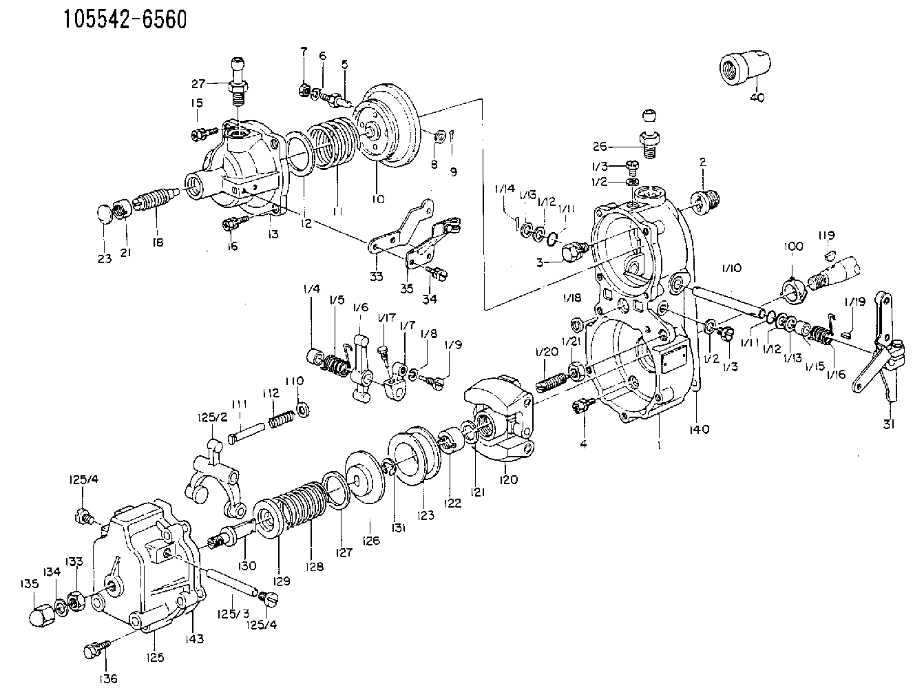
| 1. | [1] | 155014-7320 | GOVERNOR HOUSING |
| 1/1. | [1] | 155000-9110 | GOVERNOR HOUSING |
| 1/2. | [2] | 026506-1040 | GASKET D9.9&6.2T1 |
| 1/2. | [2] | 026506-1040 | GASKET D9.9&6.2T1 |
| 1/3. | [2] | 029010-6010 | CAPSULE M6P1.0L7 |
| 1/3. | [2] | 029010-6010 | CAPSULE M6P1.0L7 |
| 1/4. | [1] | 155052-7600 | BUSHING |
| 1/5. | [1] | 155005-0800 | COILED SPRING |
| 1/6. | [1] | 155003-1000 | CONTROL LEVER |
| 1/7. | [1] | 155003-1100 | CONTROL LEVER |
| 1/8. | [1] | 029320-6010 | LOCKING WASHER |
| 1/9. | [1] | 155411-8100 | FLAT-HEAD SCREW |
| 1/10. | [1] | 155004-2200 | LEVER SHAFT |
| 1/11. | [2] | 029630-8060 | O-RING |
| 1/11. | [2] | 029630-8060 | O-RING |
| 1/12. | [2] | 029300-8010 | PLAIN WASHER D15&8T1.00 |
| 1/12. | [2] | 029300-8010 | PLAIN WASHER D15&8T1.00 |
| 1/13. | [0] | 029310-8010 | PLAIN WASHER D15&8.4T0.2 |
| 1/13. | [0] | 029310-8010 | PLAIN WASHER D15&8.4T0.2 |
| 1/13. | [0] | 029310-8020 | PLAIN WASHER D15&8.4T0.3 |
| 1/14. | [1] | 025520-1210 | SPLIT PIN |
| 1/15. | [1] | 155052-7600 | BUSHING |
| 1/16. | [1] | 155005-0900 | COILED SPRING |
| 1/17. | [1] | 155006-0300 | BLEEDER SCREW |
| 1/18. | [1] | 029620-5010 | PACKING RING |
| 1/19. | [1] | 025802-1010 | WOODRUFF KEY |
| 1/20. | [1] | 155007-0520 | HEADLESS SCREW |
| 1/21. | [1] | 029241-0060 | UNION NUT |
| 2. | [1] | 154007-0200 | ADAPTOR |
| 3. | [1] | 020018-1840 | BLEEDER SCREW M8P1.25L18 |
| 4. | [4] | 029010-6810 | BLEEDER SCREW |
| 5. | [1] | 153406-0400 | BLEEDER SCREW |
| 6. | [1] | 014110-5440 | LOCKING WASHER |
| 7. | [1] | 013020-5240 | UNION NUT M5P0.8H4 |
| 8. | [1] | 023500-6210 | PLAIN WASHER D11&6.4T1.5 |
| 9. | [1] | 025520-1210 | SPLIT PIN |
| 10. | [1] | 155020-2120 | DIAPHRAGM |
| 11. | [1] | 155031-2600 | GOVERNOR SPRING |
| 12/1. | [0] | 155407-1100 | SHIM D37&30.5T0.5 |
| 12/1. | [0] | 155407-1200 | SHIM D37&30.5T1.0 |
| 12/1. | [0] | 155407-1300 | SHIM D37&30.5T1.5 |
| 12/1. | [0] | 155407-1400 | SHIM D37&30.5T2.0 |
| 12/1. | [0] | 155407-1500 | SHIM D37&30.5T2.5 |
| 12/1. | [0] | 155407-1600 | SHIM D37&30.5T3.0 |
| 12/1. | [0] | 155407-1700 | SHIM D37&30.5T0.2 |
| 12/1. | [0] | 155407-1800 | SHIM D37&30.5T0.3 |
| 13. | [1] | 155240-0500 | COVER |
| 15. | [3] | 020105-1640 | BLEEDER SCREW M5P0.8L16 |
| 16. | [1] | 029010-5350 | BLEEDER SCREW |
| 18. | [1] | 155241-2520 | HEADLESS SCREW |
| 21. | [1] | 155245-0100 | HEXAGON NUT |
| 23. | [1] | 029142-0010 | CAPSULE |
| 26. | [1] | 029721-2050 | JOINT CONNECTION |
| 27. | [1] | 155616-3020 | JOINT CONNECTION |
| 31. | [1] | 155400-6620 | CONTROL LEVER |
| 33. | [1] | 155402-2800 | PLATE |
| 34. | [2] | 029050-5040 | FLAT-HEAD SCREW M5P0.8L9 |
| 35. | [1] | 155418-0000 | CLAMPING BAND |
| 40. | [1] | 155404-0200 | CAP |
| 100. | [1] | 155412-5300 | IMPELLER WHEEL |
| 110. | [1] | 029300-5010 | PLAIN WASHER |
| 111/1. | [0] | 155411-0200 | STOP PIN L51 |
| 111/1. | [0] | 155411-0300 | STOP PIN L51.5 |
| 111/1. | [0] | 155411-0400 | STOP PIN L52 |
| 111/1. | [0] | 155411-7800 | STOP PIN L48.5 |
| 111/1. | [0] | 155411-7900 | STOP PIN L49.5 |
| 111/1. | [0] | 155411-8000 | STOP PIN L50.5 |
| 111/1. | [0] | 155411-9700 | STOP PIN L48 |
| 111/1. | [0] | 155411-9800 | STOP PIN L49 |
| 111/1. | [0] | 155411-9900 | STOP PIN L50 |
| 112. | [1] | 155411-8200 | COILED SPRING |
| 119. | [1] | 025803-1610 | WOODRUFF KEY |
| 120. | [1] | 154102-0620 | FLYWEIGHT ASSEMBLY |
| 121. | [1] | 029321-2020 | LOCKING WASHER |
| 122. | [1] | 029231-2030 | UNION NUT |
| 123. | [1] | 154123-0800 | SLIDING PIECE |
| 125. | [1] | 154405-4720 | COVER |
| 125/2. | [1] | 154406-2000 | FORK LINK |
| 125/3. | [1] | 154406-0500 | BEARING PIN |
| 125/4. | [2] | 029050-8050 | FLAT-HEAD SCREW |
| 125/4. | [2] | 029050-8050 | FLAT-HEAD SCREW |
| 126. | [1] | 154406-1700 | SLOTTED WASHER |
| 127. | [0] | 029302-3010 | SHIM D30&23T0.5 |
| 127B. | [0] | 029302-3020 | SHIM D30&23T1.0 |
| 128. | [1] | 155032-2500 | GOVERNOR SPRING |
| 128B. | [1] | 155031-9800 | GOVERNOR SPRING |
| 129. | [1] | 154406-1600 | SLOTTED WASHER |
| 130. | [1] | 154406-1000 | FLAT-HEAD SCREW |
| 131. | [1] | 016010-0740 | LOCKING WASHER |
| 133. | [1] | 154011-0400 | UNION NUT |
| 134. | [1] | 026508-1240 | GASKET D11.9&8.2T1 |
| 135. | [1] | 154035-0900 | CAP NUT |
| 136. | [5] | 029000-6810 | BLEEDER SCREW |
| 140. | [1] | 154390-0000 | GASKET |
| 143. | [1] | 154390-1000 | GASKET |
Cross reference number
Zexel num
Bosch num
Firm num
Name
105542-6560
5157100170 ISUZU
GOVERNOR
K 14JP COMBINED GOVERNOR GOV RBD GOV
K 14JP COMBINED GOVERNOR GOV RBD GOV
Information:
start by: a) remove fuel injection pump housing and governor 1. Install the fuel injection pump housing on tool (A). 2. Remove the bolt (1) from the cover. Turn the injection pump camshaft until the timing pin (B) can be installed in the camshaft.3. Install tool (C) in the threads of the sleeve (3). Tighten the bolt until the sleeve can be removed.4. Remove the four bolts (4) that hold the body to the housing.5. Remove the body (2) from the housing. 6. Remove the idler gear (5) from the body.7. Remove the O-ring seal (6) from the body. Remove the two lip type seals (7) from the body. 8. Remove the drive gear (9) from the shaft.9. Remove the key (8) from the shaft.Install Fuel Transfer Pump
1. Install the key (1) and the drive gear (2) on the shaft.2. Put 5S1454 Sealing Compound on the outside diameter of the seals. 3. Install the inner seal in the body with the lip of the seal toward the inside with tooling (A).4. Install the outer seal in the body with the lip of the seal toward the outside with tooling (B).5. Remove the extra sealing compound from the body and the seals after installation. 6. Install the O-ring seal (4) and the idler gear (3) in the body. 7. Install the body (5) on the housing. 8. Install the four bolts (7) that hold the body to the housing.9. Put the timing pin (D) in position to keep the camshaft from turning.10. Put the sleeve (6) on the camshaft. 11. Tighten the sleeve into position on the shaft with 4B4280 Washer of tooling (C) approximately .25 in. (6.4 mm). Tighten the sleeve the remainder of the way with the 4N3371 Washer. The 4N3371 Washer is the washer which is on the tachometer drive bolt.
Do not hit the sleeve to install. Damage to governor will result.
12. The end play of the camshaft must be .023 .018 in. (0.58 0.46 mm) after sleeve (6) is installed.end by: a) install fuel injection pump housing and governor