Information governor
BOSCH
F 019 Z9E 396
f019z9e396
ZEXEL
105542-6441
1055426441

Rating:
Scheme ###:
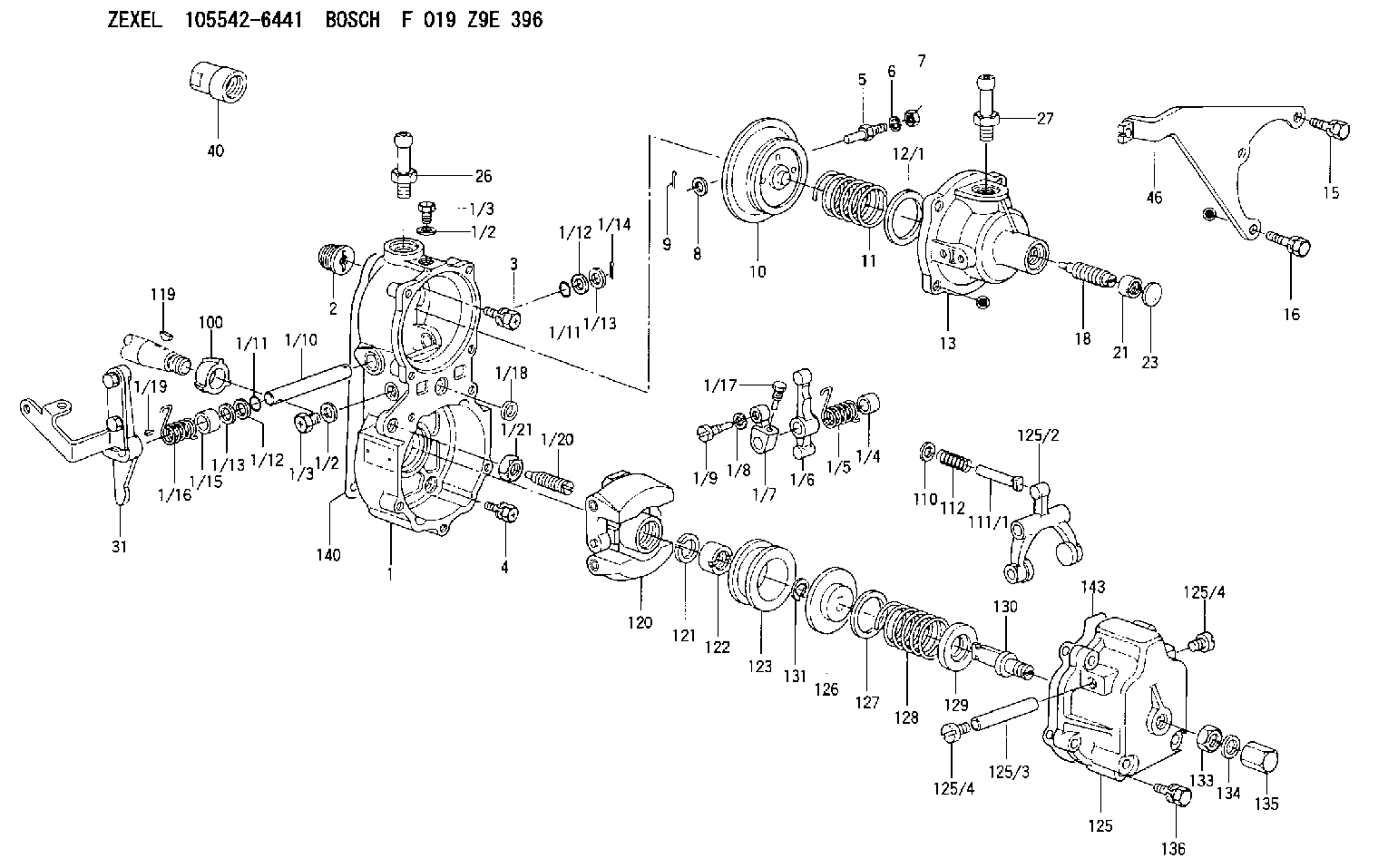
| 1. | [1] | 155014-7420 | GOVERNOR HOUSING |
| 1/2. | [2] | 026506-1040 | GASKET |
| 1/2. | [2] | 026506-1040 | GASKET |
| 1/3. | [2] | 029010-6010 | CAPSULE M6P1.0L7 |
| 1/3. | [2] | 029010-6010 | CAPSULE M6P1.0L7 |
| 1/4. | [1] | 155052-7600 | BUSHING |
| 1/5. | [1] | 155005-0800 | COILED SPRING |
| 1/6. | [1] | 155003-1000 | CONTROL LEVER |
| 1/7. | [1] | 155003-1100 | CONTROL LEVER |
| 1/8. | [1] | 029320-6010 | LOCKING WASHER |
| 1/9. | [1] | 155411-8100 | FLAT-HEAD SCREW |
| 1/10. | [1] | 155004-2800 | LEVER SHAFT |
| 1/11. | [2] | 029630-8060 | O-RING |
| 1/11. | [2] | 029630-8060 | O-RING |
| 1/12. | [2] | 029300-8010 | PLAIN WASHER |
| 1/12. | [2] | 029300-8010 | PLAIN WASHER |
| 1/13. | [0] | 029310-8010 | PLAIN WASHER D15&8.4T0.2 |
| 1/13. | [0] | 029310-8010 | PLAIN WASHER D15&8.4T0.2 |
| 1/13. | [0] | 029310-8020 | PLAIN WASHER D15&8.4T0.3 |
| 1/14. | [1] | 025520-1210 | SPLIT PIN |
| 1/15. | [1] | 155052-7600 | BUSHING |
| 1/16. | [1] | 155005-2500 | COILED SPRING |
| 1/17. | [1] | 155006-0300 | BLEEDER SCREW |
| 1/18. | [1] | 029620-5010 | PACKING RING |
| 1/19. | [1] | 025802-1010 | WOODRUFF KEY |
| 1/20. | [1] | 155007-0520 | HEADLESS SCREW |
| 1/21. | [1] | 029241-0060 | UNION NUT |
| 2. | [1] | 154007-0200 | ADAPTOR |
| 3. | [1] | 020018-1840 | BLEEDER SCREW |
| 4. | [4] | 029010-6810 | BLEEDER SCREW |
| 5. | [1] | 153406-0400 | BLEEDER SCREW |
| 6. | [1] | 014110-5440 | LOCKING WASHER |
| 7. | [1] | 013020-5220 | UNION NUT |
| 8. | [1] | 023500-6210 | PLAIN WASHER |
| 9. | [1] | 025520-1210 | SPLIT PIN |
| 10. | [1] | 155021-5621 | DIAPHRAGM |
| 11. | [1] | 155031-5700 | GOVERNOR SPRING |
| 12/1. | [0] | 155407-1100 | SHIM D37&30.5T0.5 |
| 12/1. | [0] | 155407-1200 | SHIM D37&30.5T1.0 |
| 12/1. | [0] | 155407-1300 | SHIM D37&30.5T1.5 |
| 12/1. | [0] | 155407-1400 | SHIM D37&30.5T2.0 |
| 12/1. | [0] | 155407-1500 | SHIM D37&30.5T2.5 |
| 12/1. | [0] | 155407-1600 | SHIM D37&30.5T3.0 |
| 12/1. | [0] | 155407-1700 | SHIM D37&30.5T0.2 |
| 12/1. | [0] | 155407-1800 | SHIM D37&30.5T0.3 |
| 13. | [1] | 155240-0500 | COVER |
| 15. | [3] | 020105-2040 | BLEEDER SCREW |
| 16. | [1] | 020105-2040 | BLEEDER SCREW |
| 18. | [1] | 155241-0920 | HEADLESS SCREW |
| 21. | [1] | 155245-0100 | HEXAGON NUT |
| 23. | [1] | 029142-0010 | CAPSULE |
| 26. | [1] | 029721-2050 | JOINT CONNECTION |
| 27. | [1] | 029721-2040 | JOINT CONNECTION |
| 31. | [1] | 155414-6420 | CONTROL LEVER |
| 40. | [1] | 155404-0200 | CAP |
| 46. | [1] | 155402-6520 | CLAMPING BAND |
| 100. | [1] | 155412-5200 | IMPELLER WHEEL |
| 110. | [1] | 029300-5010 | PLAIN WASHER |
| 111/1. | [0] | 155411-0200 | STOP PIN L51 |
| 111/1. | [0] | 155411-0300 | STOP PIN L51.5 |
| 111/1. | [0] | 155411-0400 | STOP PIN L52 |
| 111/1. | [0] | 155411-7800 | STOP PIN L48.5 |
| 111/1. | [0] | 155411-7900 | STOP PIN L49.5 |
| 111/1. | [0] | 155411-8000 | STOP PIN L50.5 |
| 111/1. | [0] | 155411-9700 | STOP PIN L48 |
| 111/1. | [0] | 155411-9800 | STOP PIN L49 |
| 111/1. | [0] | 155411-9900 | STOP PIN L50 |
| 112. | [1] | 155411-8200 | COILED SPRING |
| 119. | [1] | 025803-1610 | WOODRUFF KEY 16 MM |
| 120. | [1] | 154102-0720 | FLYWEIGHT ASSEMBLY |
| 121. | [1] | 029321-2020 | LOCKING WASHER |
| 122. | [1] | 029231-2030 | UNION NUT |
| 123. | [1] | 154123-0800 | SLIDING PIECE |
| 125. | [1] | 154405-4620 | COVER |
| 125/2. | [1] | 154406-2000 | FORK LINK |
| 125/3. | [1] | 154406-0500 | BEARING PIN |
| 125/4. | [2] | 029050-8050 | FLAT-HEAD SCREW |
| 125/4. | [2] | 029050-8050 | FLAT-HEAD SCREW |
| 126. | [1] | 154406-0200 | SLOTTED WASHER |
| 127. | [0] | 029302-5000 | SHIM D30&25T0.5 |
| 127B. | [0] | 029302-5010 | SHIM D30&25T1 |
| 128. | [1] | 155032-1700 | GOVERNOR SPRING |
| 128B. | [1] | 155032-1800 | GOVERNOR SPRING |
| 129. | [1] | 154406-0900 | SLOTTED WASHER |
| 130. | [1] | 154406-1100 | FLAT-HEAD SCREW |
| 131. | [1] | 016010-0740 | LOCKING WASHER |
| 133. | [1] | 023040-8040 | UNION NUT |
| 134. | [1] | 026508-1240 | GASKET D11.9&8.2T1.0 |
| 135. | [1] | 154035-1700 | CAP NUT |
| 136. | [5] | 029000-6810 | BLEEDER SCREW |
| 140. | [1] | 154390-0000 | GASKET |
| 143. | [1] | 154390-1000 | GASKET |
Include in #1:
101671-9320
as GOVERNOR
Cross reference number
Zexel num
Bosch num
Firm num
Name
Information:
1. Remove oil supply tube (1) and suction bell and tube (2). 2. Remove bolts (3) that hold the oil pump to the cylinder block and remove oil pump (4).3. To install, put oil pump (4) in position on the cylinder block. Install the bolts that hold the oil pump to the cylinder block.4. Put clean engine oil on the O-ring seals of the tubes.5. Install oil supply tube (1), suction bell and tube (2).End By:a. install oil panDisassemble Oil Pump
Start By:a. remove oil pump 1. Remove the bolt and washer that hold the gear on the shaft.2. Use Tool (A) and remove drive gear (1) from the shaft. Remove the key from the shaft. 3. Remove retainer (3) for the bypass valve. Remove the spring and the bypass valve.4. Remove cover (2) from the pump body. 5. Use Tool (B) and remove the bearings from the cover. 6. Remove gears (5) from pump body (4).7. Use Tool (B) and remove the bearings from pump body (4).Assemble Oil Pump
1. Use Tool (B) to install the bearings in the pump body. Install the bearings so the joint in the bearings is 30 15 degrees from the center line of the oil pump outlet passage (2). 2. Install idler gear and drive gear (5) in the oil pump body (4). Put clean engine oil on the bearings and the gears. 3. Use Tool (A) and install the bearings in cover (2). Install the bearings so the joint of the bearing bores toward oil pump outlet passage (6).4. Install bypass valve (7), spring (8) and the retainer.5. Install the key on the shaft. 6. Install gear (1) on the shaft. Install the washer and bolt that hold the gear on the shaft. Be sure the pump turns freely after assembly.End By:a. install oil pump