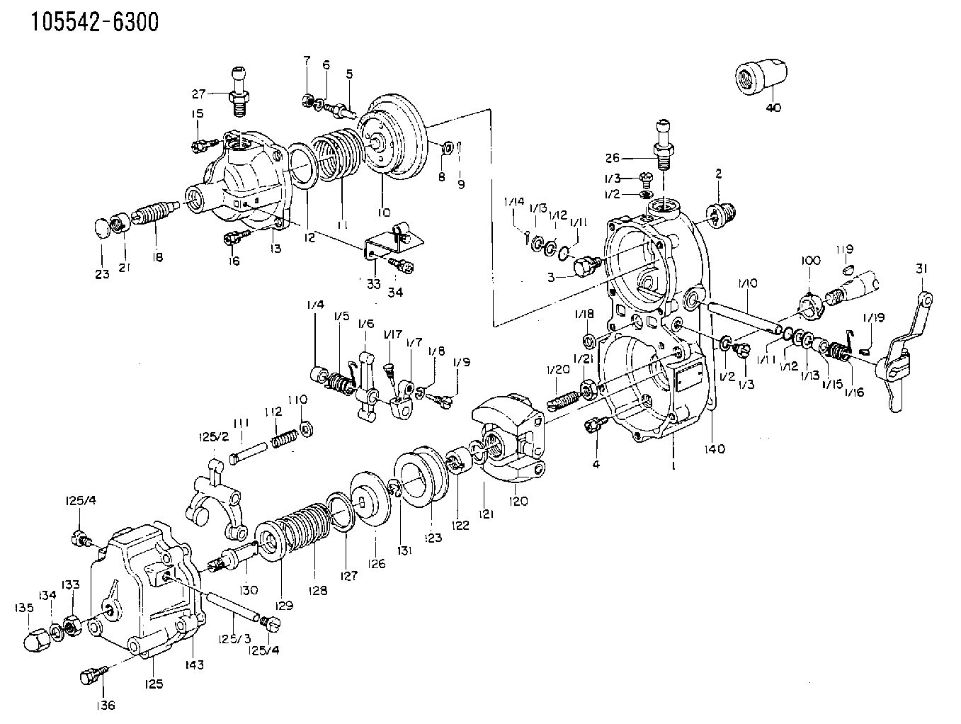
Information governor
BOSCH
F 019 Z1E 192
f019z1e192
ZEXEL
105542-6300
1055426300
ISUZU
9813101091
9813101091
Rating:
Scheme ###:
| 1. | [1] | 155014-7320 | GOVERNOR HOUSING |
| 1/1. | [1] | 155000-9110 | GOVERNOR HOUSING |
| 1/2. | [2] | 026506-1040 | GASKET D9.9&6.2T1 |
| 1/2. | [2] | 026506-1040 | GASKET D9.9&6.2T1 |
| 1/3. | [2] | 029010-6010 | CAPSULE M6P1.0L7 |
| 1/3. | [2] | 029010-6010 | CAPSULE M6P1.0L7 |
| 1/4. | [1] | 155052-7600 | BUSHING |
| 1/5. | [1] | 155005-0800 | COILED SPRING |
| 1/6. | [1] | 155003-1000 | CONTROL LEVER |
| 1/7. | [1] | 155003-1100 | CONTROL LEVER |
| 1/8. | [1] | 029320-6010 | LOCKING WASHER |
| 1/9. | [1] | 155411-8100 | FLAT-HEAD SCREW |
| 1/10. | [1] | 155004-2200 | LEVER SHAFT |
| 1/11. | [2] | 029630-8060 | O-RING |
| 1/11. | [2] | 029630-8060 | O-RING |
| 1/12. | [2] | 029300-8010 | PLAIN WASHER D15&8T1.00 |
| 1/12. | [2] | 029300-8010 | PLAIN WASHER D15&8T1.00 |
| 1/13. | [0] | 029310-8010 | PLAIN WASHER D15&8.4T0.2 |
| 1/13. | [0] | 029310-8010 | PLAIN WASHER D15&8.4T0.2 |
| 1/13. | [0] | 029310-8020 | PLAIN WASHER D15&8.4T0.3 |
| 1/14. | [1] | 025520-1210 | SPLIT PIN |
| 1/15. | [1] | 155052-7600 | BUSHING |
| 1/16. | [1] | 155005-0900 | COILED SPRING |
| 1/17. | [1] | 155006-0300 | BLEEDER SCREW |
| 1/18. | [1] | 029620-5010 | PACKING RING |
| 1/19. | [1] | 025802-1010 | WOODRUFF KEY |
| 1/20. | [1] | 155007-0520 | HEADLESS SCREW |
| 1/21. | [1] | 029241-0060 | UNION NUT |
| 2. | [1] | 154007-0200 | ADAPTOR |
| 3. | [1] | 020018-1840 | BLEEDER SCREW M8P1.25L18 |
| 4. | [4] | 029010-6810 | BLEEDER SCREW |
| 5. | [1] | 153406-0400 | BLEEDER SCREW |
| 6. | [1] | 014110-5440 | LOCKING WASHER |
| 7. | [1] | 013020-5220 | UNION NUT M5P0.8H4 |
| 8. | [1] | 023500-6210 | PLAIN WASHER D11&6.4T1.5 |
| 9. | [1] | 025520-1210 | SPLIT PIN |
| 10. | [1] | 155020-8720 | DIAPHRAGM |
| 11. | [1] | 155031-9500 | GOVERNOR SPRING |
| 12/1. | [0] | 155407-1100 | SHIM D37&30.5T0.5 |
| 12/1. | [0] | 155407-1200 | SHIM D37&30.5T1.0 |
| 12/1. | [0] | 155407-1300 | SHIM D37&30.5T1.5 |
| 12/1. | [0] | 155407-1400 | SHIM D37&30.5T2.0 |
| 12/1. | [0] | 155407-1500 | SHIM D37&30.5T2.5 |
| 12/1. | [0] | 155407-1600 | SHIM D37&30.5T3.0 |
| 12/1. | [0] | 155407-1700 | SHIM D37&30.5T0.2 |
| 12/1. | [0] | 155407-1800 | SHIM D37&30.5T0.3 |
| 13. | [1] | 155240-0500 | COVER |
| 15. | [3] | 020105-1640 | BLEEDER SCREW M5P0.8L16 |
| 16. | [1] | 029010-5350 | BLEEDER SCREW |
| 18. | [1] | 155241-3320 | HEADLESS SCREW |
| 21. | [1] | 155245-0100 | HEXAGON NUT |
| 23. | [1] | 029142-0010 | CAPSULE |
| 26. | [1] | 029721-2050 | JOINT CONNECTION |
| 27. | [1] | 029721-2040 | JOINT CONNECTION |
| 31. | [1] | 155400-6920 | CONTROL LEVER |
| 34. | [2] | 029050-5040 | FLAT-HEAD SCREW M5P0.8L9 |
| 35. | [1] | 155402-4620 | CLAMPING BAND |
| 40. | [1] | 155404-0200 | CAP |
| 100. | [1] | 155412-5200 | IMPELLER WHEEL |
| 110. | [1] | 029300-5010 | PLAIN WASHER |
| 111/1. | [0] | 155411-0200 | STOP PIN L51 |
| 111/1. | [0] | 155411-0300 | STOP PIN L51.5 |
| 111/1. | [0] | 155411-0400 | STOP PIN L52 |
| 111/1. | [0] | 155411-7800 | STOP PIN L48.5 |
| 111/1. | [0] | 155411-7900 | STOP PIN L49.5 |
| 111/1. | [0] | 155411-8000 | STOP PIN L50.5 |
| 111/1. | [0] | 155411-9700 | STOP PIN L48 |
| 111/1. | [0] | 155411-9800 | STOP PIN L49 |
| 111/1. | [0] | 155411-9900 | STOP PIN L50 |
| 112. | [1] | 155411-8200 | COILED SPRING |
| 119. | [1] | 025803-1610 | WOODRUFF KEY |
| 120. | [1] | 154102-0720 | FLYWEIGHT ASSEMBLY |
| 121. | [1] | 029321-2020 | LOCKING WASHER |
| 122. | [1] | 029231-2030 | UNION NUT |
| 123. | [1] | 154123-0800 | SLIDING PIECE |
| 125. | [1] | 154405-4620 | COVER |
| 125/2. | [1] | 154406-2000 | FORK LINK |
| 125/3. | [1] | 154406-0500 | BEARING PIN |
| 125/4. | [2] | 029050-8050 | FLAT-HEAD SCREW |
| 125/4. | [2] | 029050-8050 | FLAT-HEAD SCREW |
| 126. | [1] | 154406-0200 | SLOTTED WASHER |
| 127. | [0] | 029302-5000 | SHIM D30&25T0.5 |
| 127B. | [0] | 029302-5010 | SHIM D30&25T1 |
| 128. | [1] | 155032-0800 | GOVERNOR SPRING |
| 128B. | [1] | 155032-2600 | GOVERNOR SPRING |
| 129. | [1] | 154406-0900 | SLOTTED WASHER |
| 130. | [1] | 154406-1100 | FLAT-HEAD SCREW |
| 131. | [1] | 016010-0740 | LOCKING WASHER |
| 133. | [1] | 023040-8040 | UNION NUT |
| 134. | [1] | 026508-1240 | GASKET D11.9&8.2T1 |
| 135. | [1] | 154035-0600 | CAP NUT |
| 136. | [5] | 029000-6810 | BLEEDER SCREW |
| 140. | [1] | 154390-0000 | GASKET |
| 143. | [1] | 154390-1000 | GASKET |
Cross reference number
Zexel num
Bosch num
Firm num
Name
105542-6300
9813101091 ISUZU
GOVERNOR
* K 14JP COMBINED GOVERNOR GOV RBD GOV
* K 14JP COMBINED GOVERNOR GOV RBD GOV
Information:
Assemble Governor
*Pump and Governor Reconditioning Tool Group1. Put the fuel injection pump housing in position on Tool (A). Install race (3), bearing (2) and race (1) on the end of the camshaft in the fuel injection pump housing. 2. Put flyweights (5) in position on carrier assembly (4), and install dowels (6) to hold the flyweights in place. The flyweights must move freely on the dowels and have 0.010 to 0.230 mm (.0004 to .0090 in) end play. 3. Install governor shaft (7) on carrier assembly (4). 4. Install dowel (8) in governor shaft (7), and slide carrier assembly (4) down on the governor shaft until dowel (8) fits into the slot in the carrier assembly.5. Install carrier assembly (4) on the end of the camshaft. 6. Install race (12), bearing (11), race (10) and ring (9) on riser (13). 7. Install riser (13) and spring (14), if equipped, on the governor shaft. 8. Install spool (18) and ring (19) on seat (17), and use Tool (B) to install ring (20) to hold them in position.9. Install seat (17) on spring (16) and spring (16) on shield (15). 10. Install dashpot assembly (21) on the governor shaft. 11. Install ring (22) in the groove on the governor shaft. Install sleeve (23), spring (25), the sleeve and bearing (24) on the governor shaft. 12. Use Tool (C) to hold spring (25) under compression, and install the ring in the groove on the governor shaft. 13. Install O-ring seal (26) on sleeve (27). Install piston (29) and sleeve (27) in the governor servo as shown.14. Install valve (28) in the governor servo as shown. 15. Install lockring (33) in the groove near the center of valve (28). Put sleeve (34), spring broken link spring (35) and seat (36) in position on valve (28), and install lockring (37) to hold them in place. 16. Put governor servo (30) in position on the fuel injection pump housing with piston (29) engaged over the rack. Make sure the lever is engaged in the slot groove of riser (13). 17. If dowel (43) was removed, install it in block (44) 31 0.5 mm (1.22 .02 in) above the outside surface of the block.18. Install bolt (45) in block (44) and spring (38) on bolt (45).19. Install stop screw (40) and the locknut on collar (42). Install power setting screw (41) and the locknut on the collar.20. Install collar (42) on bolt (45). Make an alignment of the hole in the collar with the notch in bolt (45), and install bolt (39). 21. If the dowels that align block (44) with the front governor housing were removed, install them 4.0 0.5 mm (.16 .02 in) above the outside surface of the front governor housing.22. Put block (44) in position on the front governor housing with the holes in the block in alignment with dowels in the front governor housing. 23. Install dowels (46) in the front governor housing 6.0 0.5
*Pump and Governor Reconditioning Tool Group1. Put the fuel injection pump housing in position on Tool (A). Install race (3), bearing (2) and race (1) on the end of the camshaft in the fuel injection pump housing. 2. Put flyweights (5) in position on carrier assembly (4), and install dowels (6) to hold the flyweights in place. The flyweights must move freely on the dowels and have 0.010 to 0.230 mm (.0004 to .0090 in) end play. 3. Install governor shaft (7) on carrier assembly (4). 4. Install dowel (8) in governor shaft (7), and slide carrier assembly (4) down on the governor shaft until dowel (8) fits into the slot in the carrier assembly.5. Install carrier assembly (4) on the end of the camshaft. 6. Install race (12), bearing (11), race (10) and ring (9) on riser (13). 7. Install riser (13) and spring (14), if equipped, on the governor shaft. 8. Install spool (18) and ring (19) on seat (17), and use Tool (B) to install ring (20) to hold them in position.9. Install seat (17) on spring (16) and spring (16) on shield (15). 10. Install dashpot assembly (21) on the governor shaft. 11. Install ring (22) in the groove on the governor shaft. Install sleeve (23), spring (25), the sleeve and bearing (24) on the governor shaft. 12. Use Tool (C) to hold spring (25) under compression, and install the ring in the groove on the governor shaft. 13. Install O-ring seal (26) on sleeve (27). Install piston (29) and sleeve (27) in the governor servo as shown.14. Install valve (28) in the governor servo as shown. 15. Install lockring (33) in the groove near the center of valve (28). Put sleeve (34), spring broken link spring (35) and seat (36) in position on valve (28), and install lockring (37) to hold them in place. 16. Put governor servo (30) in position on the fuel injection pump housing with piston (29) engaged over the rack. Make sure the lever is engaged in the slot groove of riser (13). 17. If dowel (43) was removed, install it in block (44) 31 0.5 mm (1.22 .02 in) above the outside surface of the block.18. Install bolt (45) in block (44) and spring (38) on bolt (45).19. Install stop screw (40) and the locknut on collar (42). Install power setting screw (41) and the locknut on the collar.20. Install collar (42) on bolt (45). Make an alignment of the hole in the collar with the notch in bolt (45), and install bolt (39). 21. If the dowels that align block (44) with the front governor housing were removed, install them 4.0 0.5 mm (.16 .02 in) above the outside surface of the front governor housing.22. Put block (44) in position on the front governor housing with the holes in the block in alignment with dowels in the front governor housing. 23. Install dowels (46) in the front governor housing 6.0 0.5