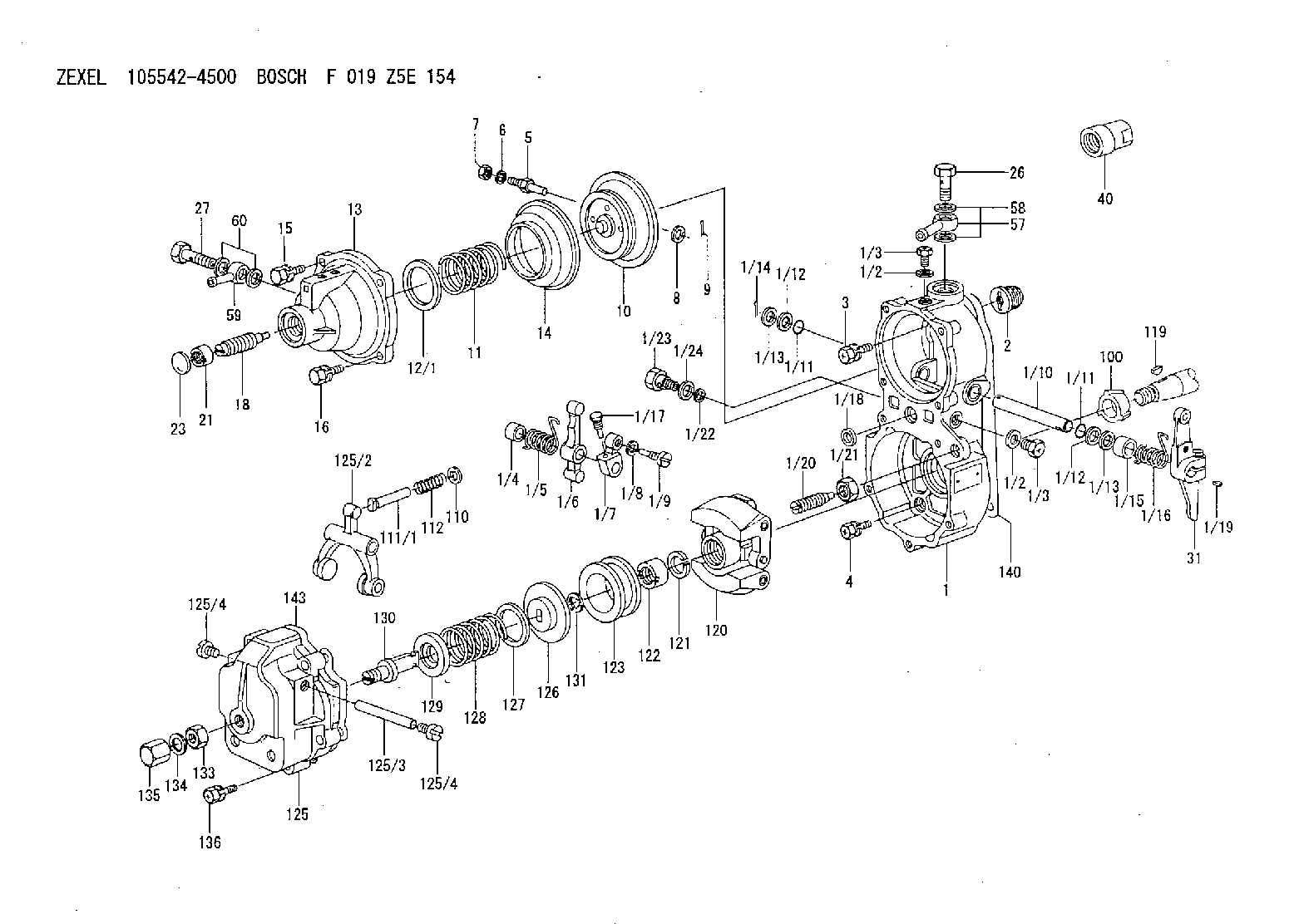
Information governor
BOSCH
F 019 Z5E 154
f019z5e154
ZEXEL
105542-4500
1055424500
NISSAN-DIESEL
1920090065
1920090065
Rating:
Scheme ###:
| 1. | [1] | 155015-0120 | GOVERNOR HOUSING |
| 1/2. | [2] | 026506-1040 | GASKET D9.9&6.2T1 |
| 1/2. | [2] | 026506-1040 | GASKET D9.9&6.2T1 |
| 1/3. | [2] | 029010-6010 | CAPSULE M6P1.0L7 |
| 1/3. | [2] | 029010-6010 | CAPSULE M6P1.0L7 |
| 1/4. | [1] | 155052-7600 | BUSHING |
| 1/5. | [1] | 155005-0800 | COILED SPRING |
| 1/6. | [1] | 155003-2200 | CONTROL LEVER |
| 1/7. | [1] | 155003-1100 | CONTROL LEVER |
| 1/8. | [1] | 029320-6010 | LOCKING WASHER |
| 1/9. | [1] | 155411-8100 | FLAT-HEAD SCREW |
| 1/10. | [1] | 155004-3700 | LEVER SHAFT |
| 1/11. | [2] | 029630-8060 | O-RING |
| 1/11. | [2] | 029630-8060 | O-RING |
| 1/12. | [2] | 029300-8010 | PLAIN WASHER D15&8T1.00 |
| 1/12. | [2] | 029300-8010 | PLAIN WASHER D15&8T1.00 |
| 1/13. | [0] | 029310-8010 | PLAIN WASHER D15&8.4T0.2 |
| 1/13. | [0] | 029310-8020 | PLAIN WASHER D15&8.4T0.3 |
| 1/13. | [0] | 029310-8020 | PLAIN WASHER D15&8.4T0.3 |
| 1/14. | [1] | 025520-1210 | SPLIT PIN |
| 1/15. | [1] | 155052-7600 | BUSHING |
| 1/16. | [1] | 155005-0900 | COILED SPRING |
| 1/17. | [1] | 155006-0300 | BLEEDER SCREW |
| 1/18. | [1] | 029620-5010 | PACKING RING |
| 1/19. | [1] | 025802-1010 | WOODRUFF KEY |
| 1/20. | [1] | 155007-0520 | HEADLESS SCREW |
| 1/21. | [1] | 029241-0060 | UNION NUT |
| 1/22. | [1] | 026506-1040 | GASKET D9.9&6.2T1 |
| 1/23. | [1] | 155418-3820 | DRAINAGE PIPE |
| 1/24. | [1] | 139509-0000 | GASKET D13.9&9.2T1 |
| 2. | [1] | 154007-0200 | ADAPTOR |
| 3. | [1] | 020018-1840 | BLEEDER SCREW M8P1.25L18 |
| 4. | [4] | 029010-6810 | BLEEDER SCREW |
| 5. | [1] | 153406-0400 | BLEEDER SCREW |
| 6. | [1] | 014110-5440 | LOCKING WASHER |
| 7. | [1] | 013020-5220 | UNION NUT M5P0.8H4 |
| 8. | [1] | 023500-6210 | PLAIN WASHER D11&6.4T1.5 |
| 9. | [1] | 025520-1210 | SPLIT PIN |
| 10. | [1] | 155029-4620 | DIAPHRAGM |
| 11. | [1] | 155031-9500 | GOVERNOR SPRING |
| 12/1. | [0] | 155407-1100 | SHIM D37&30.5T0.5 |
| 12/1. | [0] | 155407-1200 | SHIM D37&30.5T1.0 |
| 12/1. | [0] | 155407-1300 | SHIM D37&30.5T1.5 |
| 12/1. | [0] | 155407-1400 | SHIM D37&30.5T2.0 |
| 12/1. | [0] | 155407-1500 | SHIM D37&30.5T2.5 |
| 12/1. | [0] | 155407-1600 | SHIM D37&30.5T3.0 |
| 12/1. | [0] | 155407-1700 | SHIM D37&30.5T0.2 |
| 12/1. | [0] | 155407-1800 | SHIM D37&30.5T0.3 |
| 13. | [1] | 155240-0500 | COVER |
| 14. | [1] | 155019-0220 | FILLER PIECE |
| 15. | [3] | 020105-1640 | BLEEDER SCREW M5P0.8L16 |
| 16. | [1] | 020105-1640 | BLEEDER SCREW M5P0.8L16 |
| 18. | [1] | 155241-3920 | HEADLESS SCREW |
| 21. | [1] | 155245-0100 | HEXAGON NUT |
| 23. | [1] | 029142-0010 | CAPSULE |
| 26. | [1] | 029731-2010 | EYE BOLT |
| 27. | [1] | 029731-2010 | EYE BOLT |
| 31. | [1] | 155400-9920 | CONTROL LEVER |
| 40. | [1] | 154050-1720 | STOPPING DEVICE |
| 57. | [1] | 029711-2330 | INLET UNION |
| 58. | [2] | 029341-2010 | GASKET |
| 59. | [1] | 029711-2130 | INLET UNION |
| 60. | [2] | 029341-2010 | GASKET |
| 100. | [1] | 155412-5200 | IMPELLER WHEEL |
| 110. | [1] | 029300-5010 | PLAIN WASHER |
| 111/1. | [0] | 155411-0200 | STOP PIN L51 |
| 111/1. | [0] | 155411-0300 | STOP PIN L51.5 |
| 111/1. | [0] | 155411-0400 | STOP PIN L52 |
| 111/1. | [0] | 155411-7800 | STOP PIN L48.5 |
| 111/1. | [0] | 155411-7900 | STOP PIN L49.5 |
| 111/1. | [0] | 155411-8000 | STOP PIN L50.5 |
| 111/1. | [0] | 155411-9700 | STOP PIN L48 |
| 111/1. | [0] | 155411-9800 | STOP PIN L49 |
| 111/1. | [0] | 155411-9900 | STOP PIN L50 |
| 112. | [1] | 155411-8200 | COILED SPRING |
| 119. | [1] | 025803-1610 | WOODRUFF KEY |
| 120. | [1] | 154102-0620 | FLYWEIGHT ASSEMBLY |
| 121. | [1] | 029321-2020 | LOCKING WASHER |
| 122. | [1] | 029231-2030 | UNION NUT |
| 123. | [1] | 154123-0800 | SLIDING PIECE |
| 125. | [1] | 154405-6220 | COVER |
| 125/2. | [1] | 154405-6300 | FORK LINK |
| 125/3. | [1] | 154406-0500 | BEARING PIN |
| 125/4. | [2] | 029050-8050 | FLAT-HEAD SCREW |
| 125/4. | [2] | 029050-8050 | FLAT-HEAD SCREW |
| 126. | [1] | 154405-6400 | SLOTTED WASHER |
| 127. | [0] | 029302-5000 | SHIM D30&25T0.5 |
| 127B. | [0] | 029302-5010 | SHIM D30&25T1 |
| 128. | [1] | 155032-6900 | COILED SPRING |
| 128B. | [1] | 155031-9800 | GOVERNOR SPRING |
| 129. | [1] | 154406-0900 | SLOTTED WASHER |
| 130. | [1] | 154406-1100 | FLAT-HEAD SCREW |
| 131. | [1] | 016010-0740 | LOCKING WASHER |
| 133. | [1] | 023040-8040 | UNION NUT |
| 134. | [1] | 026508-1240 | GASKET D11.9&8.2T1 |
| 135. | [1] | 154035-1700 | CAP NUT |
| 136. | [5] | 029000-6810 | BLEEDER SCREW |
| 140. | [1] | 154390-0000 | GASKET |
| 143. | [1] | 154390-1000 | GASKET |
Include in #1:
101441-9590
as GOVERNOR
Cross reference number
Zexel num
Bosch num
Firm num
Name
Information:
Start By:a. disassemble governorb. remove fuel injection pumps 1. Remove cover (1) from the fuel injection pump housing. 2. Remove rack (2) from the fuel injection pump housing.
If the original lifters are to be installed in the fuel injection pump housing, put identification marks on them as to their location in the housing.
3. Remove lifters (3) from the fuel injection pump housing. 4. Put the fuel injection pump housing on end on blocks, and use Tool (A) to remove snap ring (4) from the camshaft. 5. Use a soft hammer to push the camshaft toward the governor end of the fuel injection pump housing to loosen washer (5) on the camshaft. Remove washer (5). 6. Remove camshaft (6) from the fuel injection pump housing. 7. Remove bearings (7) from the drive end of the fuel injection pump housing. 8. Remove bearings (8) from the governor end of the fuel injection pump housing.Assemble Fuel Injection Pump Housing
Be sure all oil passages are clear and put clean engine oil on all parts before assembly.1. Use Tool (A) to install bearing (2) in the governor end of the fuel injection pump housing with joint (3) toward the top of the fuel injection pump housing. Install the bearing so it is 0.25 0.20 mm (.010 0.008 in) below the surface of the housing.2. Use Tool (A) to install bearing (1) in the governor end of the fuel injection pump housing so it is 7.16 0.13 mm (0.282 0.005 in) below the surface of the housing. 3. Use Tool (A) to install bearing (4) in the drive end of the fuel injection pump housing with the joint in the bearing toward the top of the fuel injection pump housing. Install the bearing so it is 1.00 0.25 mm (0.039 0.010 in) below the surface of the housing. 4. Install plate assembly (6) of Tool (C) on the drive end of the fuel injection pump housing to install the bearing for the rack. Use clean grease to hold the new rack bearing on driver (5) of Tool (C). Install the driver and bearing in plate assembly (6) with the groove in the driver in alignment with the pin in the plate. Use a hammer to push the bearing into position. The bearing will be installed to the correct depth when the shoulder of the driver is against plate assembly (6).5. Remove Tool (C) from the fuel injection pump housing. The rack bearing must be installed so it is 0.25 0.25 mm (0.010 0.010 in) below the surface of the housing. 6. Install camshaft (7) in the fuel injection pump housing.7. Put the fuel injection pump housing on end, and put a block under the camshaft. 8. Put washer (9) over the end of the camshaft, and use Tool (A) and a spacer (8) that has an inside diameter of 38.1 mm (1.5 in) and a length of 31.75 mm (1.25 in) to push the washer