Information governor
BOSCH
9 420 610 001
9420610001
ZEXEL
105542-3610
1055423610
NISSAN
19200C6807
19200c6807

Rating:
Scheme ###:
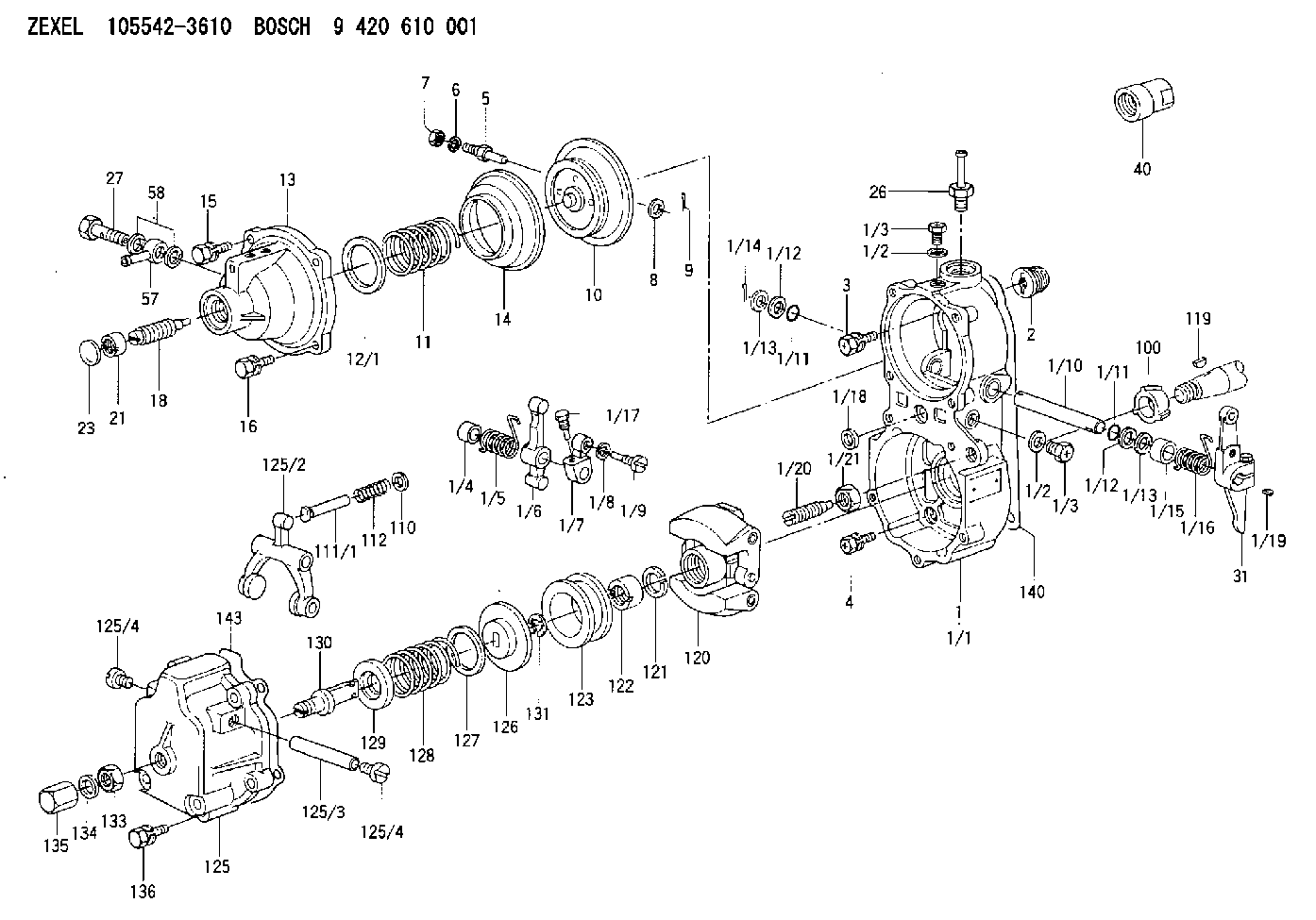
| 1. | [1] | 155014-8720 | GOVERNOR HOUSING |
| 1/1. | [1] | 155014-8710 | GOVERNOR HOUSING |
| 1/2. | [2] | 026506-1040 | GASKET D9.9&6.2T1 |
| 1/2. | [2] | 026506-1040 | GASKET D9.9&6.2T1 |
| 1/3. | [2] | 029010-6010 | CAPSULE M6P1.0L7 |
| 1/3. | [2] | 029010-6010 | CAPSULE M6P1.0L7 |
| 1/4. | [1] | 155052-7600 | BUSHING |
| 1/5. | [1] | 155005-0800 | COILED SPRING |
| 1/6. | [1] | 155003-1000 | CONTROL LEVER |
| 1/7. | [1] | 155003-1100 | CONTROL LEVER |
| 1/8. | [1] | 029320-6010 | LOCKING WASHER |
| 1/9. | [1] | 155411-8100 | FLAT-HEAD SCREW |
| 1/10. | [1] | 155004-3400 | LEVER SHAFT |
| 1/11. | [2] | 029630-8060 | O-RING |
| 1/11. | [2] | 029630-8060 | O-RING |
| 1/12. | [2] | 139308-0600 | PLAIN WASHER |
| 1/12. | [2] | 139308-0600 | PLAIN WASHER |
| 1/13. | [0] | 029310-8010 | PLAIN WASHER D15&8.4T0.2 |
| 1/13. | [0] | 029310-8020 | PLAIN WASHER D15&8.4T0.3 |
| 1/13. | [0] | 029310-8020 | PLAIN WASHER D15&8.4T0.3 |
| 1/14. | [1] | 025520-1210 | SPLIT PIN |
| 1/15. | [1] | 155052-7600 | BUSHING |
| 1/16. | [1] | 155005-0900 | COILED SPRING |
| 1/17. | [1] | 155006-0300 | BLEEDER SCREW |
| 1/18. | [1] | 029620-5010 | PACKING RING |
| 1/19. | [1] | 025802-1010 | WOODRUFF KEY |
| 1/20. | [1] | 155007-0520 | HEADLESS SCREW |
| 1/21. | [1] | 139210-0000 | UNION NUT |
| 2. | [1] | 154007-0200 | ADAPTOR |
| 3. | [1] | 020018-1840 | BLEEDER SCREW M8P1.25L18 |
| 4. | [4] | 029010-6810 | BLEEDER SCREW |
| 5. | [1] | 153406-0400 | BLEEDER SCREW |
| 6. | [1] | 014110-5440 | LOCKING WASHER |
| 7. | [1] | 013020-5220 | UNION NUT M5P0.8H4 |
| 8. | [1] | 023500-6210 | PLAIN WASHER D11&6.4T1.5 |
| 9. | [1] | 025520-1210 | SPLIT PIN |
| 10. | [1] | 155020-3620 | DIAPHRAGM |
| 11. | [1] | 155032-6700 | COILED SPRING |
| 12/1. | [0] | 155407-1100 | SHIM D37&30.5T0.5 |
| 12/1. | [0] | 155407-1200 | SHIM D37&30.5T1.0 |
| 12/1. | [0] | 155407-1300 | SHIM D37&30.5T1.5 |
| 12/1. | [0] | 155407-1400 | SHIM D37&30.5T2.0 |
| 12/1. | [0] | 155407-1500 | SHIM D37&30.5T2.5 |
| 12/1. | [0] | 155407-1600 | SHIM D37&30.5T3.0 |
| 12/1. | [0] | 155407-1700 | SHIM D37&30.5T0.2 |
| 12/1. | [0] | 155407-1800 | SHIM D37&30.5T0.3 |
| 13. | [1] | 155240-1320 | COVER |
| 14. | [1] | 155019-0220 | FILLER PIECE |
| 15. | [3] | 020105-1640 | BLEEDER SCREW M5P0.8L16 |
| 16. | [1] | 020105-1640 | BLEEDER SCREW M5P0.8L16 |
| 18. | [1] | 155241-0920 | HEADLESS SCREW |
| 21. | [1] | 155245-0100 | HEXAGON NUT |
| 23. | [1] | 029142-0010 | CAPSULE |
| 26. | [1] | 029721-2050 | JOINT CONNECTION |
| 27. | [1] | 029731-2010 | EYE BOLT |
| 31. | [1] | 155400-9920 | CONTROL LEVER |
| 40. | [1] | 154050-1720 | STOPPING DEVICE |
| 57. | [1] | 029711-2330 | INLET UNION |
| 58. | [2] | 029341-2010 | GASKET |
| 100. | [1] | 155412-5200 | IMPELLER WHEEL |
| 110. | [1] | 029300-5010 | PLAIN WASHER |
| 111/1. | [0] | 155411-0200 | STOP PIN L51 |
| 111/1. | [0] | 155411-0300 | STOP PIN L51.5 |
| 111/1. | [0] | 155411-0400 | STOP PIN L52 |
| 111/1. | [0] | 155411-7800 | STOP PIN L48.5 |
| 111/1. | [0] | 155411-7900 | STOP PIN L49.5 |
| 111/1. | [0] | 155411-8000 | STOP PIN L50.5 |
| 111/1. | [0] | 155411-9700 | STOP PIN L48 |
| 111/1. | [0] | 155411-9800 | STOP PIN L49 |
| 111/1. | [0] | 155411-9900 | STOP PIN L50 |
| 112. | [1] | 155411-8200 | COILED SPRING |
| 119. | [1] | 025803-1610 | WOODRUFF KEY |
| 120. | [1] | 154102-0620 | FLYWEIGHT ASSEMBLY |
| 121. | [1] | 029321-2020 | LOCKING WASHER |
| 122. | [1] | 029231-2030 | UNION NUT |
| 123. | [1] | 154123-0800 | SLIDING PIECE |
| 125. | [1] | 154405-4620 | COVER |
| 125/2. | [1] | 154406-2000 | FORK LINK |
| 125/3. | [1] | 154406-0500 | BEARING PIN |
| 125/4. | [2] | 029050-8050 | FLAT-HEAD SCREW |
| 125/4. | [2] | 029050-8050 | FLAT-HEAD SCREW |
| 126. | [1] | 154406-0200 | SLOTTED WASHER |
| 127. | [0] | 029302-5000 | SHIM D30&25T0.5 |
| 127B. | [0] | 029302-5010 | SHIM D30&25T1 |
| 128. | [1] | 155032-6000 | GOVERNOR SPRING |
| 128B. | [1] | 155032-4300 | GOVERNOR SPRING |
| 129. | [1] | 154406-0900 | SLOTTED WASHER |
| 130. | [1] | 154406-1100 | FLAT-HEAD SCREW |
| 131. | [1] | 016010-0740 | LOCKING WASHER |
| 133. | [1] | 023040-8040 | UNION NUT |
| 134. | [1] | 026508-1240 | GASKET D11.9&8.2T1 |
| 135. | [1] | 154035-1700 | CAP NUT |
| 136. | [5] | 029000-6810 | BLEEDER SCREW |
| 140. | [1] | 154390-0000 | GASKET |
| 143. | [1] | 154390-1000 | GASKET |
Include in #1:
101631-9661
as GOVERNOR
Cross reference number
Zexel num
Bosch num
Firm num
Name
19200C6807 NISSAN
GOVERNOR
* K 14JP COMBINED GOVERNOR GOV RBD GOV
* K 14JP COMBINED GOVERNOR GOV RBD GOV
19200C6807 NISSAN-DIESEL
GOVERNOR
* K 14JP COMBINED GOVERNOR GOV RBD GOV
* K 14JP COMBINED GOVERNOR GOV RBD GOV
Information:
ACTION REQUIRED
Take the following actions before or after a failure occurs on one or more injectors in any of the engines listed in this service letter.
- If one or more injectors fail it may be necessary to replace up to 6 injectors at the time of repair.
There will be situations when all 6 injectors do not have to be replaced. Refer to next paragraph to determine which injectors should be replaced.
- If an injector repair has previously been performed after approximately 01Oct07 on any of the listed engines, only the injectors that were not replaced at that time should be replaced. This should further be verified by comparing the injector serial numbers in the engine to a range of 3B115776403B to 3B11676551F9. Disregard the first and last two characters in the serial number (in this case "3B" and "3B" in the first serial number and "3B" and "F9" in the second serial number). The reason for verifying the serial number range is due to a batch change of the internal part that is failing. The change was made after serial number 3B11676551F9.
Only injectors falling within the range of 11577640-11676551 should be replaced.
- If the suspect injector can not be identified by using the automatic cylinder cutout test use the two methods below.
- First, run a manual cylinder cutout test at a high engine speed with some load on the engine. When the injector that has failed is cutout, the sound of the engine should be more normal as opposed to the loud knocking heard when the failed injector is active. The second method is to unplug the wiring harness at the valve cover base that sends current to the injector solenoids as well as the harness connection for the injection actuation pressure sensor. By making these disconnections, the fuel injectors will not fire and the HEUI pump will go to maximum actuation pressure. Then remove the valve cover and crank the engine. The injectors that have failed should expel more oil (from the HEUI System) than those that are not failed.
-Refer to RENR9579 for removal/install procedure of the unit injector.
-The serial number of all injectors replaced in an engine covered under this service letter must be documented in the claims story.
SERVICE CLAIM ALLOWANCES
Product smu/age