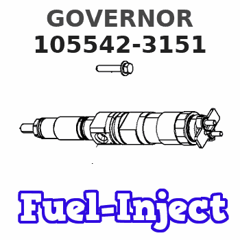
Information governor
BOSCH
F 019 Z1E 653
f019z1e653
ZEXEL
105542-3151
1055423151
NISSAN
19200J5502
19200j5502
Rating:
Scheme ###:
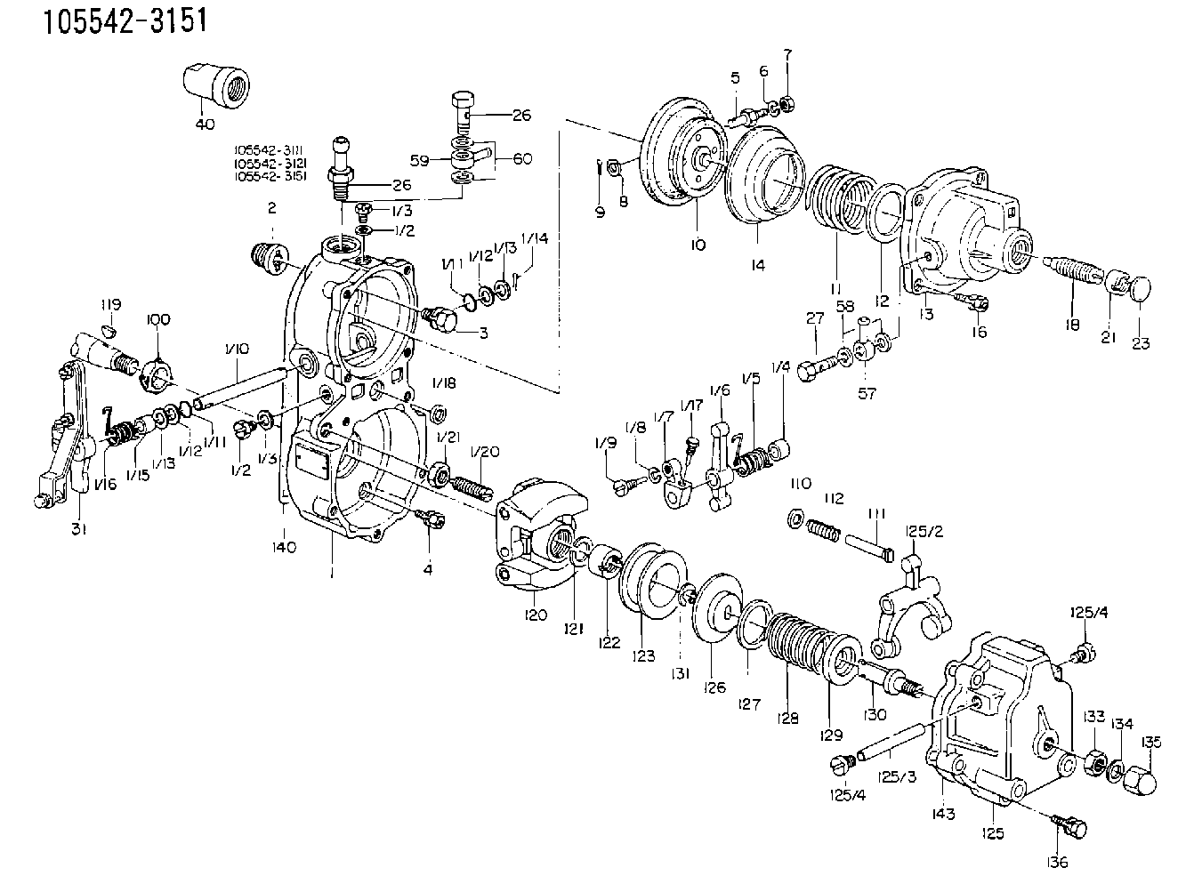
| 1. | [1] | 155014-7820 | GOVERNOR HOUSING |
| 1/2. | [2] | 026506-1040 | GASKET D9.9&6.2T1 |
| 1/2. | [2] | 026506-1040 | GASKET D9.9&6.2T1 |
| 1/3. | [2] | 029010-6010 | CAPSULE M6P1.0L7 |
| 1/3. | [2] | 029010-6010 | CAPSULE M6P1.0L7 |
| 1/4. | [1] | 155052-7600 | BUSHING |
| 1/5. | [1] | 155005-0800 | COILED SPRING |
| 1/6. | [1] | 155003-1000 | CONTROL LEVER |
| 1/7. | [1] | 155003-1100 | CONTROL LEVER |
| 1/8. | [1] | 029320-6010 | LOCKING WASHER |
| 1/9. | [1] | 155411-8100 | FLAT-HEAD SCREW |
| 1/10. | [1] | 155004-2800 | LEVER SHAFT |
| 1/11. | [2] | 029630-8060 | O-RING |
| 1/11. | [2] | 029630-8060 | O-RING |
| 1/12. | [2] | 029300-8010 | PLAIN WASHER D15&8T1.00 |
| 1/12. | [2] | 029300-8010 | PLAIN WASHER D15&8T1.00 |
| 1/13. | [0] | 029310-8010 | PLAIN WASHER D15&8.4T0.2 |
| 1/13. | [0] | 029310-8010 | PLAIN WASHER D15&8.4T0.2 |
| 1/13. | [0] | 029310-8020 | PLAIN WASHER D15&8.4T0.3 |
| 1/14. | [1] | 025520-1210 | SPLIT PIN |
| 1/15. | [1] | 155052-7600 | BUSHING |
| 1/16. | [1] | 155005-3000 | COILED SPRING |
| 1/17. | [1] | 155006-0300 | BLEEDER SCREW |
| 1/18. | [1] | 029620-5010 | PACKING RING |
| 1/19. | [1] | 025802-1010 | WOODRUFF KEY |
| 1/20. | [1] | 155007-1420 | HEADLESS SCREW |
| 1/21. | [1] | 029241-0060 | UNION NUT |
| 2. | [1] | 154007-0200 | ADAPTOR |
| 3. | [1] | 020018-1840 | BLEEDER SCREW M8P1.25L18 |
| 4. | [4] | 029010-6810 | BLEEDER SCREW |
| 5. | [1] | 153406-0400 | BLEEDER SCREW |
| 6. | [1] | 014110-5440 | LOCKING WASHER |
| 7. | [1] | 013020-5220 | UNION NUT M5P0.8H4 |
| 8. | [1] | 023500-6210 | PLAIN WASHER D11&6.4T1.5 |
| 9. | [1] | 025520-1210 | SPLIT PIN |
| 10. | [1] | 155021-5621 | DIAPHRAGM |
| 11. | [1] | 155032-2100 | GOVERNOR SPRING |
| 12/1. | [0] | 155407-1100 | SHIM D37&30.5T0.5 |
| 12/1. | [0] | 155407-1200 | SHIM D37&30.5T1.0 |
| 12/1. | [0] | 155407-1300 | SHIM D37&30.5T1.5 |
| 12/1. | [0] | 155407-1400 | SHIM D37&30.5T2.0 |
| 12/1. | [0] | 155407-1500 | SHIM D37&30.5T2.5 |
| 12/1. | [0] | 155407-1600 | SHIM D37&30.5T3.0 |
| 12/1. | [0] | 155407-1700 | SHIM D37&30.5T0.2 |
| 12/1. | [0] | 155407-1800 | SHIM D37&30.5T0.3 |
| 13. | [1] | 155240-1320 | COVER |
| 14. | [1] | 155019-0220 | FILLER PIECE |
| 15. | [3] | 020105-1640 | BLEEDER SCREW M5P0.8L16 |
| 16. | [1] | 020105-1640 | BLEEDER SCREW M5P0.8L16 |
| 18. | [1] | 155241-0920 | HEADLESS SCREW |
| 21. | [1] | 155245-0100 | HEXAGON NUT |
| 23. | [1] | 029142-0010 | CAPSULE |
| 26. | [1] | 029721-2050 | JOINT CONNECTION |
| 27. | [1] | 029731-2010 | EYE BOLT |
| 31. | [1] | 155414-5720 | CONTROL LEVER |
| 40. | [1] | 155404-0200 | CAP |
| 57. | [1] | 139812-0220 | INLET UNION |
| 58. | [2] | 029341-2010 | GASKET |
| 100. | [1] | 155412-5200 | IMPELLER WHEEL |
| 110. | [1] | 029300-5010 | PLAIN WASHER |
| 111/1. | [0] | 155411-0200 | STOP PIN L51 |
| 111/1. | [0] | 155411-0300 | STOP PIN L51.5 |
| 111/1. | [0] | 155411-0400 | STOP PIN L52 |
| 111/1. | [0] | 155411-7800 | STOP PIN L48.5 |
| 111/1. | [0] | 155411-7900 | STOP PIN L49.5 |
| 111/1. | [0] | 155411-8000 | STOP PIN L50.5 |
| 111/1. | [0] | 155411-9700 | STOP PIN L48 |
| 111/1. | [0] | 155411-9800 | STOP PIN L49 |
| 111/1. | [0] | 155411-9900 | STOP PIN L50 |
| 112. | [1] | 155411-8200 | COILED SPRING |
| 119. | [1] | 025803-1610 | WOODRUFF KEY |
| 120. | [1] | 154102-0620 | FLYWEIGHT ASSEMBLY |
| 121. | [1] | 029321-2020 | LOCKING WASHER |
| 122. | [1] | 029231-2030 | UNION NUT |
| 123. | [1] | 154123-0800 | SLIDING PIECE |
| 125. | [1] | 154405-4620 | COVER |
| 125/2. | [1] | 154406-2000 | FORK LINK |
| 125/3. | [1] | 154406-0500 | BEARING PIN |
| 125/4. | [2] | 029050-8050 | FLAT-HEAD SCREW |
| 125/4. | [2] | 029050-8050 | FLAT-HEAD SCREW |
| 126. | [1] | 154406-0200 | SLOTTED WASHER |
| 127. | [0] | 029302-5000 | SHIM D30&25T0.5 |
| 127B. | [0] | 029302-5010 | SHIM D30&25T1 |
| 128. | [1] | 155032-1900 | GOVERNOR SPRING |
| 128B. | [1] | 155032-2000 | GOVERNOR SPRING |
| 129. | [1] | 154406-0900 | SLOTTED WASHER |
| 130. | [1] | 154406-1100 | FLAT-HEAD SCREW |
| 131. | [1] | 016010-0740 | LOCKING WASHER |
| 133. | [1] | 023040-8040 | UNION NUT |
| 134. | [1] | 026508-1240 | GASKET D11.9&8.2T1 |
| 135. | [1] | 154035-1700 | CAP NUT |
| 136. | [5] | 029000-6810 | BLEEDER SCREW |
| 140. | [1] | 154390-0000 | GASKET |
| 143. | [1] | 154390-1000 | GASKET |
Include in #1:
101451-9190
as GOVERNOR
Cross reference number
Zexel num
Bosch num
Firm num
Name
Information:
Disassembly and Reassembly of General Parts
Oil seals
When installing oil seals, observe the following.Installation of Oil Seals to Housings
(a) Check the seal lip for scratches and damage, and be sure to position the lip correctly.(b) Apply a small amount of grease to the periphery (housing contact surface) of the oil seal before installation.(c) Use an oil seal driver that guides the seal lip and presses the seal periphery, as shown in the diagram on the right. Striking the oil seal directly with a hammer causes seal damage and results in oil leaks.
Oil seal driverInstallation of Oil Seals to Shafts
(a) Apply grease to the oil seal lip.(b) Use an oil seal guide similar to the one shown in the diagram when installing an oil seal over the stepped portion, splines, threads or key grooves.
Oil seal guideO-rings
Use an O-ring guide similar to the one shown in the diagram when installing an O-ring over the stepped portion, splines, threads or key grooves. Be sure to apply a small amount of grease to the O-ring before installation.
O-ring guideBearings
Bearing Driver(1) When installing a bearing, be sure to push the inner or outer race that fits into the installation position. (When the inner race fits into the installation position, push the inner race into position. When the outer race fits into the installation position, push the outer race into position.) Be sure to use a bearing driver similar to the one shown in the diagram.(2) Use of a press minimizes the impact on the bearing and ensures proper installation.
Using press for bearing installationLock Plates
Be sure to bend lock plates. The diagram on the right shows the methods of bending representative lock plates.
Bending lock plateSplit Pins and Spring Pins
Generally, new split pins should be installed whenever split pins are removed. Be sure to bend split pins. Be sure to check spring pins for secure installation.Engine Inspection Record Sheet
1. Measurement of Cylinder Bore Diameter2. Measurement of Clearance between Valve Stem and Valve Guide, and Valve Stem Diameter3. Measurement of Valve Sinkage, Seat Width and Valve Margin4. Measurement of Distortion of Cylinder Head Bottom Surfaces5. Measurement of Oil Clearance of Connecting Rod Bearing6. Measurement of Rocker Arm Inside Diameter and Shaft Diameter7. Measurement of Piston Pin Bore Diameter and Piston Pin Diameter8. Measurement of Valve Clearance9. Measurement of Injection Pressure of Fuel Injection Nozzle10. Measurement of Clearance between Camshaft Journal Bore Diameter and Camshaft Bushing11. Measurement of Crankshaft End PlayEngine Inspection Record Sheet No. 1 Engine Inspection Record Sheet No. 2 Engine Inspection Record Sheet No. 3 Engine Inspection Record Sheet No. 4 Engine Inspection Record Sheet No. 5 Engine Inspection Record Sheet No. 6 Engine Inspection Record Sheet No. 7 Engine Inspection Record Sheet No. 8 Engine Inspection Record Sheet No. 9 Engine Inspection Record Sheet No. 10 Engine Inspection Record Sheet No. 11