Information governor
BOSCH
F 019 Z1E 182
f019z1e182
ZEXEL
105542-3000
1055423000
Rating:
Scheme ###:
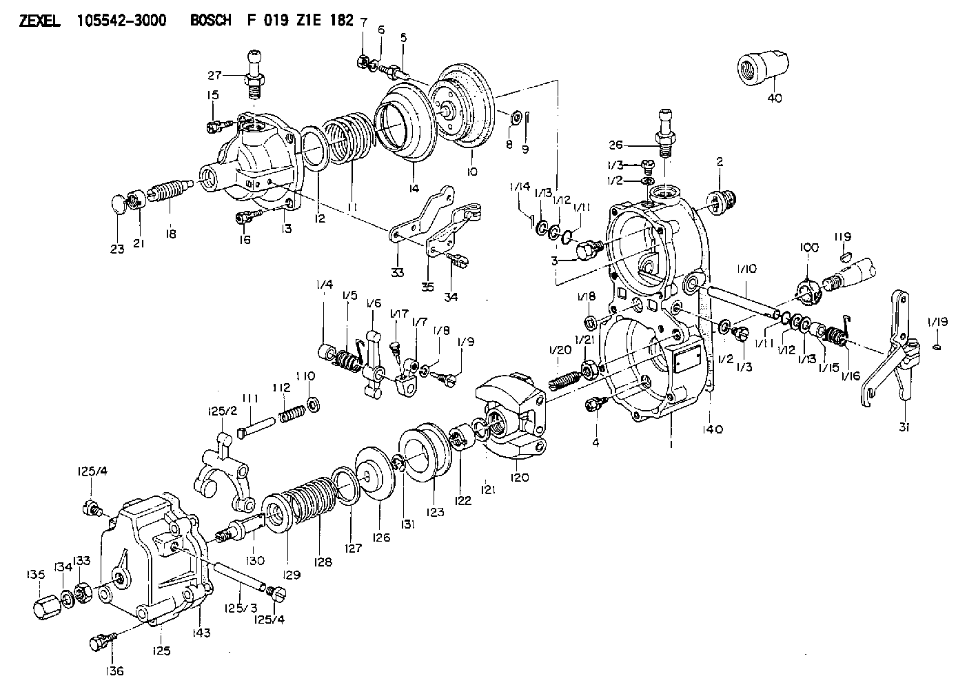
| 1. | [1] | 155014-7320 | GOVERNOR HOUSING |
| 1/1. | [1] | 155000-9110 | GOVERNOR HOUSING |
| 1/2. | [2] | 026506-1040 | GASKET D9.9&6.2T1 |
| 1/2. | [2] | 026506-1040 | GASKET D9.9&6.2T1 |
| 1/3. | [2] | 029010-6010 | CAPSULE M6P1.0L7 |
| 1/3. | [2] | 029010-6010 | CAPSULE M6P1.0L7 |
| 1/4. | [1] | 155052-7600 | BUSHING |
| 1/5. | [1] | 155005-0800 | COILED SPRING |
| 1/6. | [1] | 155003-1000 | CONTROL LEVER |
| 1/7. | [1] | 155003-1100 | CONTROL LEVER |
| 1/8. | [1] | 029320-6010 | LOCKING WASHER |
| 1/9. | [1] | 155411-8100 | FLAT-HEAD SCREW |
| 1/10. | [1] | 155004-2200 | LEVER SHAFT |
| 1/11. | [2] | 029630-8060 | O-RING |
| 1/11. | [2] | 029630-8060 | O-RING |
| 1/12. | [2] | 029300-8010 | PLAIN WASHER D15&8T1.00 |
| 1/12. | [2] | 029300-8010 | PLAIN WASHER D15&8T1.00 |
| 1/13. | [0] | 029310-8010 | PLAIN WASHER D15&8.4T0.2 |
| 1/13. | [0] | 029310-8010 | PLAIN WASHER D15&8.4T0.2 |
| 1/13. | [0] | 029310-8020 | PLAIN WASHER D15&8.4T0.3 |
| 1/14. | [1] | 025520-1210 | SPLIT PIN |
| 1/15. | [1] | 155052-7600 | BUSHING |
| 1/16. | [1] | 155005-0900 | COILED SPRING |
| 1/17. | [1] | 155006-0300 | BLEEDER SCREW |
| 1/18. | [1] | 029620-5010 | PACKING RING |
| 1/19. | [1] | 025802-1010 | WOODRUFF KEY |
| 1/20. | [1] | 155007-0520 | HEADLESS SCREW |
| 1/21. | [1] | 029241-0060 | UNION NUT |
| 2. | [1] | 154007-0200 | ADAPTOR |
| 3. | [1] | 020018-1840 | BLEEDER SCREW M8P1.25L18 |
| 4. | [4] | 029010-6810 | BLEEDER SCREW |
| 5. | [1] | 153406-0400 | BLEEDER SCREW |
| 6. | [1] | 014110-5440 | LOCKING WASHER |
| 7. | [1] | 013020-5220 | UNION NUT M5P0.8H4 |
| 8. | [1] | 023500-6210 | PLAIN WASHER D11&6.4T1.5 |
| 9. | [1] | 025520-1210 | SPLIT PIN |
| 10. | [1] | 155020-2920 | DIAPHRAGM |
| 11. | [1] | 155031-5800 | GOVERNOR SPRING |
| 12/1. | [0] | 155407-1100 | SHIM D37&30.5T0.5 |
| 12/1. | [0] | 155407-1200 | SHIM D37&30.5T1.0 |
| 12/1. | [0] | 155407-1300 | SHIM D37&30.5T1.5 |
| 12/1. | [0] | 155407-1400 | SHIM D37&30.5T2.0 |
| 12/1. | [0] | 155407-1500 | SHIM D37&30.5T2.5 |
| 12/1. | [0] | 155407-1600 | SHIM D37&30.5T3.0 |
| 12/1. | [0] | 155407-1700 | SHIM D37&30.5T0.2 |
| 12/1. | [0] | 155407-1800 | SHIM D37&30.5T0.3 |
| 13. | [1] | 155240-0500 | COVER |
| 15. | [3] | 020105-1640 | BLEEDER SCREW M5P0.8L16 |
| 16. | [1] | 029010-5350 | BLEEDER SCREW |
| 18. | [1] | 155241-3420 | HEADLESS SCREW |
| 21. | [1] | 155245-0100 | HEXAGON NUT |
| 23. | [1] | 029142-0010 | CAPSULE |
| 26. | [1] | 029721-2050 | JOINT CONNECTION |
| 27. | [1] | 029721-2050 | JOINT CONNECTION |
| 31. | [1] | 155414-7220 | CONTROL LEVER |
| 33. | [1] | 155402-2800 | PLATE |
| 34. | [2] | 029050-5040 | FLAT-HEAD SCREW M5P0.8L9 |
| 35. | [1] | 155418-0000 | CLAMPING BAND |
| 40. | [1] | 155404-5300 | CAP |
| 100. | [1] | 155412-5200 | IMPELLER WHEEL |
| 110. | [1] | 029300-5010 | PLAIN WASHER |
| 111/1. | [0] | 155411-0200 | STOP PIN L51 |
| 111/1. | [0] | 155411-0300 | STOP PIN L51.5 |
| 111/1. | [0] | 155411-0400 | STOP PIN L52 |
| 111/1. | [0] | 155411-7800 | STOP PIN L48.5 |
| 111/1. | [0] | 155411-7900 | STOP PIN L49.5 |
| 111/1. | [0] | 155411-8000 | STOP PIN L50.5 |
| 111/1. | [0] | 155411-9700 | STOP PIN L48 |
| 111/1. | [0] | 155411-9800 | STOP PIN L49 |
| 111/1. | [0] | 155411-9900 | STOP PIN L50 |
| 112. | [1] | 155411-8200 | COILED SPRING |
| 119. | [1] | 025803-1610 | WOODRUFF KEY |
| 120. | [1] | 154102-0720 | FLYWEIGHT ASSEMBLY |
| 121. | [1] | 029321-2020 | LOCKING WASHER |
| 122. | [1] | 029231-2030 | UNION NUT |
| 123. | [1] | 154123-0800 | SLIDING PIECE |
| 125. | [1] | 154405-4620 | COVER |
| 125/2. | [1] | 154406-2000 | FORK LINK |
| 125/3. | [1] | 154406-0500 | BEARING PIN |
| 125/4. | [2] | 029050-8050 | FLAT-HEAD SCREW |
| 125/4. | [2] | 029050-8050 | FLAT-HEAD SCREW |
| 126. | [1] | 154406-1700 | SLOTTED WASHER |
| 127. | [0] | 029302-3010 | SHIM D30&23T0.5 |
| 127B. | [0] | 029302-3020 | SHIM D30&23T1.0 |
| 128. | [1] | 155032-3400 | GOVERNOR SPRING |
| 128B. | [1] | 155032-3100 | GOVERNOR SPRING |
| 129. | [1] | 154406-1600 | SLOTTED WASHER |
| 130. | [1] | 154406-1100 | FLAT-HEAD SCREW |
| 131. | [1] | 016010-0740 | LOCKING WASHER |
| 133. | [1] | 023040-8040 | UNION NUT |
| 134. | [1] | 026508-1240 | GASKET D11.9&8.2T1 |
| 135. | [1] | 154035-0600 | CAP NUT |
| 136. | [5] | 029000-6810 | BLEEDER SCREW |
| 140. | [1] | 154390-0000 | GASKET |
| 143. | [1] | 154390-1000 | GASKET |
Include in #1:
101461-0390
as GOVERNOR
Cross reference number
Zexel num
Bosch num
Firm num
Name
105542-3000
F 019 Z1E 182
GOVERNOR
* K 14JP GOV RBD GOV
* K 14JP GOV RBD GOV
Information:
Adjustment of valve clearanceFuel System Bleeding
(1) Loosen the air vent plug of the fuel filter. (approx. 1.5 turns)(2) Move the priming pump for the filter up and down.(3) When fuel flowing from the vent hole no longer contains air bubbles, tighten the air vent plug.
Fuel system bleedingInspection and Adjustment of No-Load Minimum (Low Idling) Speed and Maximum Speed
(a) The following adjustments were inspected and set for each engine on the test bench at the factory, and the set bolts are sealed. These settings should be checked and adjusted only at our designated service shop.(b) After the governor parts are adjusted, all external stoppers must be sealed in the same way as when adjustments were made at the factory.(c) Whether the seals are intact or not has important bearing on the validity of claims under warranty. Be sure to seal all the specified sections.(d) When inspecting or adjusting, be ready to operate the engine stop lever manually in case the engine overruns (engine operation at extremely high speed).
Prior to inspection and adjustment, conduct a warm-up operation until the coolant and oil temperatures rise above 70 °C [158 °F].(1) Starting the engine(a) Pull the speed control lever toward the HIGH SPEED side, and operate the starter switch.(b) The engine ignites when the rotation speed reaches approximately 150 min-1, and the engine speed rises. Operate the speed control lever to maintain the engine speed between 800 and 1000 min-1.(c) After the engine speed stabilizes, return the speed control lever to the low idling position.
Inspection and adjustment of no-load minimum (low idling) speed and maximum speed(2) Low idling setting (no-load minimum rotation speed setting)Hold the speed control lever at the position of no-load minimum rotation speed, then secure the lever in that position using the idling adjustment screw.
If there is speed range which causes dangerous torsional vibration, avoid setting the engine speed in that range.
(3) Governor setting (maximum rotation speed setting)(a) Keep the speed control lever at the position of the specified maximum rotation speed.(b) With the speed control lever held in that position, adjust and set the governor set bolt (maximum rotation speed set screw) to the specified rotation speed).Inspection of V-Belt Tension
(1) Press the V-belt at a midpoint between the alternator and crankshaft pulley to check the mount of belt deflection.
Inspection of V-belt tension(2) If the amount of belt deflection does not conform to the standard value, loosen the adjusting bolt and move the alternator to adjust the belt tension.Engine Break-in Operation
When the engine is overhauled, it should be mounted on a dynamometer and operated for break-in and inspection.Starting Up
(1) Before starting the engine, check the levels of coolant, engine oil and fuel, and bleed the fuel and cooling system.(2) With the fuel supply cut off, operate the starter and crank the engine for about 15 seconds to circulate engine oil.(3) Move the speed control lever slightly in the direction for increased fuel (do not move it to "full injection" position), then turn the starter switch key to the [START]
Have questions with 105542-3000?
Group cross 105542-3000 ZEXEL
105542-3000
F 019 Z1E 182
GOVERNOR