Information governor
BOSCH
9 420 612 269
9420612269
ZEXEL
105490-5590
1054905590
MITSUBISHI
ME727212
me727212
Rating:
Scheme ###:
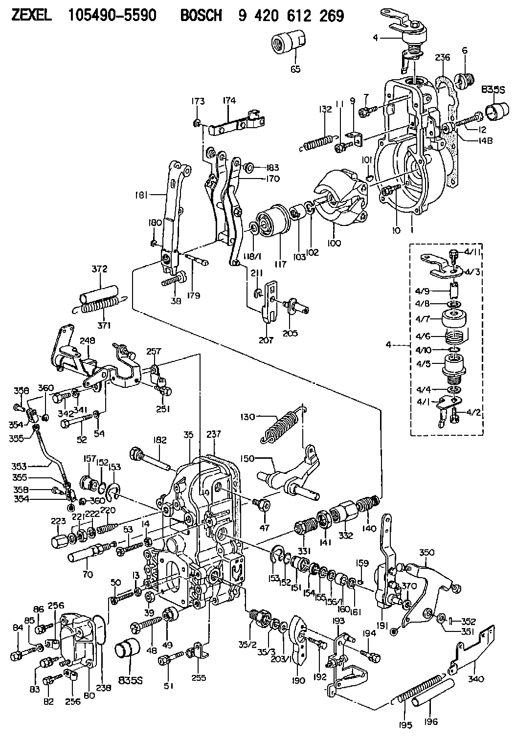
| 1. | [1] | 154000-8300 | GOVERNOR HOUSING |
| 4. | [1] | 154366-0120 | CONTROL LEVER |
| 4. | [1] | 154366-0120 | CONTROL LEVER |
| 4/1. | [1] | 154304-3500 | CONTROL LEVER |
| 4/2. | [1] | 154352-2000 | BLEEDER SCREW |
| 4/3. | [1] | 154366-0100 | CONTROL LEVER |
| 4/4. | [1] | 029311-0230 | SHIM D18&10.3T0.5 |
| 4/5. | [1] | 154321-1500 | BUSHING |
| 4/6. | [1] | 154327-4600 | COILED SPRING |
| 4/7. | [1] | 154322-0100 | CAP |
| 4/8. | [1] | 029311-0220 | SHIM D18&10.3T0.2 |
| 4/9. | [1] | 154324-2700 | LEVER SHAFT |
| 4/10. | [1] | 029631-0030 | O-RING &9.8W2.3 |
| 4/11. | [1] | 020006-1240 | BLEEDER SCREW M6P1L12 4T |
| 6. | [1] | 154007-0200 | ADAPTOR |
| 7. | [1] | 020018-1840 | BLEEDER SCREW M8P1.25L18 |
| 9. | [1] | 154350-1800 | PLATE |
| 10. | [5] | 029010-6810 | BLEEDER SCREW |
| 11. | [1] | 020106-1640 | BLEEDER SCREW M6P1.0L14 |
| 12. | [1] | 154013-0600 | BLEEDER SCREW |
| 13. | [1] | 013020-6040 | UNION NUT M6P1H5 |
| 14. | [1] | 013020-8040 | UNION NUT M8P1.25H7 |
| 14B. | [1] | 154011-2300 | UNION NUT |
| 35. | [1] | 154513-2320 | GOVERNOR COVER |
| 35/2. | [1] | 154321-1800 | BUSHING |
| 35/3. | [1] | 029621-0080 | PACKING RING |
| 38. | [1] | 154031-3500 | FLAT-HEAD SCREW |
| 39. | [1] | 154011-1600 | UNION NUT |
| 47. | [1] | 154036-1200 | CAPSULE |
| 48. | [1] | 154010-7100 | BLEEDER SCREW M10P1.25L47 |
| 48B. | [1] | 154010-7700 | BLEEDER SCREW M10P1.25L51 |
| 49. | [1] | 154011-2200 | UNION NUT |
| 50. | [1] | 155615-1600 | BLEEDER SCREW |
| 51. | [4] | 020106-3840 | BLEEDER SCREW |
| 52. | [2] | 029010-6850 | BLEEDER SCREW |
| 53. | [1] | 154010-7400 | BLEEDER SCREW M8P1.25L55 |
| 54. | [2] | 014110-6440 | LOCKING WASHER |
| 65. | [1] | 155404-3800 | CAP |
| 70. | [1] | 154055-0420 | HEADLESS SCREW |
| 80. | [1] | 154060-0020 | COVER |
| 82. | [1] | 029020-6210 | BLEEDER SCREW |
| 83. | [1] | 020006-1640 | BLEEDER SCREW M6P1L16 4T |
| 84. | [1] | 029020-6220 | BLEEDER SCREW |
| 85. | [1] | 014110-6440 | LOCKING WASHER |
| 86. | [1] | 020006-1640 | BLEEDER SCREW M6P1L16 4T |
| 100. | [1] | 154100-9520 | FLYWEIGHT ASSEMBLY |
| 101. | [1] | 025803-1610 | WOODRUFF KEY |
| 102. | [1] | 029321-2020 | LOCKING WASHER |
| 103. | [1] | 029231-2030 | UNION NUT |
| 117. | [1] | 154123-2320 | SLIDING PIECE |
| 118/1. | [0] | 029311-0010 | SHIM D14&10.1T0.2 |
| 118/1. | [0] | 029311-0180 | SHIM D14&10.1T0.3 |
| 118/1. | [0] | 029311-0190 | SHIM D14&10.1T0.40 |
| 118/1. | [0] | 029311-0210 | SHIM D14&10.1T1 |
| 118/1. | [0] | 139410-0000 | SHIM D14.0&10.1T0.5 |
| 118/1. | [0] | 139410-0100 | SHIM D14.0&10.1T1.5 |
| 118/1. | [0] | 139410-3000 | SHIM D14&10.1T2.0 |
| 118/1. | [0] | 139410-3100 | SHIM D14&10.1T3.0 |
| 118/1. | [0] | 139410-3200 | SHIM D14&10.1T4.0 |
| 130. | [1] | 154150-6200 | GOVERNOR SPRING |
| 132. | [1] | 154154-0701 | COILED SPRING |
| 140. | [1] | 154180-1920 | HEADLESS SCREW |
| 141. | [1] | 029201-6010 | UNION NUT |
| 150. | [1] | 154200-3801 | SWIVELLING LEVER |
| 151. | [1] | 154204-2001 | BUSHING |
| 152. | [2] | 029631-8020 | O-RING |
| 152. | [2] | 029631-8020 | O-RING |
| 153. | [2] | 154354-3900 | LOCKING WASHER |
| 153. | [2] | 154354-3900 | LOCKING WASHER |
| 154. | [1] | 139611-0000 | PACKING RING |
| 155. | [1] | 139411-0000 | SHIM |
| 156/1. | [0] | 029311-1110 | SHIM D17&11T0.1 |
| 156/1. | [0] | 029311-1120 | SHIM D17&11T0.2 |
| 156/1. | [0] | 029311-1130 | SHIM D17&11T0.3 |
| 157. | [1] | 154204-3400 | BUSHING |
| 159. | [1] | 025803-1310 | WOODRUFF KEY |
| 160. | [1] | 154206-0900 | BUSHING |
| 161. | [0] | 154206-0200 | PLAIN WASHER D19.5&11.2T1.0 |
| 170. | [1] | 154216-2620 | FORK LEVER |
| 173. | [1] | 016010-0540 | LOCKING WASHER |
| 174. | [1] | 154230-4720 | STRAP |
| 179. | [1] | 154238-0301 | BEARING PIN |
| 180. | [1] | 016010-0540 | LOCKING WASHER |
| 181. | [1] | 154236-5300 | TENSIONING LEVER |
| 182. | [1] | 154237-0900 | BEARING PIN |
| 183. | [2] | 154237-0600 | BUSHING |
| 190. | [1] | 154360-2800 | CONTROL LEVER |
| 191. | [1] | 154349-2820 | CONTROL LEVER |
| 192. | [1] | 020006-1670 | BLEEDER SCREW M6P1L16 7T |
| 193. | [1] | 154363-5220 | CONTROL LEVER |
| 194. | [2] | 020006-1240 | BLEEDER SCREW M6P1L12 4T |
| 195. | [1] | 154317-2300 | COILED SPRING |
| 196. | [1] | 154156-0500 | TUBE |
| 203/1. | [0] | 029311-0640 | SHIM D26.0&10.2T0.95 |
| 203/1. | [0] | 029311-0650 | SHIM D26.0&10.2T0.20 |
| 203/1. | [0] | 029311-0660 | SHIM D26.0&10.2T0.25 |
| 203/1. | [0] | 029311-0670 | SHIM D26.0&10.2T0.30 |
| 203/1. | [0] | 029311-0680 | SHIM D26.0&10.2T0.35 |
| 203/1. | [0] | 029311-0690 | SHIM D26.0&10.2T0.40 |
| 203/1. | [0] | 029311-0700 | SHIM D26.0&10.2T0.50 |
| 203/1. | [0] | 139410-1400 | SHIM D26&10.2T0.7 |
| 203/1. | [0] | 139410-1500 | SHIM D26&10.2T0.9 |
| 203/1. | [0] | 139410-1600 | SHIM D26&10.2T0.8 |
| 203/1. | [0] | 139410-2700 | SHIM D26&10.2T0.6 |
| 205. | [1] | 154324-4500 | LEVER SHAFT |
| 207. | [1] | 154326-0300 | CONTROL LEVER |
| 211. | [1] | 016010-0840 | LOCKING WASHER |
| 220. | [1] | 154050-1220 | HEADLESS SCREW |
| 221. | [1] | 029201-2130 | UNION NUT M12P1.0H6 |
| 222. | [2] | 026512-1540 | GASKET D15.4&12.2T1.50 |
| 223. | [1] | 154159-1200 | CAP NUT |
| 236. | [1] | 154390-0000 | GASKET |
| 237. | [1] | 154390-0300 | GASKET |
| 238. | [1] | 029635-2020 | O-RING |
| 248. | [1] | 154372-5520 | BRACKET |
| 251. | [1] | 020006-1240 | BLEEDER SCREW M6P1L12 4T |
| 255. | [1] | 154614-4020 | CLAMPING BAND |
| 256. | [2] | 154614-4120 | CLAMPING BAND |
| 256. | [2] | 154614-4120 | CLAMPING BAND |
| 257. | [1] | 154614-4220 | CLAMPING BAND |
| 331. | [1] | 154185-1020 | HEADLESS SCREW |
| 332. | [1] | 029201-6220 | UNION NUT |
| 340. | [1] | 154213-5800 | BRACKET |
| 341. | [1] | 014110-8440 | LOCKING WASHER |
| 342. | [1] | 010038-1640 | BLEEDER SCREW M8P1.25L16 |
| 350. | [1] | 154370-0620 | CONTROL LEVER |
| 351. | [1] | 014010-6140 | PLAIN WASHER D13&6.5T1 |
| 352. | [1] | 015316-1090 | SPLIT PIN |
| 353. | [1] | 154359-5700 | STOP PIN |
| 354. | [2] | 154352-6100 | CLEVIS |
| 354. | [2] | 154352-6100 | CLEVIS |
| 355. | [2] | 013020-6040 | UNION NUT M6P1H5 |
| 355. | [2] | 013020-6040 | UNION NUT M6P1H5 |
| 358. | [2] | 154604-2400 | BEARING PIN |
| 358. | [2] | 154604-2400 | BEARING PIN |
| 360. | [2] | 016010-0640 | LOCKING WASHER |
| 360. | [2] | 016010-0640 | LOCKING WASHER |
| 370. | [0] | 029310-8650 | SHIM D10.5&8.5T0.5 |
| 371. | [1] | 154317-6300 | COILED SPRING |
| 372. | [1] | 154156-2300 | TUBE |
| 835S. | [2] | 154062-1700 | CAP D20L32 |
| 835S. | [2] | 154062-1700 | CAP D20L32 |
Include in #1:
101607-1170
as GOVERNOR
Cross reference number
Zexel num
Bosch num
Firm num
Name
105490-5590
ME727212 MITSUBISHI
GOVERNOR
K 14JN MECHANICAL GOVERNOR GOV RFD GOV
K 14JN MECHANICAL GOVERNOR GOV RFD GOV
Information:
Starter Motor - Model - CA45
General Description
Designed for flange mounting, the C.A.45 starter motor has a uniform cylindrical shape with no surface protrusion. This is because the solenoid and main switch assemblies are housed within the drive end-shield, around (i.e., co-axially with) the armature shaft.The essential feature of the co-axial starter is that, the pinion alone moves axially to engage the engine flywheel. There is no longitudinal movement of the whole armature assembly, as in the axial types.Smooth engagement of the pinion with the engine flywheel is constantly ensured by using two-stage operation of the solenoid and switch mechanisms. Thus the risk of damage to both pinion and flywheel, through faulty meshing, is practically eliminated.In construction, the starter consists of three main sections, into which it can be easily dismantled.1. The solenoid switch-gear and pinion assembly housed in the drive end-shield.2. The armature, shaft and commutator assembly.3. The yoke, pole-piece and field-coil assembly.Ready access is possible therefore, to those parts most likely to require adjustment, such as the switchgear and commutator assemblies.The starter is designed for working off a 12 volt supply, with 17 amps solenoid current.Testing on the Vehicle
Ensure that the battery is in a charged condition.Switch on the lamps and operate the starter button. If the starter fails to function, but the lights maintain full brilliance, check the switch and battery connections to the starter and all external leads. Sluggish action of the starter can be caused by a poor or faulty connection.Difficulty in smooth engagement between starter and engine flywheel is probably due to dirt on the starter-shaft helices preventing free pinion movement. The shaft should be thoroughly cleaned with kerosene followed by the application of a small quantity of Caltex Thuben 90 or SAE 90 oil.Operating the Starter
When starting the engine the following points should be rigidly observed
1. Press the starter button firmly and release it immediately the engine fires.2. If the engine does not fire at once, let it come to rest before pressing the switch again.3. Do not run the battery down by keeping the starter switch pressed when the engine refuses to start. Ascertain the cause.4. On some engines it is often helpful to depress the clutch when starting.5. Do not operate the starter when the engine is running as serious damage may occur to both starter and flywheel.Maintenance
Lubrication
The large oil reservoir in the drive end shield need only be replenished during overhaul periods, when a supply of Shelltella T27 or BP Energol SHF 100 oil should be added through the oil plug.An oil impregnated sintered bronze bush is fitted at the commutator end, and needs no further attention.Brush Gear and Commutator
Inspect the brushes at intervals of approximately 500 hours. See that they are free in their guides and that the leads are quite free for movement, by easing back the brush springs and pulling gently on the flexible connections. If a brush is inclined to stick, remove it from its holder and clean the sides with a petrol moistened cloth.Be