Information governor
BOSCH
F 019 Z3E 871
f019z3e871
ZEXEL
105490-5530
1054905530
MITSUBISHI
ME726497
me726497
Rating:
Scheme ###:
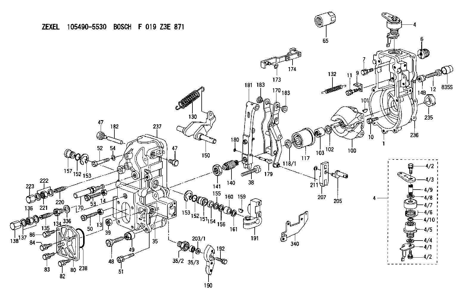
| 1. | [1] | 154004-0800 | GOVERNOR HOUSING |
| 4. | [1] | 154380-0820 | CONTROL LEVER |
| 4. | [1] | 154380-0820 | CONTROL LEVER |
| 4/1. | [1] | 154304-3500 | CONTROL LEVER |
| 4/2. | [2] | 154352-2000 | BLEEDER SCREW |
| 4/2. | [2] | 154352-2000 | BLEEDER SCREW |
| 4/3. | [1] | 154364-2600 | CONTROL LEVER |
| 4/4. | [1] | 029311-0230 | SHIM D18&10.3T0.5 |
| 4/5. | [1] | 154321-1500 | BUSHING |
| 4/6. | [1] | 154327-3500 | COILED SPRING |
| 4/7. | [1] | 154322-0100 | CAP |
| 4/8. | [1] | 029311-0220 | SHIM D18&10.3T0.2 |
| 4/9. | [1] | 154324-2700 | LEVER SHAFT |
| 4/10. | [1] | 029631-0050 | O-RING |
| 6. | [1] | 154007-0200 | ADAPTOR |
| 7. | [1] | 020018-1840 | BLEEDER SCREW M8P1.25L18 |
| 9. | [1] | 154350-1800 | PLATE |
| 10. | [5] | 029010-6810 | BLEEDER SCREW |
| 11. | [1] | 020106-1640 | BLEEDER SCREW M6P1.0L14 |
| 12. | [1] | 154010-8100 | BLEEDER SCREW M8P1.25L65 |
| 13. | [1] | 029240-6010 | UNION NUT M6P1.0H5* |
| 14. | [1] | 154011-0100 | HEXAGON NUT |
| 14B. | [1] | 154011-2300 | UNION NUT |
| 35. | [1] | 154515-1520 | GOVERNOR COVER |
| 35/2. | [1] | 154321-2000 | BUSHING |
| 35/3. | [1] | 139610-0000 | PACKING RING |
| 38. | [1] | 154031-3401 | FLAT-HEAD SCREW |
| 39. | [1] | 029201-0160 | UNION NUT |
| 47. | [2] | 154036-1800 | CAPSULE |
| 47. | [2] | 154036-1800 | CAPSULE |
| 48. | [1] | 154010-5500 | BLEEDER SCREW M10P1.25L42 |
| 49. | [1] | 154011-2100 | UNION NUT |
| 50. | [1] | 155615-1900 | BLEEDER SCREW |
| 51. | [5] | 020106-4540 | BLEEDER SCREW M6P1.0L45 |
| 52. | [2] | 029010-6850 | BLEEDER SCREW |
| 53. | [1] | 154010-2900 | BLEEDER SCREW |
| 54. | [2] | 014110-6440 | LOCKING WASHER |
| 65. | [1] | 155404-3800 | CAP |
| 70. | [1] | 154055-0320 | HEADLESS SCREW |
| 80. | [1] | 154063-3120 | COVER |
| 82. | [1] | 029020-6210 | BLEEDER SCREW |
| 83. | [1] | 020006-1640 | BLEEDER SCREW M6P1L16 4T |
| 84. | [1] | 029020-6210 | BLEEDER SCREW |
| 86. | [1] | 020006-1640 | BLEEDER SCREW M6P1L16 4T |
| 100. | [1] | 154100-9320 | FLYWEIGHT ASSEMBLY |
| 101. | [1] | 025803-1610 | WOODRUFF KEY |
| 102. | [1] | 029321-2020 | LOCKING WASHER |
| 103. | [1] | 139212-0000 | UNION NUT |
| 117. | [1] | 154123-2720 | SLIDING PIECE |
| 118/1. | [0] | 029311-0010 | SHIM D14&10.1T0.2 |
| 118/1. | [0] | 029311-0180 | SHIM D14&10.1T0.3 |
| 118/1. | [0] | 029311-0190 | SHIM D14&10.1T0.40 |
| 118/1. | [0] | 029311-0210 | SHIM D14&10.1T1 |
| 118/1. | [0] | 139410-0000 | SHIM D14.0&10.1T0.5 |
| 118/1. | [0] | 139410-0100 | SHIM D14.0&10.1T1.5 |
| 118/1. | [0] | 139410-3000 | SHIM D14&10.1T2.0 |
| 118/1. | [0] | 139410-3100 | SHIM D14&10.1T3.0 |
| 118/1. | [0] | 139410-3200 | SHIM D14&10.1T4.0 |
| 130. | [1] | 154150-7900 | GOVERNOR SPRING |
| 132. | [1] | 154154-0701 | COILED SPRING |
| 134. | [1] | 154370-3000 | ADAPTOR |
| 135. | [1] | 154158-0920 | HEADLESS SCREW |
| 136. | [1] | 029201-2130 | UNION NUT M12P1.0H6 |
| 137. | [2] | 026512-1540 | GASKET D15.4&12.2T1.50 |
| 138. | [1] | 154159-1200 | CAP NUT |
| 140. | [1] | 154180-3520 | HEADLESS SCREW |
| 141. | [1] | 139218-0100 | UNION NUT |
| 150. | [1] | 154200-5701 | SWIVELLING LEVER |
| 151. | [1] | 154200-5501 | BUSHING |
| 152. | [2] | 139700-0000 | O-RING |
| 152. | [2] | 139700-0000 | O-RING |
| 153. | [2] | 154354-3900 | LOCKING WASHER |
| 153. | [2] | 154354-3900 | LOCKING WASHER |
| 154. | [1] | 139610-0201 | PACKING RING |
| 155. | [1] | 139411-0100 | SHIM D22.0&12.0T0.40 |
| 156. | [0] | 139411-0200 | SHIM D18.0&12.0T0.10 |
| 156B. | [0] | 139411-0300 | SHIM D18.0&12.0T0.20 |
| 156C. | [0] | 139411-0400 | SHIM D18.0&12.0T0.30 |
| 157. | [1] | 154204-3500 | BUSHING |
| 159. | [1] | 025803-1310 | WOODRUFF KEY |
| 160. | [1] | 154206-2300 | BUSHING |
| 161. | [0] | 154206-2400 | PLAIN WASHER D20.5&12.2T1 |
| 170. | [1] | 154216-3020 | FORK LEVER |
| 173. | [1] | 016010-0540 | LOCKING WASHER |
| 174. | [1] | 154230-6820 | STRAP |
| 179. | [1] | 154238-0201 | BEARING PIN |
| 180. | [1] | 016010-0540 | LOCKING WASHER |
| 181. | [1] | 154236-5200 | TENSIONING LEVER |
| 182. | [1] | 154237-1200 | BEARING PIN |
| 183. | [2] | 154237-1300 | BUSHING |
| 183. | [2] | 154237-1300 | BUSHING |
| 190. | [1] | 154360-2800 | CONTROL LEVER |
| 191. | [1] | 154340-1920 | CONTROL LEVER |
| 192. | [1] | 020006-1670 | BLEEDER SCREW M6P1L16 7T |
| 203/1. | [0] | 029311-0640 | SHIM D26.0&10.2T0.95 |
| 203/1. | [0] | 029311-0650 | SHIM D26.0&10.2T0.20 |
| 203/1. | [0] | 029311-0660 | SHIM D26.0&10.2T0.25 |
| 203/1. | [0] | 029311-0670 | SHIM D26.0&10.2T0.30 |
| 203/1. | [0] | 029311-0680 | SHIM D26.0&10.2T0.35 |
| 203/1. | [0] | 029311-0690 | SHIM D26.0&10.2T0.40 |
| 203/1. | [0] | 029311-0700 | SHIM D26.0&10.2T0.50 |
| 203/1. | [0] | 139410-1400 | SHIM D26&10.2T0.7 |
| 203/1. | [0] | 139410-1500 | SHIM D26&10.2T0.9 |
| 203/1. | [0] | 139410-1600 | SHIM D26&10.2T0.8 |
| 203/1. | [0] | 139410-2700 | SHIM D26&10.2T0.6 |
| 205. | [1] | 154324-4100 | LEVER SHAFT |
| 207. | [1] | 154326-0300 | CONTROL LEVER |
| 211. | [1] | 016010-0840 | LOCKING WASHER |
| 220. | [1] | 154050-1220 | HEADLESS SCREW |
| 221. | [1] | 029201-2130 | UNION NUT M12P1.0H6 |
| 222. | [2] | 026512-1540 | GASKET D15.4&12.2T1.50 |
| 223. | [1] | 154159-1200 | CAP NUT |
| 235. | [1] | 155412-5800 | IMPELLER WHEEL |
| 236. | [1] | 154390-0000 | GASKET |
| 237. | [1] | 154390-0200 | GASKET |
| 238. | [1] | 139700-0100 | O-RING |
| 336. | [1] | 029331-6030 | GASKET |
| 340. | [1] | 154213-5800 | BRACKET |
| 835S. | [1] | 154062-1700 | CAP D20L32 |
Include in #1:
101606-6660
as GOVERNOR
Cross reference number
Zexel num
Bosch num
Firm num
Name
105490-5530
ME726497 MITSUBISHI
GOVERNOR
K 14JN MECHANICAL GOVERNOR GOV RFD GOV
K 14JN MECHANICAL GOVERNOR GOV RFD GOV
Information:
* Select an appropriate cleaning method according to the condition of the cooling system as shown below.
* FUSO DIESEL LONGLIFE COOLANT is flammable. Keep them away from heat and flames.
* If you accidentally splash FUSO DIESEL LONGLIFE COOLANT, FUSO ANTIFREEZE, OR RADIATOR ANTIRUST (RADIPET 9) in your eyes, wash it out immediately with water and seek medical attention.
Air Bleeding of Cooling System
* With the pressure cap removed and the coolant temperature at 90°C, let the engine idle in order to bleed air completely out of the cooling system.* After air bleeding is completed, refill the reservoir tank with coolant as needed.Air/Gas Leakage Test
* Presence of air or exhaust gas in coolant accelerates corrosion of the cooling system components. To prevent this, carry out air/gas leakage tests in accordance with the following procedure.* Remove the pressure cap.
* If the engine is hot, boiling coolant may spurt out from the filler port when the pressure cap is loosened. To avoid being scold, make sure to remove the pressure cap only when the coolant is cold.
* Run the engine until the coolant temperature rises to approximately 90°C. * If air bubbles appear continuously through the filler port, there is air or exhaust gas penetrating into the cooling system.* Presence of air in coolant can be an indication of loose cylinder head bolts, loose water pump mounting bolts, loose hose connections, and/or a damaged hose.* Presence of exhaust gas in coolant can be an indication of a damaged cylinder head gasket and/or cracks in the cylinder head.Inspection of Coolant Leak
* With the engine idling, check the coolant passage (radiator hose, water hose, etc.) for coolant leak.* If any leak is found, check the installation condition of each part and retighten the loose part to the specified torque.If any crack or damage is found on a pipe or hose, replace it to a new one.Coolant Fan, Belt And Water Pump
Removal Sequence1 Cooling fan2 Fan spacer3 Belt4 Water pump pulley5 Water pump6 O-ringX: Non-reusable parts* The water pump cannot be disassembled. It must be replaced if defective. Installation SequenceFollow the removal sequence in reverse.
* The water pump pulley is driven by two belts. Always replace the two belts simultaneously to ensure that both belts have the same tension.* Make sure that there is no oil or grease on the belts. Belts soiled with oil or grease may easily slip, resulting in deteriorated performance of the cooling system.* Keep the O-ring free from engine oil. Engine oil will make the O-ring swell, which may cause leakage.
* After installation, check and adjust the belt tension. (See "GENERAL INSPECTION AND ADJUSTMENT".)Lubricant and/or sealant Water Hose And Pipe
Disassembly Sequence1 Heater return pipe2 O-ring3 Water temperature sensor4 Water outlet pipe5 Gasket*a: Thermostat caseX: Non-reusable parts Assembly SequenceFollow the disassembly sequence in reverse.
* Keep the O-ring free of engine oil. Engine oil will make the O-ring swell, which may cause leakage.
Tightening Torque (Unit: N m {kgf m}) Lubricant and/or sealant Thermostat
Disassembly Sequence1 Thermostat cover2 Thermostat3 Bypass Pipe4 O-ring5 Thermostat