Information governor
BOSCH
9 420 612 268
9420612268
ZEXEL
105490-5520
1054905520
MITSUBISHI
ME726418
me726418

Rating:
Scheme ###:
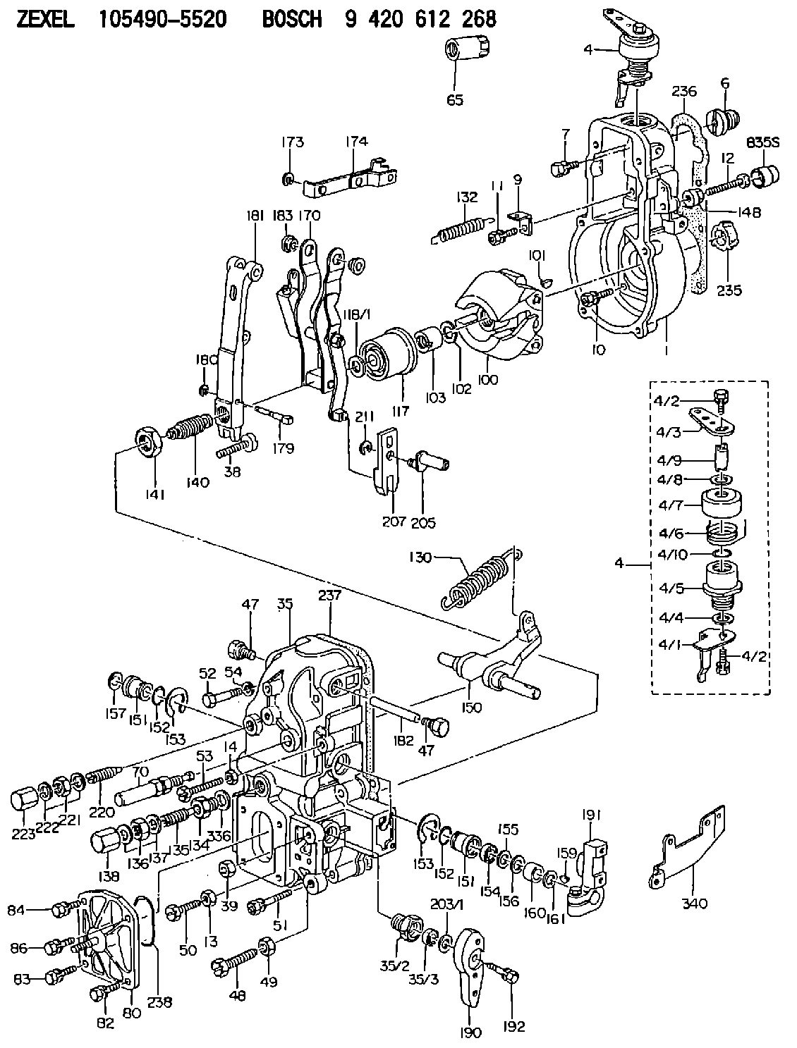
| 1. | [1] | 154004-0800 | GOVERNOR HOUSING |
| 4. | [1] | 154364-2620 | CONTROL LEVER |
| 4. | [1] | 154364-2620 | CONTROL LEVER |
| 4/1. | [1] | 154304-3500 | CONTROL LEVER |
| 4/2. | [2] | 154352-2000 | BLEEDER SCREW |
| 4/2. | [2] | 154352-2000 | BLEEDER SCREW |
| 4/3. | [1] | 154364-2600 | CONTROL LEVER |
| 4/4. | [1] | 029311-0230 | SHIM D18&10.3T0.5 |
| 4/5. | [1] | 154321-1500 | BUSHING |
| 4/6. | [1] | 154327-3500 | COILED SPRING |
| 4/7. | [1] | 154322-0100 | CAP |
| 4/8. | [1] | 029311-0220 | SHIM D18&10.3T0.2 |
| 4/9. | [1] | 154324-2700 | LEVER SHAFT |
| 4/10. | [1] | 029631-0030 | O-RING &9.8W2.3 |
| 6. | [1] | 154007-0200 | ADAPTOR |
| 7. | [1] | 020018-1840 | BLEEDER SCREW M8P1.25L18 |
| 9. | [1] | 154350-1800 | PLATE |
| 10. | [5] | 029010-6810 | BLEEDER SCREW |
| 11. | [1] | 020106-1640 | BLEEDER SCREW M6P1.0L14 |
| 12. | [1] | 154010-8100 | BLEEDER SCREW M8P1.25L65 |
| 13. | [1] | 029240-6010 | UNION NUT M6P1.0H5* |
| 14. | [1] | 154011-0100 | HEXAGON NUT |
| 14B. | [1] | 154011-2300 | UNION NUT |
| 35. | [1] | 154515-0120 | GOVERNOR COVER |
| 35/2. | [1] | 154321-2000 | BUSHING |
| 35/3. | [1] | 029621-0080 | PACKING RING |
| 38. | [1] | 154031-3401 | FLAT-HEAD SCREW |
| 39. | [1] | 029201-0160 | UNION NUT |
| 47. | [2] | 154036-1800 | CAPSULE |
| 47. | [2] | 154036-1800 | CAPSULE |
| 48. | [1] | 154010-5500 | BLEEDER SCREW M10P1.25L42 |
| 49. | [1] | 154011-2100 | UNION NUT |
| 50. | [1] | 155615-1900 | BLEEDER SCREW |
| 51. | [5] | 020106-4540 | BLEEDER SCREW M6P1.0L45 |
| 52. | [2] | 029010-6850 | BLEEDER SCREW |
| 53. | [1] | 154010-2900 | BLEEDER SCREW |
| 54. | [2] | 014110-6440 | LOCKING WASHER |
| 65. | [1] | 155404-3800 | CAP |
| 70. | [1] | 154055-0320 | HEADLESS SCREW |
| 80. | [1] | 154063-3120 | COVER |
| 82. | [1] | 029020-6210 | BLEEDER SCREW |
| 83. | [1] | 020006-1640 | BLEEDER SCREW M6P1L16 4T |
| 84. | [1] | 029020-6210 | BLEEDER SCREW |
| 86. | [1] | 020006-1640 | BLEEDER SCREW M6P1L16 4T |
| 100. | [1] | 154100-9320 | FLYWEIGHT ASSEMBLY |
| 101. | [1] | 025803-1610 | WOODRUFF KEY |
| 102. | [1] | 029321-2020 | LOCKING WASHER |
| 103. | [1] | 139212-0000 | UNION NUT |
| 117. | [1] | 154123-2320 | SLIDING PIECE |
| 118/1. | [0] | 029311-0010 | SHIM D14&10.1T0.2 |
| 118/1. | [0] | 029311-0180 | SHIM D14&10.1T0.3 |
| 118/1. | [0] | 029311-0190 | SHIM D14&10.1T0.40 |
| 118/1. | [0] | 029311-0210 | SHIM D14&10.1T1 |
| 118/1. | [0] | 139410-0000 | SHIM D14.0&10.1T0.5 |
| 118/1. | [0] | 139410-0100 | SHIM D14.0&10.1T1.5 |
| 118/1. | [0] | 139410-3000 | SHIM D14&10.1T2.0 |
| 118/1. | [0] | 139410-3100 | SHIM D14&10.1T3.0 |
| 118/1. | [0] | 139410-3200 | SHIM D14&10.1T4.0 |
| 130. | [1] | 154150-7900 | GOVERNOR SPRING |
| 132. | [1] | 154154-0701 | COILED SPRING |
| 134. | [1] | 154370-3000 | ADAPTOR |
| 135. | [1] | 154158-0920 | HEADLESS SCREW |
| 136. | [1] | 029201-2130 | UNION NUT M12P1.0H6 |
| 137. | [2] | 026512-1540 | GASKET D15.4&12.2T1.50 |
| 138. | [1] | 154159-1200 | CAP NUT |
| 140. | [1] | 154180-3520 | HEADLESS SCREW |
| 141. | [1] | 139218-0100 | UNION NUT |
| 150. | [1] | 154200-5701 | SWIVELLING LEVER |
| 151. | [1] | 154200-5501 | BUSHING |
| 151. | [1] | 154200-5501 | BUSHING |
| 152. | [2] | 139700-0000 | O-RING |
| 152. | [2] | 139700-0000 | O-RING |
| 153. | [2] | 154354-3900 | LOCKING WASHER |
| 153. | [2] | 154354-3900 | LOCKING WASHER |
| 154. | [1] | 139610-0101 | PACKING RING |
| 155. | [1] | 139411-0100 | SHIM D22.0&12.0T0.40 |
| 156. | [0] | 139411-0200 | SHIM D18.0&12.0T0.10 |
| 156B. | [0] | 139411-0300 | SHIM D18.0&12.0T0.20 |
| 156C. | [0] | 139411-0400 | SHIM D18.0&12.0T0.30 |
| 157. | [1] | 154204-3500 | BUSHING |
| 159. | [1] | 025803-1310 | WOODRUFF KEY |
| 160. | [1] | 154206-2300 | BUSHING |
| 161. | [0] | 154206-2400 | PLAIN WASHER D20.5&12.2T1 |
| 170. | [1] | 154216-3020 | FORK LEVER |
| 173. | [1] | 016010-0540 | LOCKING WASHER |
| 174. | [1] | 154230-6820 | STRAP |
| 179. | [1] | 154238-0201 | BEARING PIN |
| 180. | [1] | 016010-0540 | LOCKING WASHER |
| 181. | [1] | 154236-5200 | TENSIONING LEVER |
| 182. | [1] | 154237-1200 | BEARING PIN |
| 183. | [2] | 154237-1300 | BUSHING |
| 190. | [1] | 154360-2800 | CONTROL LEVER |
| 191. | [1] | 154340-1920 | CONTROL LEVER |
| 192. | [1] | 020006-1670 | BLEEDER SCREW M6P1L16 7T |
| 203/1. | [0] | 029311-0640 | SHIM D26.0&10.2T0.95 |
| 203/1. | [0] | 029311-0650 | SHIM D26.0&10.2T0.20 |
| 203/1. | [0] | 029311-0660 | SHIM D26.0&10.2T0.25 |
| 203/1. | [0] | 029311-0670 | SHIM D26.0&10.2T0.30 |
| 203/1. | [0] | 029311-0680 | SHIM D26.0&10.2T0.35 |
| 203/1. | [0] | 029311-0690 | SHIM D26.0&10.2T0.40 |
| 203/1. | [0] | 029311-0700 | SHIM D26.0&10.2T0.50 |
| 203/1. | [0] | 139410-1400 | SHIM D26&10.2T0.7 |
| 203/1. | [0] | 139410-1500 | SHIM D26&10.2T0.9 |
| 203/1. | [0] | 139410-1600 | SHIM D26&10.2T0.8 |
| 203/1. | [0] | 139410-2700 | SHIM D26&10.2T0.6 |
| 205. | [1] | 154324-4100 | LEVER SHAFT |
| 207. | [1] | 154326-0300 | CONTROL LEVER |
| 211. | [1] | 016010-0840 | LOCKING WASHER |
| 220. | [1] | 154050-1220 | HEADLESS SCREW |
| 221. | [1] | 029201-2130 | UNION NUT M12P1.0H6 |
| 222. | [2] | 026512-1540 | GASKET D15.4&12.2T1.50 |
| 223. | [1] | 154159-1200 | CAP NUT |
| 235. | [1] | 155412-5300 | IMPELLER WHEEL |
| 236. | [1] | 154390-0000 | GASKET |
| 237. | [1] | 154390-0200 | GASKET |
| 238. | [1] | 139700-0100 | O-RING |
| 336. | [1] | 029331-6030 | GASKET |
| 340. | [1] | 154213-5800 | BRACKET |
| 835S. | [1] | 154062-1700 | CAP D20L32 |
Cross reference number
Zexel num
Bosch num
Firm num
Name
105490-5520
ME726418 MITSUBISHI
GOVERNOR
K 14JN MECHANICAL GOVERNOR GOV RFD GOV
K 14JN MECHANICAL GOVERNOR GOV RFD GOV
Information:
* Remove any carbon deposits from the injection nozzles before disassembling, assembling, or adjusting the injection nozzle assembly. Before disassembling, check the pressure and shape of the spray and inspect the assembly for fuel leakage. Do not disassemble if no defects are evident.* Do not change the needle valve and nozzle combination on each cylinder.
* Assembly sequenceFollow the disassembly sequence in reverse.Service standards Tightening torque (Unit: N m {kgf m}) Special tools (Unit: mm) Inspection before removal
Inspection: Injection nozzle* Connect the injection nozzle to the nozzle tester and carry out the following inspections.
* Before starting the inspections, operate the lever on the nozzle tester two or three times to bleed out all the air.
(1) Checking the valve opening pressure* Push down the lever on the nozzle tester at a rate of one to two seconds per stroke. This will cause the pressure gauge reading to rise gradually, and the needle will suddenly deflect. Note the pressure at which the needle starts to deflect. * If the measurement is out of the standard value range, disassemble the nozzle, clean it, and then adjust it using an adjusting shim.* Available adjusting shims (thickness): 1.2 mm to 1.7 mm (11 different thicknesses in increments of 0.05 mm)* If the valve opening pressure is still incorrect after the adjustment, replace the injection nozzle assembly.
* Do not touch the spray that comes out of the nozzle.
(2) Inspecting the spray condition * Pump the lever on the nozzle at a rate of about one to two seconds per stroke and keep it spraying continuously.A Spray in the form of straight line (Good: spray angle at 10° or less)B Spray angle too large (Bad)C Spray deviates from centerline (Bad)D Irregular spray (Bad)
* Do not touch the spray that comes out of the nozzle.
* Check that no fuel drips from the nozzle after the spray is complete.* If defects are evident, disassemble and clean the injection nozzle, and then inspect its spray condition once again.* If defects persist after reinspection, replace the injection nozzle assembly.(3) Checking for leakage * Decrease the nozzle pressure to a pressure 1960 kPa {20 kgf/cm2} lower than the first valve opening pressure. Maintain this pressure for 10 seconds and check that no fuel drips from the end of the nozzle.* If fuel drips are evident, disassemble and clean the injection nozzle, and then perform a leakage test once again.* If leakage is detected during the reinspection, replace the injection nozzle assembly.Removal procedure
Removal: Injection nozzle
* Do not touch the sliding surfaces of the needle valve. If you accidentally touch it, clean it with a cleaning fluid (such as gas oil).* Do not change the needle valve and nozzle combination on each cylinder.
Cleaning procedure
Cleaning: Injection nozzle* Wash the needle valve and nozzle in a cleaning fluid (such as gas oil), then use
to remove any carbon deposits according to the following procedure. * Remove carbon deposits from the tip of the needle valve using the clean bar of
.
* Do not use a wire brush