Information governor
BOSCH
9 420 611 018
9420611018
ZEXEL
105490-5510
1054905510
MITSUBISHI
ME726394
me726394
Rating:
Scheme ###:
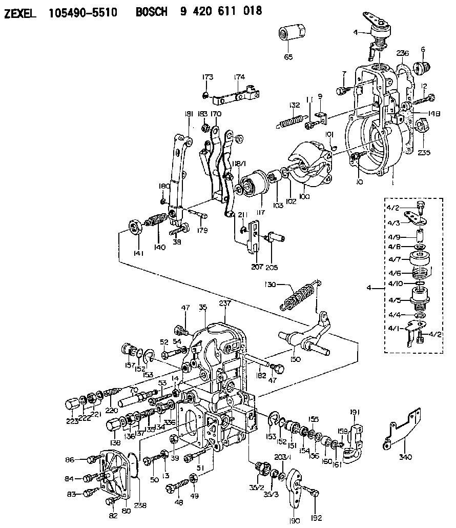
| 1. | [1] | 154004-0800 | GOVERNOR HOUSING |
| 4. | [1] | 154364-2620 | CONTROL LEVER |
| 4. | [1] | 154364-2620 | CONTROL LEVER |
| 4/1. | [1] | 154304-3500 | CONTROL LEVER |
| 4/2. | [2] | 154352-2000 | BLEEDER SCREW |
| 4/2. | [2] | 154352-2000 | BLEEDER SCREW |
| 4/3. | [1] | 154364-2600 | CONTROL LEVER |
| 4/4. | [1] | 029311-0230 | SHIM D18&10.3T0.5 |
| 4/5. | [1] | 154321-1500 | BUSHING |
| 4/6. | [1] | 154327-3500 | COILED SPRING |
| 4/7. | [1] | 154322-0100 | CAP |
| 4/8. | [1] | 029311-0220 | SHIM D18&10.3T0.2 |
| 4/9. | [1] | 154324-2700 | LEVER SHAFT |
| 4/10. | [1] | 029631-0030 | O-RING &9.8W2.3 |
| 6. | [1] | 154007-0200 | ADAPTOR |
| 7. | [1] | 020018-1840 | BLEEDER SCREW M8P1.25L18 |
| 9. | [1] | 154350-1800 | PLATE |
| 10. | [5] | 029010-6810 | BLEEDER SCREW |
| 11. | [1] | 020106-1640 | BLEEDER SCREW M6P1.0L14 |
| 12. | [1] | 154010-8000 | BLEEDER SCREW |
| 13. | [1] | 029240-6010 | UNION NUT M6P1.0H5* |
| 14. | [1] | 154011-0100 | HEXAGON NUT |
| 14B. | [1] | 154011-2300 | UNION NUT |
| 35. | [1] | 154514-4020 | GOVERNOR COVER |
| 35/2. | [1] | 154321-2000 | BUSHING |
| 35/3. | [1] | 029621-0080 | PACKING RING |
| 38. | [1] | 154031-3401 | FLAT-HEAD SCREW |
| 39. | [1] | 029201-0160 | UNION NUT |
| 47. | [2] | 154036-1800 | CAPSULE |
| 47. | [2] | 154036-1800 | CAPSULE |
| 48. | [1] | 154010-5500 | BLEEDER SCREW M10P1.25L42 |
| 49. | [1] | 154011-2100 | UNION NUT |
| 50. | [1] | 155615-1900 | BLEEDER SCREW |
| 51. | [5] | 020106-4540 | BLEEDER SCREW M6P1.0L45 |
| 52. | [2] | 029010-6850 | BLEEDER SCREW |
| 53. | [1] | 154010-2900 | BLEEDER SCREW |
| 54. | [2] | 014110-6440 | LOCKING WASHER |
| 65. | [1] | 155404-5700 | CAP |
| 70. | [1] | 154055-0420 | HEADLESS SCREW |
| 80. | [1] | 154063-3120 | COVER |
| 82. | [1] | 029020-6210 | BLEEDER SCREW |
| 83. | [1] | 020006-1640 | BLEEDER SCREW M6P1L16 4T |
| 84. | [1] | 029020-6210 | BLEEDER SCREW |
| 86. | [1] | 020006-1640 | BLEEDER SCREW M6P1L16 4T |
| 100. | [1] | 154100-9320 | FLYWEIGHT ASSEMBLY |
| 101. | [1] | 025803-1610 | WOODRUFF KEY |
| 102. | [1] | 029321-2020 | LOCKING WASHER |
| 103. | [1] | 139212-0000 | UNION NUT |
| 117. | [1] | 154123-2320 | SLIDING PIECE |
| 118/1. | [0] | 029311-0010 | SHIM D14&10.1T0.2 |
| 118/1. | [0] | 029311-0180 | SHIM D14&10.1T0.3 |
| 118/1. | [0] | 029311-0190 | SHIM D14&10.1T0.40 |
| 118/1. | [0] | 029311-0210 | SHIM D14&10.1T1 |
| 118/1. | [0] | 139410-0000 | SHIM D14.0&10.1T0.5 |
| 118/1. | [0] | 139410-0100 | SHIM D14.0&10.1T1.5 |
| 118/1. | [0] | 139410-3000 | SHIM D14&10.1T2.0 |
| 118/1. | [0] | 139410-3100 | SHIM D14&10.1T3.0 |
| 118/1. | [0] | 139410-3200 | SHIM D14&10.1T4.0 |
| 130. | [1] | 154150-7900 | GOVERNOR SPRING |
| 132. | [1] | 154154-0701 | COILED SPRING |
| 134. | [1] | 154370-3000 | ADAPTOR |
| 135. | [1] | 154158-0920 | HEADLESS SCREW |
| 136. | [1] | 029201-2130 | UNION NUT M12P1.0H6 |
| 137. | [2] | 026512-1540 | GASKET D15.4&12.2T1.50 |
| 138. | [1] | 154159-1200 | CAP NUT |
| 140. | [1] | 154180-3520 | HEADLESS SCREW |
| 141. | [1] | 139218-0100 | UNION NUT |
| 150. | [1] | 154200-5701 | SWIVELLING LEVER |
| 151. | [1] | 154200-5501 | BUSHING |
| 152. | [2] | 139700-0000 | O-RING |
| 152. | [2] | 139700-0000 | O-RING |
| 153. | [2] | 154354-3900 | LOCKING WASHER |
| 153. | [2] | 154354-3900 | LOCKING WASHER |
| 154. | [1] | 139610-0101 | PACKING RING |
| 155. | [1] | 139411-0100 | SHIM D22.0&12.0T0.40 |
| 156. | [0] | 139411-0200 | SHIM D18.0&12.0T0.10 |
| 156B. | [0] | 139411-0300 | SHIM D18.0&12.0T0.20 |
| 156C. | [0] | 139411-0400 | SHIM D18.0&12.0T0.30 |
| 157. | [1] | 154204-3500 | BUSHING |
| 159. | [1] | 025803-1310 | WOODRUFF KEY |
| 160. | [1] | 154206-2300 | BUSHING |
| 161. | [0] | 154206-2400 | PLAIN WASHER D20.5&12.2T1 |
| 170. | [1] | 154216-3020 | FORK LEVER |
| 173. | [1] | 016010-0540 | LOCKING WASHER |
| 174. | [1] | 154230-6820 | STRAP |
| 179. | [1] | 154238-0201 | BEARING PIN |
| 180. | [1] | 016010-0540 | LOCKING WASHER |
| 181. | [1] | 154236-5200 | TENSIONING LEVER |
| 182. | [1] | 154237-1200 | BEARING PIN |
| 183. | [2] | 154237-1300 | BUSHING |
| 190. | [1] | 154360-2800 | CONTROL LEVER |
| 191. | [1] | 154340-1920 | CONTROL LEVER |
| 192. | [1] | 020006-1670 | BLEEDER SCREW M6P1L16 7T |
| 203/1. | [0] | 029311-0640 | SHIM D26.0&10.2T0.95 |
| 203/1. | [0] | 029311-0650 | SHIM D26.0&10.2T0.20 |
| 203/1. | [0] | 029311-0660 | SHIM D26.0&10.2T0.25 |
| 203/1. | [0] | 029311-0670 | SHIM D26.0&10.2T0.30 |
| 203/1. | [0] | 029311-0680 | SHIM D26.0&10.2T0.35 |
| 203/1. | [0] | 029311-0690 | SHIM D26.0&10.2T0.40 |
| 203/1. | [0] | 029311-0700 | SHIM D26.0&10.2T0.50 |
| 203/1. | [0] | 139410-1400 | SHIM D26&10.2T0.7 |
| 203/1. | [0] | 139410-1500 | SHIM D26&10.2T0.9 |
| 203/1. | [0] | 139410-1600 | SHIM D26&10.2T0.8 |
| 203/1. | [0] | 139410-2700 | SHIM D26&10.2T0.6 |
| 205. | [1] | 154324-4100 | LEVER SHAFT |
| 207. | [1] | 154326-0300 | CONTROL LEVER |
| 211. | [1] | 016010-0840 | LOCKING WASHER |
| 220. | [1] | 154050-6820 | HEADLESS SCREW |
| 221. | [1] | 029201-2130 | UNION NUT M12P1.0H6 |
| 222. | [2] | 026512-1540 | GASKET D15.4&12.2T1.50 |
| 223. | [1] | 154159-1200 | CAP NUT |
| 235. | [1] | 155412-5300 | IMPELLER WHEEL |
| 236. | [1] | 154390-0000 | GASKET |
| 237. | [1] | 154390-0200 | GASKET |
| 238. | [1] | 139700-0100 | O-RING |
| 336. | [1] | 029331-6030 | GASKET |
| 340. | [1] | 154213-5800 | BRACKET |
Cross reference number
Zexel num
Bosch num
Firm num
Name
105490-5510
ME726394 MITSUBISHI
GOVERNOR
K 14JN MECHANICAL GOVERNOR GOV RFD GOV
K 14JN MECHANICAL GOVERNOR GOV RFD GOV
Information:
Installation procedure
Installation: Oil pan* Clean the sealant application surfaces of each part. * Apply a bead of sealant to each of the mating surfaces of the timing gear case, lower crankcase and front plate (at the two locations indicated the illustration). Installation: Oil pan* Clean the mating surfaces of each part. * Apply a bead of sealant to the mating surface of the oil pan evenly and without any breaks.* Mount the oil pan within three minutes of applying the sealant. Make sure that the sealant stays in place.
* Do not start the engine less than an hour after installation. If the oil pan mounting bolts were loosened or removed, be sure to reapply sealant.
Oil Pump
* Disassembly sequence1 Oil pump cover2 Driven gear3 Plug4 Relief valve spring5 Steel ball6 Gear and case7 O-ring*a Drive gear*b Oil pump gearP Locating pinX Non-reusable parts* Assembly sequenceFollow the disassembly procedure in reverse.Service standards (Unit: mm) Tightening torque (Unit: N m {kgf m}) Lubricant and/or sealant Inspection procedure
Inspection: Oil pump cover, driven gear, and gear and case* Measure the clearance between each gear's shaft and the oil pump cover, as well as between each gear's shaft and the gear and case. * If the measurements are not within the standard value range, replace the defective part(s). Inspection: Driven gear, drive gear and gear and case* Carry out the following inspection. Replace the oil pump if any defects are found. (1) Sinkage of each gear from gear and case end surface(2) Gear and case-to-tooth tip clearance for each gear Oil Cooler <Engine-Mounted Type, Engine Separately Mounted Type>, and Oil Filter <Engine-Mounted Type>
* Wipe up any spilled engine oil, as it can cause fires.* To avoid any risks of burns, take care not to touch the engine oil when the engine is hot.
* Make sure not to put any engine oil on the belt when working on the oil cooler and oil filter. Belt soiled with oil or grease may easily slip, resulting in deteriorated performance of the cooling system.* Do not reuse the oil filter elements by washing.
* Removal sequence1 Oil filter2 Plug3 Regulator valve spring4 Regulator valve5 Plug6 Bypass valve spring7 Bypass valve8 Oil cooler element9 Gasket10 Water drain plug11 Oil cooler body12 O-ring13 Gasket14 Water separate lipX Non-reusable parts* Installation sequenceFollow the removal sequence in reverse.Service standards (Unit: mm) Tightening torque (Unit: N m {kgf m}) Lubricant and/or sealant Special tools Removal procedure
Removal: Oil filter <Engine-mounted type> Inspection procedure
Inspection: Oil cooler element* Plug the outlet of the oil cooler element and connect a hose to the engine oil inlet port. Then, immerse the oil cooler element in a tank of water. * Apply an air pressure of 1.5 MPa {15 kgf/cm2} for 15 seconds through the hose, and check for any air leaks.* Replace the element if it leaks air.Installation procedure
Installation: Oil cooler <Engine-mounted type>* Clean the oil filter mounting surface of the oil cooler. * Apply a thin coat of engine oil on the oil filter gasket.* Screw in the