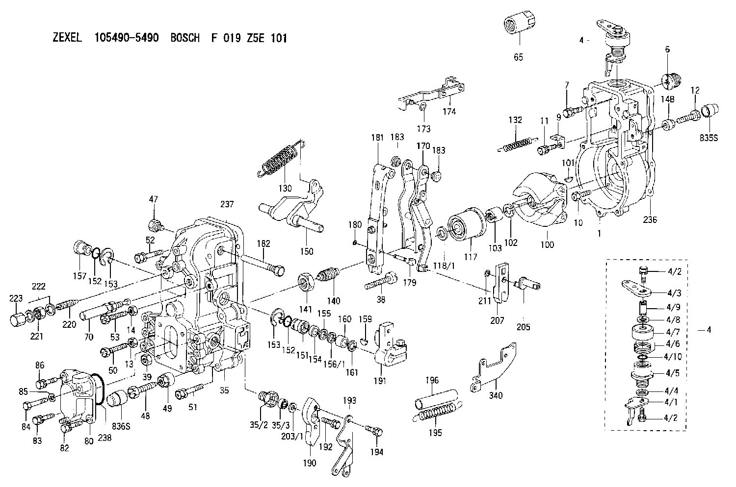
Information governor
BOSCH
F 019 Z5E 101
f019z5e101
ZEXEL
105490-5490
1054905490
MITSUBISHI
ME726275
me726275
Rating:
Scheme ###:
| 1. | [1] | 154000-8300 | GOVERNOR HOUSING |
| 4. | [1] | 154364-2620 | CONTROL LEVER |
| 4. | [1] | 154364-2620 | CONTROL LEVER |
| 4/1. | [1] | 154304-3500 | CONTROL LEVER |
| 4/2. | [2] | 154352-2000 | BLEEDER SCREW |
| 4/2. | [2] | 154352-2000 | BLEEDER SCREW |
| 4/3. | [1] | 154364-2600 | CONTROL LEVER |
| 4/4. | [1] | 029311-0230 | SHIM D18&10.3T0.5 |
| 4/5. | [1] | 154321-1500 | BUSHING |
| 4/6. | [1] | 154327-3500 | COILED SPRING |
| 4/7. | [1] | 154322-0100 | CAP |
| 4/8. | [1] | 029311-0220 | SHIM D18&10.3T0.2 |
| 4/9. | [1] | 154324-2700 | LEVER SHAFT |
| 4/10. | [1] | 029631-0030 | O-RING &9.8W2.3 |
| 6. | [1] | 154007-0200 | ADAPTOR |
| 7. | [1] | 020018-1840 | BLEEDER SCREW M8P1.25L18 |
| 9. | [1] | 154350-1800 | PLATE |
| 10. | [5] | 029010-6810 | BLEEDER SCREW |
| 11. | [1] | 020106-1640 | BLEEDER SCREW M6P1.0L14 |
| 12. | [1] | 154010-7400 | BLEEDER SCREW M8P1.25L55 |
| 12B. | [1] | 154010-7300 | BLEEDER SCREW M8P1.25L60 |
| 13. | [1] | 013020-6040 | UNION NUT M6P1H5 |
| 14. | [1] | 013020-8040 | UNION NUT M8P1.25H7 |
| 14B. | [1] | 154011-2300 | UNION NUT |
| 35. | [1] | 154513-2220 | GOVERNOR COVER |
| 35/2. | [1] | 154321-1800 | BUSHING |
| 35/3. | [1] | 029621-0080 | PACKING RING |
| 38. | [1] | 154031-3500 | FLAT-HEAD SCREW |
| 39. | [1] | 154011-1600 | UNION NUT |
| 47. | [1] | 154036-0300 | CAPSULE |
| 48. | [1] | 154010-7100 | BLEEDER SCREW M10P1.25L47 |
| 48B. | [1] | 154010-8200 | BLEEDER SCREW |
| 49. | [1] | 154011-2200 | UNION NUT |
| 50. | [1] | 155615-1600 | BLEEDER SCREW |
| 51. | [4] | 020106-3840 | BLEEDER SCREW |
| 52. | [2] | 020106-5040 | BLEEDER SCREW |
| 53. | [1] | 154010-7400 | BLEEDER SCREW M8P1.25L55 |
| 65. | [1] | 155404-3800 | CAP |
| 70. | [1] | 154055-0220 | HEADLESS SCREW |
| 80. | [1] | 154060-0020 | COVER |
| 82. | [1] | 029020-6210 | BLEEDER SCREW |
| 83. | [1] | 020006-1640 | BLEEDER SCREW M6P1L16 4T |
| 84. | [1] | 029020-6220 | BLEEDER SCREW |
| 85. | [1] | 014110-6440 | LOCKING WASHER |
| 86. | [1] | 020006-1640 | BLEEDER SCREW M6P1L16 4T |
| 100. | [1] | 154100-9520 | FLYWEIGHT ASSEMBLY |
| 101. | [1] | 025803-1610 | WOODRUFF KEY |
| 102. | [1] | 029321-2020 | LOCKING WASHER |
| 103. | [1] | 029231-2030 | UNION NUT |
| 117. | [1] | 154123-2320 | SLIDING PIECE |
| 118/1. | [0] | 029311-0010 | SHIM D14&10.1T0.2 |
| 118/1. | [0] | 029311-0180 | SHIM D14&10.1T0.3 |
| 118/1. | [0] | 029311-0190 | SHIM D14&10.1T0.40 |
| 118/1. | [0] | 029311-0210 | SHIM D14&10.1T1 |
| 118/1. | [0] | 139410-0000 | SHIM D14.0&10.1T0.5 |
| 118/1. | [0] | 139410-0100 | SHIM D14.0&10.1T1.5 |
| 118/1. | [0] | 139410-3000 | SHIM D14&10.1T2.0 |
| 118/1. | [0] | 139410-3100 | SHIM D14&10.1T3.0 |
| 118/1. | [0] | 139410-3200 | SHIM D14&10.1T4.0 |
| 130. | [1] | 154150-6200 | GOVERNOR SPRING |
| 132. | [1] | 154154-2601 | COILED SPRING |
| 140. | [1] | 154180-4220 | HEADLESS SCREW |
| 141. | [1] | 029201-6010 | UNION NUT |
| 150. | [1] | 154200-3801 | SWIVELLING LEVER |
| 151. | [1] | 154204-2001 | BUSHING |
| 152. | [2] | 029631-8020 | O-RING |
| 152. | [2] | 029631-8020 | O-RING |
| 153. | [2] | 154354-3900 | LOCKING WASHER |
| 153. | [2] | 154354-3900 | LOCKING WASHER |
| 154. | [1] | 139611-0000 | PACKING RING |
| 155. | [1] | 139411-0000 | SHIM |
| 156/1. | [0] | 029311-1110 | SHIM D17&11T0.1 |
| 156/1. | [0] | 029311-1120 | SHIM D17&11T0.2 |
| 156/1. | [0] | 029311-1130 | SHIM D17&11T0.3 |
| 157. | [1] | 154204-3400 | BUSHING |
| 159. | [1] | 025803-1310 | WOODRUFF KEY |
| 160. | [1] | 154206-0900 | BUSHING |
| 161. | [0] | 154206-0200 | PLAIN WASHER D19.5&11.2T1.0 |
| 170. | [1] | 154216-2620 | FORK LEVER |
| 173. | [1] | 016010-0540 | LOCKING WASHER |
| 174. | [1] | 154230-4720 | STRAP |
| 179. | [1] | 154238-0301 | BEARING PIN |
| 180. | [1] | 016010-0540 | LOCKING WASHER |
| 181. | [1] | 154236-5300 | TENSIONING LEVER |
| 182. | [1] | 154237-0900 | BEARING PIN |
| 183. | [2] | 154237-0600 | BUSHING |
| 183. | [2] | 154237-0600 | BUSHING |
| 190. | [1] | 154360-2800 | CONTROL LEVER |
| 191. | [1] | 154340-0820 | CONTROL LEVER |
| 192. | [1] | 020006-1670 | BLEEDER SCREW M6P1L16 7T |
| 193. | [1] | 154361-3400 | CONTROL LEVER |
| 194. | [2] | 020006-1240 | BLEEDER SCREW M6P1L12 4T |
| 195. | [1] | 154314-6900 | COILED SPRING |
| 196. | [1] | 154156-0500 | TUBE |
| 203/1. | [0] | 029311-0640 | SHIM D26.0&10.2T0.95 |
| 203/1. | [0] | 029311-0650 | SHIM D26.0&10.2T0.20 |
| 203/1. | [0] | 029311-0660 | SHIM D26.0&10.2T0.25 |
| 203/1. | [0] | 029311-0670 | SHIM D26.0&10.2T0.30 |
| 203/1. | [0] | 029311-0680 | SHIM D26.0&10.2T0.35 |
| 203/1. | [0] | 029311-0690 | SHIM D26.0&10.2T0.40 |
| 203/1. | [0] | 029311-0700 | SHIM D26.0&10.2T0.50 |
| 203/1. | [0] | 139410-1400 | SHIM D26&10.2T0.7 |
| 203/1. | [0] | 139410-1500 | SHIM D26&10.2T0.9 |
| 203/1. | [0] | 139410-1600 | SHIM D26&10.2T0.8 |
| 203/1. | [0] | 139410-2700 | SHIM D26&10.2T0.6 |
| 205. | [1] | 154324-4500 | LEVER SHAFT |
| 207. | [1] | 154326-0300 | CONTROL LEVER |
| 211. | [1] | 016010-0840 | LOCKING WASHER |
| 220. | [1] | 154050-2320 | HEADLESS SCREW |
| 221. | [1] | 029201-2130 | UNION NUT M12P1.0H6 |
| 222. | [2] | 026512-1540 | GASKET D15.4&12.2T1.50 |
| 223. | [1] | 154159-1200 | CAP NUT |
| 236. | [1] | 154390-0000 | GASKET |
| 237. | [1] | 154390-0300 | GASKET |
| 238. | [1] | 029635-2020 | O-RING |
| 340. | [1] | 154213-5800 | BRACKET |
| 835S. | [2] | 154062-1700 | CAP D20L32 |
Include in #1:
101606-1991
as GOVERNOR
Cross reference number
Zexel num
Bosch num
Firm num
Name
Information:
(b) 4.248 Engines (4 Ring)
**Spring Loaded Conformable Scraper - above gudgeon pin.Internally Stepped Compression - third groove.*Internally Stepped Compression - second groove.Chrome Insert Barrel Faced Compression - top groove.When fitting sealed power rings, ensure that the ends of the spring loaded segment butt together and do not overlap.**Some earlier A4.248 engines had a sealed power scraper ring fitted in the 4th groove. *On some earlier A4.248 engines rated up to 2,000 rev/min, the second compression ring is plain cast iron.Some later engines, rated up to 2,000 rev/min, have internally stepped chrome faced rings in both 2nd and 3rd grooves.When fitting internally stepped compression rings, ensure that the step is towards the piston crown.When fitting the spring loaded conformable scraper ring, ensure that the latch pin enters both ends of the spring. With the ring gap diametrically opposite to the latch pin, position the oil control ring over spring correctly located in annular groove of ring, i.e., between the oil control ring and the bottom of the ring groove in the piston.(c) 4.248 Engines (3 Ring)
Chrome Faced Spring Loaded ConformableScraper - above gudgeon pin.Internally Stepped Taper Faced Compression - second groove.Molybdenum Faced Internally Stepped Barrel Faced Compression - top groove.When fitting the spring loaded conformable scraper ring, ensure that the latch pin enters both ends of the spring. With the ring gap diametrically opposite to the latch pin, position the oil control ring over the spring correctly located in the annular groove of ring, i.e., between the oil control ring and the bottom of the ring groove in the piston.When fitting the internally stepped compression rings in the second and top grooves, ensure that the "step" is towards the piston crown.(d) T4.236 Engines (see Fig. F.6)
F6Chrome Faced Spring Loaded Conformable Scraper - above gudgeon pin.Cast Iron Taper Faced Compression - second groove.Molybdenum Faced Wedge Compression - top groove.When fitting the spring loaded conformable scraper ring, ensure that the latch pin enters both ends of the spring. With the ring gap diametrically opposite to the latch pin, position the oil control ring over spring correctly located in annular groove, i.e., between the oil control ring and the bottom of the ring groove in the piston.When fitting the compression rings, ensure that the manufacturers mark is towards the piston crown.(e) 4.236 Engines fitted with cast iron liners
Slotted Scraper - below gudgeon pin.Slotted Scraper - above gudgeon pin.Internally Stepped Compression - third groove.Internally Stepped Compression - second groove.*Chrome Faced Compression - top groove*With later combine engines, a plain cast iron ring is fitted in the top groove. This plain ring is completely interchangeable with the earlier chrome faced ring. When overhauling combine engines, the later plain ring should always be fitted (in engine sets). From Engine No. 236U68569 fitted to combine applications, some piston ring packs have been altered from five to four rings. The two slotted scraper rings fitted in the forth and fifth grooves have been replaced by one conformable chrome faced ring in the fourth groove only, leaving the