Information governor
BOSCH
9 420 613 556
9420613556
ZEXEL
105490-5461
1054905461
MITSUBISHI
ME727054
me727054

Rating:
Scheme ###:
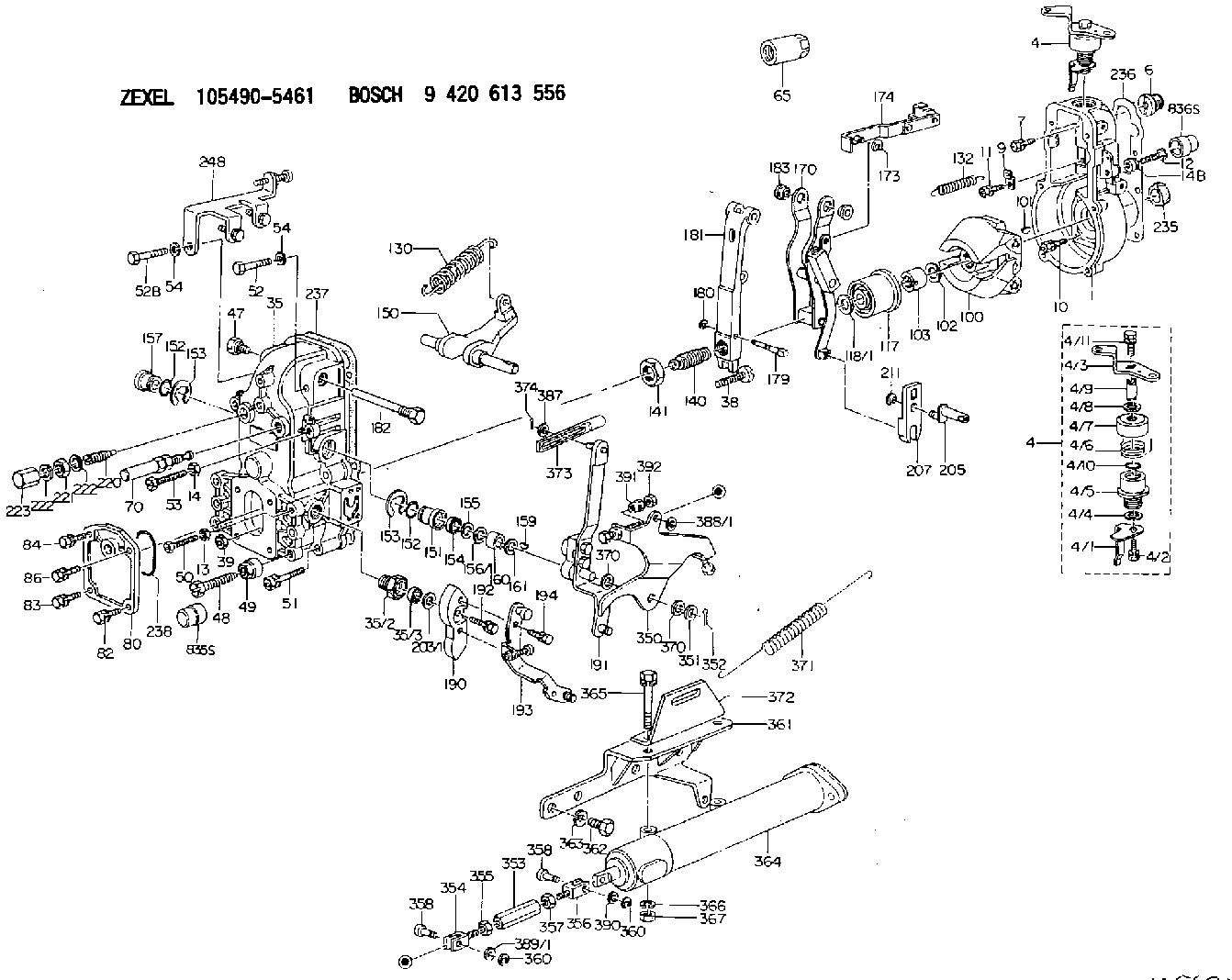
| 1. | [1] | 154004-2900 | GOVERNOR HOUSING |
| 4. | [1] | 154365-4220 | CONTROL LEVER |
| 4. | [1] | 154365-4220 | CONTROL LEVER |
| 4/1. | [1] | 154304-3500 | CONTROL LEVER |
| 4/2. | [1] | 154352-2000 | BLEEDER SCREW |
| 4/3. | [1] | 154365-4200 | CONTROL LEVER |
| 4/4. | [1] | 029311-0230 | SHIM D18&10.3T0.5 |
| 4/5. | [1] | 154321-1500 | BUSHING |
| 4/6. | [1] | 154327-4600 | COILED SPRING |
| 4/7. | [1] | 154322-0100 | CAP |
| 4/8. | [1] | 029311-0220 | SHIM D18&10.3T0.2 |
| 4/9. | [1] | 154324-2700 | LEVER SHAFT |
| 4/10. | [1] | 029631-0030 | O-RING &9.8W2.3 |
| 4/11. | [1] | 020006-1240 | BLEEDER SCREW M6P1L12 4T |
| 6. | [1] | 154007-0200 | ADAPTOR |
| 7. | [1] | 020018-1840 | BLEEDER SCREW M8P1.25L18 |
| 9. | [1] | 154350-1800 | PLATE |
| 10. | [5] | 029010-6810 | BLEEDER SCREW |
| 11. | [1] | 020106-1640 | BLEEDER SCREW M6P1.0L14 |
| 12. | [1] | 154010-7800 | BLEEDER SCREW |
| 13. | [1] | 013020-6040 | UNION NUT M6P1H5 |
| 14. | [1] | 013020-8040 | UNION NUT M8P1.25H7 |
| 14B. | [1] | 154011-2300 | UNION NUT |
| 35. | [1] | 154513-2320 | GOVERNOR COVER |
| 35/2. | [1] | 154321-1800 | BUSHING |
| 35/3. | [1] | 029621-0080 | PACKING RING |
| 38. | [1] | 154031-3500 | FLAT-HEAD SCREW |
| 39. | [1] | 154011-1600 | UNION NUT |
| 47. | [1] | 154036-1200 | CAPSULE |
| 48. | [1] | 154010-7100 | BLEEDER SCREW M10P1.25L47 |
| 48B. | [1] | 154010-7700 | BLEEDER SCREW M10P1.25L51 |
| 49. | [1] | 154011-2200 | UNION NUT |
| 50. | [1] | 155615-1600 | BLEEDER SCREW |
| 51. | [4] | 020106-3840 | BLEEDER SCREW |
| 52. | [1] | 010006-5040 | BLEEDER SCREW M6P1L50 |
| 52B. | [1] | 010006-5540 | BLEEDER SCREW M6P1L55 4T |
| 53. | [1] | 154010-7400 | BLEEDER SCREW M8P1.25L55 |
| 54. | [2] | 014110-6440 | LOCKING WASHER |
| 54. | [2] | 014110-6440 | LOCKING WASHER |
| 65. | [1] | 155404-5700 | CAP |
| 70. | [1] | 154055-0520 | HEADLESS SCREW |
| 80. | [1] | 154060-4900 | COVER |
| 82. | [1] | 020006-1640 | BLEEDER SCREW M6P1L16 4T |
| 83. | [1] | 029020-6210 | BLEEDER SCREW |
| 84. | [1] | 020006-1640 | BLEEDER SCREW M6P1L16 4T |
| 86. | [1] | 029020-6210 | BLEEDER SCREW |
| 100. | [1] | 154100-9520 | FLYWEIGHT ASSEMBLY |
| 101. | [1] | 025803-1610 | WOODRUFF KEY |
| 102. | [1] | 029321-2020 | LOCKING WASHER |
| 103. | [1] | 029231-2030 | UNION NUT |
| 117. | [1] | 154123-2320 | SLIDING PIECE |
| 118/1. | [0] | 029311-0010 | SHIM D14&10.1T0.2 |
| 118/1. | [0] | 029311-0180 | SHIM D14&10.1T0.3 |
| 118/1. | [0] | 029311-0190 | SHIM D14&10.1T0.40 |
| 118/1. | [0] | 029311-0210 | SHIM D14&10.1T1 |
| 118/1. | [0] | 139410-0000 | SHIM D14.0&10.1T0.5 |
| 118/1. | [0] | 139410-0100 | SHIM D14.0&10.1T1.5 |
| 118/1. | [0] | 139410-3000 | SHIM D14&10.1T2.0 |
| 118/1. | [0] | 139410-3100 | SHIM D14&10.1T3.0 |
| 118/1. | [0] | 139410-3200 | SHIM D14&10.1T4.0 |
| 130. | [1] | 154150-7000 | GOVERNOR SPRING |
| 132. | [1] | 154154-0800 | COILED SPRING |
| 140. | [1] | 154180-0720 | HEADLESS SCREW |
| 141. | [1] | 029201-6010 | UNION NUT |
| 150. | [1] | 154200-3801 | SWIVELLING LEVER |
| 151. | [1] | 154204-2001 | BUSHING |
| 152. | [2] | 029631-8020 | O-RING |
| 152. | [2] | 029631-8020 | O-RING |
| 153. | [2] | 154354-3900 | LOCKING WASHER |
| 153. | [2] | 154354-3900 | LOCKING WASHER |
| 154. | [1] | 139611-0000 | PACKING RING |
| 155. | [1] | 139411-0000 | SHIM |
| 156/1. | [0] | 029311-1110 | SHIM D17&11T0.1 |
| 156/1. | [0] | 029311-1120 | SHIM D17&11T0.2 |
| 156/1. | [0] | 029311-1130 | SHIM D17&11T0.3 |
| 157. | [1] | 154204-3400 | BUSHING |
| 159. | [1] | 025803-1310 | WOODRUFF KEY |
| 160. | [1] | 154206-0900 | BUSHING |
| 161. | [0] | 154206-0200 | PLAIN WASHER D19.5&11.2T1.0 |
| 170. | [1] | 154216-2620 | FORK LEVER |
| 173. | [1] | 016010-0540 | LOCKING WASHER |
| 174. | [1] | 154230-4720 | STRAP |
| 179. | [1] | 154238-0301 | BEARING PIN |
| 180. | [1] | 016010-0540 | LOCKING WASHER |
| 181. | [1] | 154236-5300 | TENSIONING LEVER |
| 182. | [1] | 154237-0900 | BEARING PIN |
| 183. | [2] | 154237-0600 | BUSHING |
| 190. | [1] | 154360-2800 | CONTROL LEVER |
| 191. | [1] | 154342-7420 | CONTROL LEVER |
| 192. | [1] | 020006-1670 | BLEEDER SCREW M6P1L16 7T |
| 193. | [1] | 154368-5420 | CONTROL LEVER |
| 194. | [2] | 020006-1240 | BLEEDER SCREW M6P1L12 4T |
| 203/1. | [0] | 029311-0640 | SHIM D26.0&10.2T0.95 |
| 203/1. | [0] | 029311-0650 | SHIM D26.0&10.2T0.20 |
| 203/1. | [0] | 029311-0660 | SHIM D26.0&10.2T0.25 |
| 203/1. | [0] | 029311-0670 | SHIM D26.0&10.2T0.30 |
| 203/1. | [0] | 029311-0680 | SHIM D26.0&10.2T0.35 |
| 203/1. | [0] | 029311-0690 | SHIM D26.0&10.2T0.40 |
| 203/1. | [0] | 029311-0700 | SHIM D26.0&10.2T0.50 |
| 203/1. | [0] | 139410-1400 | SHIM D26&10.2T0.7 |
| 203/1. | [0] | 139410-1500 | SHIM D26&10.2T0.9 |
| 203/1. | [0] | 139410-1600 | SHIM D26&10.2T0.8 |
| 203/1. | [0] | 139410-2700 | SHIM D26&10.2T0.6 |
| 205. | [1] | 154324-4500 | LEVER SHAFT |
| 207. | [1] | 154326-0300 | CONTROL LEVER |
| 211. | [1] | 016010-0840 | LOCKING WASHER |
| 220. | [1] | 154050-3520 | HEADLESS SCREW |
| 221. | [1] | 029201-2130 | UNION NUT M12P1.0H6 |
| 222. | [2] | 026512-1540 | GASKET D15.4&12.2T1.50 |
| 222. | [2] | 026512-1540 | GASKET D15.4&12.2T1.50 |
| 223. | [1] | 154159-1200 | CAP NUT |
| 235. | [1] | 155412-5200 | IMPELLER WHEEL |
| 236. | [1] | 154390-1300 | GASKET |
| 237. | [1] | 154390-0300 | GASKET |
| 238. | [1] | 029635-2020 | O-RING |
| 248. | [1] | 154358-1620 | BRACKET |
| 350. | [1] | 154372-6020 | CONTROL LEVER |
| 351. | [1] | 014010-8140 | PLAIN WASHER D18&8.5T1.6 |
| 352. | [1] | 015316-1290 | SPLIT PIN |
| 353. | [1] | 154353-3300 | UNION NUT M6P1H50 |
| 353B. | [1] | 154351-9200 | UNION NUT M6P1H40 |
| 354. | [1] | 154351-9300 | CLEVIS |
| 355. | [1] | 013020-6040 | UNION NUT M6P1H5 |
| 356. | [1] | 154351-9400 | CLEVIS |
| 357. | [1] | 029200-6210 | UNION NUT |
| 358. | [2] | 154604-2400 | BEARING PIN |
| 358. | [2] | 154604-2400 | BEARING PIN |
| 360. | [2] | 016010-0640 | LOCKING WASHER |
| 360. | [2] | 016010-0640 | LOCKING WASHER |
| 361. | [1] | 154371-2020 | BRACKET |
| 362. | [4] | 010038-1440 | BLEEDER SCREW M8P1.25L14 |
| 363. | [4] | 014110-8440 | LOCKING WASHER |
| 364. | [1] | 154352-8920 | AIR CYLINDER |
| 365. | [2] | 010010-6540 | BLEEDER SCREW |
| 366. | [2] | 014111-0440 | LOCKING WASHER |
| 367. | [2] | 013021-0040 | UNION NUT M10P1.5H8 |
| 370. | [0] | 029310-8650 | SHIM D10.5&8.5T0.5 |
| 370. | [0] | 029310-8650 | SHIM D10.5&8.5T0.5 |
| 371. | [1] | 154317-5100 | COILED SPRING |
| 372. | [1] | 154371-2300 | BRACKET |
| 373. | [1] | 154352-4700 | STRAP |
| 374. | [1] | 015316-1290 | SPLIT PIN |
| 387. | [1] | 029310-7030 | SHIM D14.5&7T0.5 |
| 388/1. | [0] | 029300-6010 | PLAIN WASHER D11&6.4T0.8 |
| 388/1. | [0] | 029300-6020 | PLAIN WASHER D11&6.4T0.35 |
| 388/1. | [0] | 029300-6030 | PLAIN WASHER D11&6.4T0.5 |
| 388/1. | [0] | 029300-6040 | PLAIN WASHER D11&6.4T1 |
| 389/1. | [0] | 029300-6010 | PLAIN WASHER D11&6.4T0.8 |
| 389/1. | [0] | 029300-6020 | PLAIN WASHER D11&6.4T0.35 |
| 389/1. | [0] | 029300-6030 | PLAIN WASHER D11&6.4T0.5 |
| 389/1. | [0] | 029300-6040 | PLAIN WASHER D11&6.4T1 |
| 390. | [1] | 029300-8010 | PLAIN WASHER D15&8T1.00 |
| 391. | [0] | 154011-1400 | UNION NUT M6P1H15 |
| 392. | [0] | 013020-6040 | UNION NUT M6P1H5 |
| 835S. | [1] | 154062-1700 | CAP D20L32 |
| 836S. | [1] | 154062-1800 | CAP D20L27 |
Cross reference number
Zexel num
Bosch num
Firm num
Name
105490-5461
ME727054 MITSUBISHI
GOVERNOR
K 14JN MECHANICAL GOVERNOR GOV RFD GOV
K 14JN MECHANICAL GOVERNOR GOV RFD GOV
Information:
Daily or every 8 Hours (whichever occurs first)
Check coolant level.Check oil level in sump (make sure machine is standing level).Check oil pressure (where a gauge is fitted).In extreme dust conditions, clean oil bath air cleaner or empty dust bowl on dry type air cleaner.Every 200 Hours or 4 Months (whichever occurs first)
Clean oil bath air cleaner or empty dust bowl on dry type cleaner.Check drive belt tension.Clean fuel water trap (where fitted).Every 400 Hours or 12 Months (whichever occurs first)
Drain and renew engine lubricating oil.Renew lubricating oil filter canister.Renew final fuel filter element.Clean lift pump sediment chamber.Every 800 Hours
Renew dry type air filter element.Every 2,400 Hours
Arrange for examination and service of proprietary equipment, i.e. starter motor, alternator, etc.Service atomisers.Check and adjust valve clearance.Post-Delivery Checkover
After a customer has taken delivery of his Perkins Diesel engine, a general checkover of the engine must be carried out by an experienced fitter after the first 500/1,000 miles (800/1600 km) or 25/50 hours in service with the engine warm.The checkover should comprise the following points:-1. Drain lubricating oil sump and refill to full mark on dipstick with new oil. See list of Approved Lubricating Oils in Appendix. When the sump is drained and it is possible to gain access to the sump strainer, it is recommended that this be cleaned.2. Renew the lubricating oil filter element.3. Remove the rocker assembly; tighten the cylinder head nuts/setscrews in the correct sequence (see Fig. E.12) and to the correct torque (see Page B.2). (Not necessary for 4.2482 The correct procedure for retightening of cylinder head nuts/setscrews is given on Page E.7. Reset valve tip clearances.4. Check coolant level and check for leaks.5. Check external nuts, setscrews, hose clips, mountings etc. for tightness.6. Check fan belt tension.7. Check electrical equipment and connections.8. Check for lubricating oil leaks.9. Check slow running speed (see Page N.9).10. Check general performance of engine. Routine maintenance should follow as detailed under Preventive Maintenance.Protection of an engine not in service
The recommendations given below are to ensure that damage is prevented when an engine is removed from service for an extended period. Use these procedures immediately the engine is removed from service. The instructions for the use of POWERPART products are given on the outside of each container.1. Thoroughly clean the outside of the engine.2. Where a preservative fuel is to be used, drain the fuel system and fill with the preservative fuel. POWERPART Lay-Up 1 can be added to the normal fuel to change it to a preservative fuel. If preservative fuel is not used, the system can be kept charged with normal fuel but this will have to be drained and discarded at the end of the storage period together with the fuel filter.3. Run the engine until it is warm. Correct any fuel, lubricating oil or air leakage. Stop the engine and drain the lubricating oil sump.4. Renew the lubricating oil filter canister.5. Fill the sump to the full mark on the dipstick with clean new lubricating oil or with