Information governor
BOSCH
9 420 613 554
9420613554
ZEXEL
105490-5410
1054905410
MITSUBISHI
ME723009
me723009
Rating:
Scheme ###:
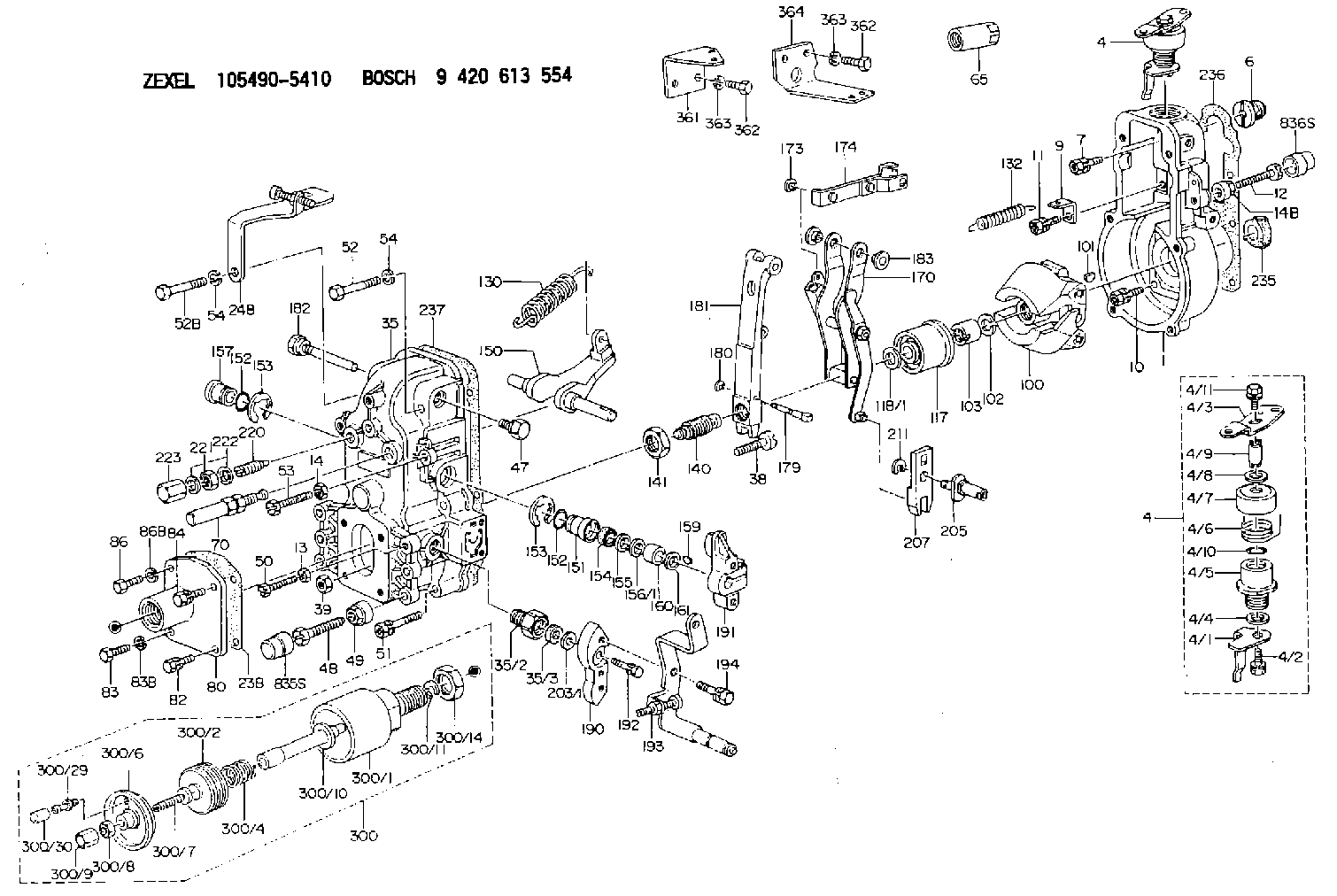
| 1. | [1] | 154000-6800 | GOVERNOR HOUSING |
| 4. | [1] | 154366-2820 | CONTROL LEVER |
| 4. | [1] | 154366-2820 | CONTROL LEVER |
| 4/1. | [1] | 154304-3500 | CONTROL LEVER |
| 4/2. | [1] | 154352-2000 | BLEEDER SCREW |
| 4/3. | [1] | 154366-2800 | CONTROL LEVER |
| 4/4. | [1] | 029311-0230 | SHIM D18&10.3T0.5 |
| 4/5. | [1] | 154321-1500 | BUSHING |
| 4/6. | [1] | 154327-4600 | COILED SPRING |
| 4/7. | [1] | 154322-0100 | CAP |
| 4/8. | [1] | 029311-0220 | SHIM D18&10.3T0.2 |
| 4/9. | [1] | 154324-2700 | LEVER SHAFT |
| 4/10. | [1] | 029631-0030 | O-RING &9.8W2.3 |
| 4/11. | [1] | 020006-1240 | BLEEDER SCREW M6P1L12 4T |
| 6. | [1] | 154007-0200 | ADAPTOR |
| 7. | [1] | 020018-1840 | BLEEDER SCREW M8P1.25L18 |
| 9. | [1] | 154350-1800 | PLATE |
| 10. | [5] | 029010-6810 | BLEEDER SCREW |
| 11. | [1] | 020106-1640 | BLEEDER SCREW M6P1.0L14 |
| 12. | [1] | 154010-7800 | BLEEDER SCREW |
| 13. | [1] | 013020-6040 | UNION NUT M6P1H5 |
| 14. | [1] | 013020-8040 | UNION NUT M8P1.25H7 |
| 14B. | [1] | 154011-2300 | UNION NUT |
| 35. | [1] | 154514-4320 | GOVERNOR COVER |
| 35/2. | [1] | 154321-1800 | BUSHING |
| 35/3. | [1] | 029621-0080 | PACKING RING |
| 38. | [1] | 154031-3500 | FLAT-HEAD SCREW |
| 39. | [1] | 154011-1600 | UNION NUT |
| 47. | [1] | 154036-0300 | CAPSULE |
| 48. | [1] | 154010-7100 | BLEEDER SCREW M10P1.25L47 |
| 48B. | [1] | 154010-7700 | BLEEDER SCREW M10P1.25L51 |
| 49. | [1] | 154011-2200 | UNION NUT |
| 50. | [1] | 155615-1600 | BLEEDER SCREW |
| 51. | [4] | 020106-3840 | BLEEDER SCREW |
| 52. | [1] | 010006-5040 | BLEEDER SCREW M6P1L50 |
| 52B. | [1] | 010006-5540 | BLEEDER SCREW M6P1L55 4T |
| 53. | [1] | 154010-7400 | BLEEDER SCREW M8P1.25L55 |
| 54. | [2] | 014110-6440 | LOCKING WASHER |
| 54. | [2] | 014110-6440 | LOCKING WASHER |
| 65. | [1] | 155404-5700 | CAP |
| 70. | [1] | 154055-0520 | HEADLESS SCREW |
| 80. | [1] | 155423-9521 | SPACER BUSHING |
| 82. | [1] | 020006-2240 | BLEEDER SCREW M6P1L22 |
| 83. | [1] | 020506-2240 | BLEEDER SCREW |
| 83B. | [1] | 014110-6440 | LOCKING WASHER |
| 84. | [1] | 020006-2240 | BLEEDER SCREW M6P1L22 |
| 86. | [1] | 020506-2240 | BLEEDER SCREW |
| 86B. | [1] | 014110-6440 | LOCKING WASHER |
| 100. | [1] | 154100-9520 | FLYWEIGHT ASSEMBLY |
| 101. | [1] | 025803-1610 | WOODRUFF KEY |
| 102. | [1] | 029321-2020 | LOCKING WASHER |
| 103. | [1] | 029231-2030 | UNION NUT |
| 117. | [1] | 154123-2320 | SLIDING PIECE |
| 118/1. | [0] | 029311-0010 | SHIM D14&10.1T0.2 |
| 118/1. | [0] | 029311-0180 | SHIM D14&10.1T0.3 |
| 118/1. | [0] | 029311-0190 | SHIM D14&10.1T0.40 |
| 118/1. | [0] | 029311-0210 | SHIM D14&10.1T1 |
| 118/1. | [0] | 139410-0000 | SHIM D14.0&10.1T0.5 |
| 118/1. | [0] | 139410-0100 | SHIM D14.0&10.1T1.5 |
| 118/1. | [0] | 139410-3000 | SHIM D14&10.1T2.0 |
| 118/1. | [0] | 139410-3100 | SHIM D14&10.1T3.0 |
| 118/1. | [0] | 139410-3200 | SHIM D14&10.1T4.0 |
| 130. | [1] | 154150-7000 | GOVERNOR SPRING |
| 132. | [1] | 154154-0800 | COILED SPRING |
| 140. | [1] | 154180-0720 | HEADLESS SCREW |
| 141. | [1] | 029201-6010 | UNION NUT |
| 150. | [1] | 154200-3801 | SWIVELLING LEVER |
| 151. | [1] | 154204-2001 | BUSHING |
| 152. | [2] | 029631-8020 | O-RING |
| 152. | [2] | 029631-8020 | O-RING |
| 153. | [2] | 154354-3900 | LOCKING WASHER |
| 153. | [2] | 154354-3900 | LOCKING WASHER |
| 154. | [1] | 139611-0000 | PACKING RING |
| 155. | [1] | 139411-0000 | SHIM |
| 156/1. | [0] | 029311-1110 | SHIM D17&11T0.1 |
| 156/1. | [0] | 029311-1120 | SHIM D17&11T0.2 |
| 156/1. | [0] | 029311-1130 | SHIM D17&11T0.3 |
| 157. | [1] | 154204-3400 | BUSHING |
| 159. | [1] | 025803-1310 | WOODRUFF KEY |
| 160. | [1] | 154206-0900 | BUSHING |
| 161. | [0] | 154206-0200 | PLAIN WASHER D19.5&11.2T1.0 |
| 170. | [1] | 154217-1920 | FORK LEVER |
| 173. | [1] | 016010-0540 | LOCKING WASHER |
| 174. | [1] | 154230-4720 | STRAP |
| 179. | [1] | 154238-0301 | BEARING PIN |
| 180. | [1] | 016010-0540 | LOCKING WASHER |
| 181. | [1] | 154236-5300 | TENSIONING LEVER |
| 182. | [1] | 154237-0900 | BEARING PIN |
| 183. | [2] | 154237-0600 | BUSHING |
| 190. | [1] | 154360-2800 | CONTROL LEVER |
| 191. | [1] | 154340-0120 | CONTROL LEVER |
| 192. | [1] | 020006-1670 | BLEEDER SCREW M6P1L16 7T |
| 193. | [1] | 154368-7120 | CONTROL LEVER |
| 194. | [2] | 020006-1240 | BLEEDER SCREW M6P1L12 4T |
| 203/1. | [0] | 029311-0640 | SHIM D26.0&10.2T0.95 |
| 203/1. | [0] | 029311-0650 | SHIM D26.0&10.2T0.20 |
| 203/1. | [0] | 029311-0660 | SHIM D26.0&10.2T0.25 |
| 203/1. | [0] | 029311-0670 | SHIM D26.0&10.2T0.30 |
| 203/1. | [0] | 029311-0680 | SHIM D26.0&10.2T0.35 |
| 203/1. | [0] | 029311-0690 | SHIM D26.0&10.2T0.40 |
| 203/1. | [0] | 029311-0700 | SHIM D26.0&10.2T0.50 |
| 203/1. | [0] | 139410-1400 | SHIM D26&10.2T0.7 |
| 203/1. | [0] | 139410-1500 | SHIM D26&10.2T0.9 |
| 203/1. | [0] | 139410-1600 | SHIM D26&10.2T0.8 |
| 203/1. | [0] | 139410-2700 | SHIM D26&10.2T0.6 |
| 205. | [1] | 154324-4500 | LEVER SHAFT |
| 207. | [1] | 154326-0300 | CONTROL LEVER |
| 211. | [1] | 016010-0840 | LOCKING WASHER |
| 220. | [1] | 154050-1220 | HEADLESS SCREW |
| 221. | [1] | 029201-2140 | UNION NUT |
| 222. | [2] | 026512-1540 | GASKET D15.4&12.2T1.50 |
| 223. | [1] | 154159-1200 | CAP NUT |
| 235. | [1] | 155412-5200 | IMPELLER WHEEL |
| 236. | [1] | 154390-1300 | GASKET |
| 237. | [1] | 154390-0300 | GASKET |
| 238. | [1] | 154390-5100 | GASKET |
| 248. | [1] | 154357-5220 | BRACKET |
| 300. | [1] | 155423-9420 | ANEROID CAPSULE |
| 300/1. | [1] | 155423-3720 | DIAPHRAGM HOUSING |
| 300/2. | [1] | 155403-3021 | BELLOWS |
| 300/4. | [1] | 155423-4000 | COILED SPRING |
| 300/6. | [1] | 155423-2000 | COVER |
| 300/7. | [1] | 155423-1500 | SCREW PLUG |
| 300/8. | [1] | 029240-6010 | UNION NUT M6P1.0H5* |
| 300/9. | [1] | 154035-1600 | CAP NUT |
| 300/10. | [1] | 029311-2060 | SHIM D22&12.5T0.5 |
| 300/11. | [1] | 016020-1220 | LOCKING WASHER |
| 300/14. | [1] | 139222-0000 | UNION NUT |
| 300/29. | [1] | 139805-0000 | JOINT CONNECTION |
| 300/30. | [1] | 155424-0300 | CAP |
| 361. | [1] | 154370-2700 | BRACKET |
| 362. | [4] | 010038-1240 | BLEEDER SCREW |
| 362. | [4] | 010038-1240 | BLEEDER SCREW |
| 363. | [4] | 014110-8440 | LOCKING WASHER |
| 363. | [4] | 014110-8440 | LOCKING WASHER |
| 364. | [1] | 154370-2800 | BRACKET |
| 835S. | [1] | 154062-1700 | CAP D20L32 |
| 836S. | [1] | 154062-1800 | CAP D20L27 |
Cross reference number
Zexel num
Bosch num
Firm num
Name
105490-5410
ME723009 MITSUBISHI
GOVERNOR
K 14JN MECHANICAL GOVERNOR GOV RFD GOV
K 14JN MECHANICAL GOVERNOR GOV RFD GOV
Information:
Checking The Piston
1. If the cylinder is renewed, a new piston must be fitted. Normal and oversizes are given in the specifications.2. Inspect the piston for damage or visible wear, including the bosses.
3-613. Remove the compression rings and bevelled scraper ring. (Use piston-ring expander No. 130300)Fig. 3-61
3-624. Open and remove the expander spring for the bevelled scraper ring.Fig. 3-625. Clean the piston-ring grooves.
3-636. Measure axial piston ring clearance by using commercial tools.Fig. 3-63, leftMeasure first piston ring groove, if trapezoidal, by means of trapezoidal groove wear gauge No. 130360.Fig. 3-63, right
3-64 If, when measuring a piston with trapezoidal ring groove, a gap "S" (Fig. 3-64) is found to exist between the inserted gauge and the piston, this means that the axial piston ring clearance is within the tolerances stated in the Specification Data and the piston is fit for further use.
3-65But if the gauge contacts the side of the piston (see Fig. 3-65), i.e. without gap, the piston has to be renewed.
3-667. Insert all the piston rings singly in the cylinder and press down with the piston to a distance of 30 mm from the cylinder head contacting surface. Measure the gap clearance of the piston ring.Fig. 3-668. Compare the gap clearances of the piston rings with the values given in the specifications.9. Renew defective pistons together with gudgeon pin and rings. Renew also cylinders.
3-6710. When installing the piston rings start by fitting the expander spring for the bevelled scraper ring in the bottom groove.Fig. 3-67
3-6811. Assemble the piston rings with the aid of piston-ring expander No. 130300, in the following sequence:No. 3 (No. 4) Slotted, double-chamfered oil-control ring, chromium-plated.(No. 3) Tapered compression ring, ferrox finished; install with face marked "top" upwards.No. 2 Tapered compression ring, ferrox finished; install with face marked "top" upwards.No. 1 Top, double-trapezoidal compression ring, chromium-plated. "top" upwards.Fig. 3-68 Place the rings so that the gaps are evenly spaced around the piston.
3-6912. Check piston pin for wear using a bevelled steel straight edge or measuring angle, Fig. 3-69.
3-70 Secure the opposite end of the gudgeon pin in position. Place the piston on the small end of the connecting rod so that the exhaust air side of the piston (marked on the piston crown) is in the same direction as the open side of the connecting-rod bearing. Press in the gudgeon pin.Fig. 3-70Checking The Connecting Rod
Gauging and replacing piston pin bush
3-711. Set inside micrometer to starting dimension using a micrometer frame (see Technical Data).Fig. 3-71
3-722. Measure the piston pin bush at points one and two in the planes "a" and "b".Fig. 3-72 Attention:Compare recorded values with those specified in the Technical Data.
3-733. Pull out old piston pin bush with fixture No. 131310 and pull in new piston pin bush with the same device.Fig. 3-73
3-74 Note for installation:Pull in the new piston pin bush flush, making sure that the oil bores in bush and connecting rod coincide.Fig. 3-74Gauging And Replacing Big-End Bearings
3-75The big-end bearings are of finished type. They are made of two half