Information governor
BOSCH
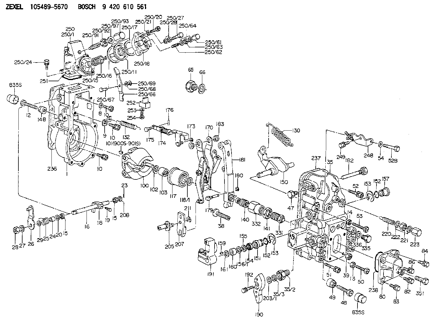
9 420 610 561
9420610561
ZEXEL
105489-5670
1054895670
NISSAN-DIESEL
1910196815
1910196815
Rating:
Scheme ###:
| 1. | [1] | 154004-2822 | GOVERNOR HOUSING |
| 8. | [1] | 139506-0100 | GASKET D12.0&6.2T1.0 |
| 9. | [1] | 154350-6000 | PLATE |
| 10. | [8] | 020106-2040 | BLEEDER SCREW M6P1L20 |
| 10. | [8] | 020106-2040 | BLEEDER SCREW M6P1L20 |
| 10. | [8] | 020106-2040 | BLEEDER SCREW M6P1L20 |
| 12. | [1] | 154010-7200 | BLEEDER SCREW M8P1.25L62 |
| 13. | [1] | 013020-6040 | UNION NUT M6P1H5 |
| 14. | [1] | 154011-0100 | HEXAGON NUT |
| 14B. | [1] | 154011-2300 | UNION NUT |
| 15. | [2] | 029620-8050 | PACKING RING |
| 15. | [2] | 029620-8050 | PACKING RING |
| 16. | [1] | 155004-3600 | LEVER SHAFT |
| 18. | [1] | 155003-2101 | CONTROL LEVER |
| 19. | [1] | 155006-0700 | BLEEDER SCREW |
| 20. | [1] | 139308-0900 | PLAIN WASHER D16&8T1 |
| 20B. | [1] | 139308-1000 | PLAIN WASHER D16&8T1.5 |
| 23. | [1] | 025520-1210 | SPLIT PIN |
| 24. | [1] | 154206-2000 | BUSHING |
| 25. | [1] | 154327-3600 | COILED SPRING |
| 26. | [1] | 154367-9920 | CONTROL LEVER |
| 27. | [1] | 014110-8440 | LOCKING WASHER |
| 28. | [1] | 013020-8040 | UNION NUT M8P1.25H7 |
| 29. | [1] | 139408-1400 | SHIM |
| 29B. | [0] | 139408-1400 | SHIM |
| 29C. | [0] | 139408-1500 | SHIM |
| 35. | [1] | 154515-9720 | GOVERNOR COVER |
| 35/2. | [1] | 154321-2300 | BUSHING |
| 35/3. | [1] | 139610-1100 | PACKING RING |
| 38. | [1] | 154031-3500 | FLAT-HEAD SCREW |
| 39. | [1] | 154011-1600 | UNION NUT |
| 47. | [1] | 154036-1200 | CAPSULE |
| 48. | [1] | 154010-7700 | BLEEDER SCREW M10P1.25L51 |
| 48B. | [1] | 154010-7100 | BLEEDER SCREW M10P1.25L47 |
| 49. | [1] | 154011-2200 | UNION NUT |
| 50. | [1] | 155615-1900 | BLEEDER SCREW |
| 51. | [4] | 020106-3840 | BLEEDER SCREW |
| 52. | [1] | 020106-5040 | BLEEDER SCREW |
| 52B. | [1] | 029010-6850 | BLEEDER SCREW |
| 53. | [1] | 154010-3100 | BLEEDER SCREW |
| 54. | [1] | 014110-6440 | LOCKING WASHER |
| 65. | [1] | 155404-1700 | CAP |
| 66. | [1] | 026524-3040 | GASKET |
| 80. | [1] | 154063-4320 | COVER |
| 82. | [1] | 020006-1640 | BLEEDER SCREW M6P1L16 4T |
| 83. | [1] | 029020-6210 | BLEEDER SCREW |
| 84. | [1] | 020006-1640 | BLEEDER SCREW M6P1L16 4T |
| 86. | [1] | 029020-6210 | BLEEDER SCREW |
| 100. | [1] | 154100-9520 | FLYWEIGHT ASSEMBLY |
| 101. | [1] | 025803-1310 | WOODRUFF KEY |
| 102. | [1] | 029321-2020 | LOCKING WASHER |
| 103. | [1] | 029231-2030 | UNION NUT |
| 117. | [1] | 154123-2320 | SLIDING PIECE |
| 118/1. | [0] | 029311-0010 | SHIM D14&10.1T0.2 |
| 118/1. | [0] | 029311-0180 | SHIM D14&10.1T0.3 |
| 118/1. | [0] | 029311-0190 | SHIM D14&10.1T0.40 |
| 118/1. | [0] | 029311-0210 | SHIM D14&10.1T1 |
| 118/1. | [0] | 139410-0000 | SHIM D14.0&10.1T0.5 |
| 118/1. | [0] | 139410-0100 | SHIM D14.0&10.1T1.5 |
| 118/1. | [0] | 139410-3000 | SHIM D14&10.1T2.0 |
| 118/1. | [0] | 139410-3100 | SHIM D14&10.1T3.0 |
| 118/1. | [0] | 139410-3200 | SHIM D14&10.1T4.0 |
| 130. | [1] | 154150-7200 | GOVERNOR SPRING |
| 132. | [1] | 154154-0200 | COILED SPRING |
| 140. | [1] | 154180-7020 | HEADLESS SCREW |
| 141. | [1] | 029201-6010 | UNION NUT |
| 150. | [1] | 154200-3701 | SWIVELLING LEVER |
| 151. | [1] | 154204-2001 | BUSHING |
| 152. | [2] | 029631-8020 | O-RING |
| 152. | [2] | 029631-8020 | O-RING |
| 153. | [2] | 154354-3900 | LOCKING WASHER |
| 153. | [2] | 154354-3900 | LOCKING WASHER |
| 154. | [1] | 139611-0000 | PACKING RING |
| 155. | [1] | 139411-0000 | SHIM |
| 156/1. | [0] | 029311-1110 | SHIM D17&11T0.1 |
| 156/1. | [0] | 029311-1120 | SHIM D17&11T0.2 |
| 156/1. | [0] | 029311-1130 | SHIM D17&11T0.3 |
| 157. | [1] | 154204-3400 | BUSHING |
| 159. | [1] | 025803-1310 | WOODRUFF KEY |
| 160. | [1] | 154206-0900 | BUSHING |
| 161. | [0] | 154206-0200 | PLAIN WASHER D19.5&11.2T1.0 |
| 170. | [1] | 154218-1320 | FORK LEVER |
| 173. | [1] | 016010-0540 | LOCKING WASHER |
| 174. | [1] | 154235-1020 | STRAP |
| 175. | [1] | 159231-4900 | BEARING PIN |
| 176. | [1] | 155402-3800 | SAFETY PIN |
| 179. | [1] | 154238-0301 | BEARING PIN |
| 180. | [1] | 016010-0540 | LOCKING WASHER |
| 181. | [1] | 154239-3020 | TENSIONING LEVER |
| 182. | [1] | 154237-0900 | BEARING PIN |
| 183. | [2] | 154237-0600 | BUSHING |
| 190. | [1] | 154360-2700 | CONTROL LEVER |
| 191. | [1] | 154340-0020 | CONTROL LEVER |
| 192. | [1] | 020006-1670 | BLEEDER SCREW M6P1L16 7T |
| 203/1. | [0] | 139410-0200 | SHIM D32&10.2T0.1 |
| 203/1. | [0] | 139410-0300 | SHIM D32&10.2T0.3 |
| 203/1. | [0] | 139410-0400 | SHIM D32&10.2T0.5 |
| 203/1. | [0] | 139410-0500 | SHIM D32&10.2T0.9 |
| 205. | [1] | 154324-3100 | LEVER SHAFT |
| 207. | [1] | 154326-0300 | CONTROL LEVER |
| 211. | [1] | 016010-0840 | LOCKING WASHER |
| 220. | [1] | 154050-6820 | HEADLESS SCREW |
| 221. | [1] | 029201-2130 | UNION NUT M12P1.0H6 |
| 222. | [2] | 026512-1540 | GASKET D15.4&12.2T1.50 |
| 223. | [1] | 154159-1200 | CAP NUT |
| 236. | [1] | 154371-5600 | GASKET |
| 237. | [1] | 154390-0300 | GASKET |
| 238. | [1] | 029635-2020 | O-RING |
| 248. | [1] | 154372-3220 | BRACKET |
| 249. | [1] | 020006-1240 | BLEEDER SCREW M6P1L12 4T |
| 250. | [1] | 154421-6420 | MANIFOLD-PRESSURE COMP. |
| 250/1. | [1] | 154412-5822 | DIAPHRAGM HOUSING |
| 250/11. | [1] | 154412-6522 | DIAPHRAGM |
| 250/15. | [1] | 154412-7700 | BUSHING |
| 250/16. | [1] | 154411-3500 | COILED SPRING |
| 250/17. | [2] | 154413-2600 | GASKET |
| 250/18. | [1] | 154404-5000 | COVER |
| 250/20. | [3] | 139006-0900 | BLEEDER SCREW |
| 250/21. | [3] | 014110-6440 | LOCKING WASHER |
| 250/24. | [4] | 020106-1640 | BLEEDER SCREW M6P1.0L14 |
| 250/27. | [1] | 029731-0180 | EYE BOLT |
| 250/28. | [2] | 026510-1340 | GASKET D13.4&10.2T1 |
| 250/61. | [1] | 154035-1600 | CAP NUT |
| 250/62. | [1] | 154404-4400 | FLAT-HEAD SCREW |
| 250/63. | [1] | 013030-6040 | UNION NUT M6P1H3.6 |
| 250/64. | [2] | 026506-1040 | GASKET D9.9&6.2T1 |
| 250/66. | [1] | 154412-4622 | CONTROL LEVER |
| 250/67. | [1] | 154412-1600 | BEARING PIN |
| 250/68. | [1] | 029310-5090 | SHIM D10&5.1T0.5 |
| 250/69. | [1] | 016010-0540 | LOCKING WASHER |
| 250/91. | [1] | 154413-1820 | HEADLESS SCREW |
| 250/92. | [1] | 029201-2140 | UNION NUT |
| 250/93. | [1] | 154412-5300 | CAP NUT |
| 250/97. | [2] | 026512-1540 | GASKET D15.4&12.2T1.50 |
| 251. | [1] | 154419-2500 | SEAL RING |
| 252. | [1] | 154232-1923 | CONNECTOR |
| 253. | [1] | 029320-5020 | LOCKING WASHER |
| 254. | [1] | 010535-1040 | FLAT-HEAD SCREW M5P0.8L10 |
| 331. | [1] | 154179-4020 | HEADLESS SCREW |
| 332. | [1] | 029201-6220 | UNION NUT |
| 335. | [1] | 154352-2600 | CAPSULE |
| 336. | [1] | 029331-6030 | GASKET |
| 351. | [1] | 027412-2440 | EYE BOLT |
| 900S. | [1] | 025803-1310 | WOODRUFF KEY |
| 901S. | [1] | 025803-1610 | WOODRUFF KEY |
Cross reference number
Zexel num
Bosch num
Firm num
Name
105489-5670
1910196815 NISSAN-DIESEL
GOVERNOR
K 14JN MECHANICAL GOVERNOR GOV RFD GOV
K 14JN MECHANICAL GOVERNOR GOV RFD GOV
Information:
Determine the fuel rail pressure and the injector test engine speed (where the peak pressure was selected). Typically, pressure will start building after 2 to 5 seconds and then there should be sampling for 5 more seconds. Illustration 7 shows an example of selecting the peak pressure and corresponding speed.
Calculate the speed change of the injector test as follows:Injector test speed change equals injector test engine speed minus pump test engine speed.
Determine injector pressure correction using the injector test speed change and Table 5. This will correct for pressure change as speed changes.
Table 5
Injector Pressure Correction Based on Speed Change
Engine speed change (rpm) 0-5 6-10 11-15 16-20 21-25 26-30 31-35
Six-cylinder pressure correction 283 kPa (41 psi) 896 kPa (130 psi) 1455 kPa (211 psi) 2013 kPa (292 psi) 2572 kPa (373 psi) 3130 kPa (454 psi) 3689 kPa (535 psi)
Four-cylinder pressure correction 159 kPa (23 psi) 510 kPa (74 psi) 834 kPa (121 psi) 1151 kPa (167 psi) 1469 kPa (213 psi) 1793 kPa (260 psi) 2110 kPa (306 psi)
If the injector test engine speed is lower than pump test engine speed, then correct the injector pressure by adding the correction as follows:Injector corrected pressure equals injector test pressure plus injector pressure correction.
If the injector test engine speed is higher than pump test engine speed (as can happen when a battery booster is used), then correct the injector test pressure by subtracting the pressure correction as follows:Injector corrected pressure equals injector test pressure minus injector pressure correction.
Calculate injector leakage ratio as follows:Injector leakage ratio equals injector corrected pressure divided by pump test rail pressure.If the Injector leakage ratio is less than 0.85, the injector must be replaced, if the injector leakage is greater than 0.85 the injector is within the required parameters.Remove the fuel line. Replace the cap on the fuel manifold (rail) and injector.
Proceed to the next injector to be checked. Repeat Step 1 through Step 8 for the remaining electronic unit injectors to be tested.
Remove components of 362-9754 Test Kit from the engine. Replace any fuel injection lines that were removed during the procedures. Refer to Disassembly and Assembly, Fuel Injection Lines - Install for the correct procedure.
Reconnect the electronic unit injector harness connectors.Test Kit Data Sheet
Table 6
Fuel Injection Pump Tests Pump Test Rail Pressure Pump Test Engine Speed Minimum Cranking Pressure (MCP) Service
From Pump Test Datalog From Pump