Information governor
BOSCH
9 420 610 936
9420610936
ZEXEL
105489-5480
1054895480

Rating:
Scheme ###:
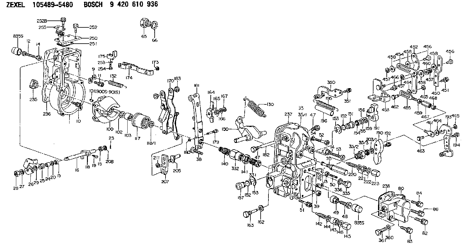
| 1. | [1] | 154004-4621 | GOVERNOR HOUSING |
| 9. | [1] | 154353-5601 | PLATE |
| 10. | [4] | 020106-2040 | BLEEDER SCREW M6P1L20 |
| 11. | [4] | 020106-1840 | BLEEDER SCREW M6P1L18 |
| 12. | [1] | 154010-7300 | BLEEDER SCREW M8P1.25L60 |
| 13. | [1] | 013020-6040 | UNION NUT M6P1H5 |
| 14. | [2] | 154011-2300 | UNION NUT |
| 14. | [2] | 154011-2300 | UNION NUT |
| 15. | [2] | 029620-8050 | PACKING RING |
| 15. | [2] | 029620-8050 | PACKING RING |
| 16. | [1] | 155004-3600 | LEVER SHAFT |
| 18. | [1] | 155003-2401 | CONTROL LEVER |
| 19. | [1] | 155006-0700 | BLEEDER SCREW |
| 20. | [1] | 139308-0900 | PLAIN WASHER D16&8T1 |
| 20B. | [1] | 139308-1000 | PLAIN WASHER D16&8T1.5 |
| 23. | [1] | 025520-1210 | SPLIT PIN |
| 24. | [1] | 154206-5200 | BUSHING |
| 25. | [1] | 154327-9500 | COILED SPRING |
| 26. | [1] | 154381-8100 | CONTROL LEVER |
| 27. | [1] | 014110-8440 | LOCKING WASHER |
| 28. | [1] | 013020-8040 | UNION NUT M8P1.25H7 |
| 29. | [1] | 139408-1400 | SHIM |
| 29B. | [0] | 139408-1400 | SHIM |
| 29C. | [0] | 139408-1500 | SHIM |
| 35. | [1] | 154516-1720 | GOVERNOR COVER |
| 35/1. | [1] | 154516-1700 | GOVERNOR COVER |
| 35/2. | [1] | 154321-2000 | BUSHING |
| 35/3. | [1] | 139610-0600 | PACKING RING |
| 38. | [1] | 154031-3401 | FLAT-HEAD SCREW |
| 39. | [1] | 029201-0160 | UNION NUT |
| 47. | [2] | 154036-1800 | CAPSULE |
| 47. | [2] | 154036-1800 | CAPSULE |
| 48. | [1] | 154010-7100 | BLEEDER SCREW M10P1.25L47 |
| 48B. | [1] | 154010-7700 | BLEEDER SCREW M10P1.25L51 |
| 49. | [1] | 154011-2200 | UNION NUT |
| 50. | [1] | 155615-3500 | FLAT-HEAD SCREW |
| 51. | [5] | 020106-4540 | BLEEDER SCREW M6P1.0L45 |
| 52. | [2] | 029010-6850 | BLEEDER SCREW |
| 53. | [1] | 154010-8100 | BLEEDER SCREW M8P1.25L65 |
| 54. | [2] | 014110-6440 | LOCKING WASHER |
| 65. | [1] | 155404-1700 | CAP |
| 66. | [1] | 026524-3040 | GASKET |
| 70. | [1] | 154055-1520 | HEADLESS SCREW |
| 80. | [1] | 154064-3720 | COVER |
| 82. | [1] | 029020-6210 | BLEEDER SCREW |
| 83. | [1] | 029020-6210 | BLEEDER SCREW |
| 84. | [1] | 020006-1640 | BLEEDER SCREW M6P1L16 4T |
| 86. | [1] | 020006-3540 | BLEEDER SCREW |
| 100. | [1] | 154100-9220 | FLYWEIGHT ASSEMBLY |
| 101. | [1] | 025803-1310 | WOODRUFF KEY |
| 102. | [1] | 029321-2020 | LOCKING WASHER |
| 103. | [1] | 139212-0000 | UNION NUT |
| 117. | [1] | 154123-2320 | SLIDING PIECE |
| 118/1. | [0] | 029311-0010 | SHIM D14&10.1T0.2 |
| 118/1. | [0] | 029311-0180 | SHIM D14&10.1T0.3 |
| 118/1. | [0] | 029311-0190 | SHIM D14&10.1T0.40 |
| 118/1. | [0] | 029311-0210 | SHIM D14&10.1T1 |
| 118/1. | [0] | 139410-0000 | SHIM D14.0&10.1T0.5 |
| 118/1. | [0] | 139410-0100 | SHIM D14.0&10.1T1.5 |
| 118/1. | [0] | 139410-3000 | SHIM D14&10.1T2.0 |
| 118/1. | [0] | 139410-3100 | SHIM D14&10.1T3.0 |
| 118/1. | [0] | 139410-3200 | SHIM D14&10.1T4.0 |
| 130. | [1] | 154150-7900 | GOVERNOR SPRING |
| 132. | [1] | 154154-4600 | COILED SPRING |
| 140. | [1] | 154183-8220 | HEADLESS SCREW |
| 141. | [1] | 139218-0100 | UNION NUT |
| 142. | [1] | 154242-5220 | HEADLESS SCREW |
| 143. | [1] | 154242-5400 | UNION NUT |
| 144. | [1] | 026516-2040 | GASKET D19.9&16.2T1 |
| 145. | [1] | 154159-1800 | CAP NUT |
| 146. | [1] | 029331-6130 | GASKET |
| 150. | [1] | 154200-5401 | SWIVELLING LEVER |
| 151. | [1] | 154200-5501 | BUSHING |
| 152. | [2] | 139700-0000 | O-RING |
| 152. | [2] | 139700-0000 | O-RING |
| 153. | [2] | 154354-3900 | LOCKING WASHER |
| 153. | [2] | 154354-3900 | LOCKING WASHER |
| 154. | [1] | 139610-0101 | PACKING RING |
| 155. | [1] | 139411-0100 | SHIM D22.0&12.0T0.40 |
| 156. | [0] | 139411-0200 | SHIM D18.0&12.0T0.10 |
| 156B. | [0] | 139411-0300 | SHIM D18.0&12.0T0.20 |
| 156C. | [0] | 139411-0400 | SHIM D18.0&12.0T0.30 |
| 157. | [1] | 154204-3500 | BUSHING |
| 159. | [1] | 025803-1310 | WOODRUFF KEY |
| 162. | [1] | 029331-6050 | GASKET |
| 163. | [1] | 154401-3201 | BLEEDER SCREW |
| 164. | [1] | 154243-0720 | CONTROL LEVER |
| 165. | [1] | 154327-6000 | COILED SPRING |
| 166. | [1] | 029310-8320 | SHIM D16.5&8T0.2 |
| 167. | [1] | 154356-3600 | LOCKING WASHER |
| 170. | [1] | 154217-7020 | FORK LEVER |
| 173. | [1] | 016010-0540 | LOCKING WASHER |
| 174. | [1] | 154234-3220 | STRAP |
| 175. | [1] | 154232-2323 | CONNECTOR |
| 179. | [1] | 154238-0201 | BEARING PIN |
| 180. | [1] | 016010-0540 | LOCKING WASHER |
| 181. | [1] | 154239-0420 | TENSIONING LEVER |
| 182. | [1] | 154237-1200 | BEARING PIN |
| 183. | [2] | 154237-1300 | BUSHING |
| 190. | [1] | 154360-2800 | CONTROL LEVER |
| 191. | [1] | 154340-6620 | CONTROL LEVER |
| 192. | [1] | 020006-1670 | BLEEDER SCREW M6P1L16 7T |
| 193. | [1] | 154386-5520 | CONTROL LEVER |
| 194. | [2] | 020006-1240 | BLEEDER SCREW M6P1L12 4T |
| 195. | [2] | 154338-4500 | COILED SPRING |
| 196. | [2] | 154156-1800 | TUBE |
| 203/1. | [0] | 029311-0640 | SHIM D26.0&10.2T0.95 |
| 203/1. | [0] | 029311-0650 | SHIM D26.0&10.2T0.20 |
| 203/1. | [0] | 029311-0660 | SHIM D26.0&10.2T0.25 |
| 203/1. | [0] | 029311-0670 | SHIM D26.0&10.2T0.30 |
| 203/1. | [0] | 029311-0680 | SHIM D26.0&10.2T0.35 |
| 203/1. | [0] | 029311-0690 | SHIM D26.0&10.2T0.40 |
| 203/1. | [0] | 029311-0700 | SHIM D26.0&10.2T0.50 |
| 203/1. | [0] | 139410-1400 | SHIM D26&10.2T0.7 |
| 203/1. | [0] | 139410-1500 | SHIM D26&10.2T0.9 |
| 203/1. | [0] | 139410-1600 | SHIM D26&10.2T0.8 |
| 203/1. | [0] | 139410-2700 | SHIM D26&10.2T0.6 |
| 205. | [1] | 154324-4100 | LEVER SHAFT |
| 207. | [1] | 154326-0300 | CONTROL LEVER |
| 211. | [1] | 016010-0840 | LOCKING WASHER |
| 220. | [1] | 154050-8220 | HEADLESS SCREW |
| 221. | [1] | 029201-2140 | UNION NUT |
| 222. | [2] | 026512-1540 | GASKET D15.4&12.2T1.50 |
| 223. | [1] | 154159-1200 | CAP NUT |
| 235. | [1] | 155412-5200 | IMPELLER WHEEL |
| 236. | [1] | 154371-5600 | GASKET |
| 237. | [1] | 154390-0200 | GASKET |
| 238. | [1] | 154390-1400 | GASKET |
| 250. | [1] | 154063-9800 | COVER |
| 251. | [1] | 154358-2500 | SEAL RING |
| 252. | [2] | 020006-1640 | BLEEDER SCREW M6P1L16 4T |
| 252B. | [2] | 020006-2040 | BLEEDER SCREW M6P1L20 4T |
| 253. | [1] | 029320-5020 | LOCKING WASHER |
| 254. | [1] | 010535-1040 | FLAT-HEAD SCREW M5P0.8L10 |
| 255. | [1] | 154375-0420 | BRACKET |
| 331. | [1] | 154179-9920 | HEADLESS SCREW |
| 332. | [1] | 139218-0200 | UNION NUT |
| 335. | [1] | 154352-2600 | CAPSULE |
| 336. | [1] | 029331-6030 | GASKET |
| 350. | [1] | 154375-3920 | BRACKET |
| 351. | [3] | 029010-5340 | BLEEDER SCREW |
| 360. | [1] | 139512-0700 | GASKET |
| 361. | [1] | 139812-3201 | EYE BOLT |
| 450. | [1] | 154371-6100 | CONTROL LEVER |
| 451. | [2] | 020006-1840 | BLEEDER SCREW M6P1L18 |
| 452. | [1] | 154372-1500 | CONTROL LEVER |
| 453. | [1] | 154371-6321 | BRACKET |
| 454. | [1] | 154372-1300 | STRAP |
| 455. | [1] | 154372-1400 | STRAP |
| 456. | [2] | 154352-1200 | BEARING PIN |
| 456. | [2] | 154352-1200 | BEARING PIN |
| 457. | [3] | 016010-0940 | LOCKING WASHER |
| 457. | [3] | 016010-0940 | LOCKING WASHER |
| 457. | [3] | 016010-0940 | LOCKING WASHER |
| 458. | [5] | 014011-0140 | PLAIN WASHER D22&10.5T1.6 |
| 458. | [5] | 014011-0140 | PLAIN WASHER D22&10.5T1.6 |
| 458. | [5] | 014011-0140 | PLAIN WASHER D22&10.5T1.6 |
| 458. | [5] | 014011-0140 | PLAIN WASHER D22&10.5T1.6 |
| 459. | [1] | 013020-6040 | UNION NUT M6P1H5 |
| 460. | [0] | 029311-0220 | SHIM D18&10.3T0.2 |
| 461. | [1] | 154372-1200 | CONNECTOR |
| 462. | [1] | 159231-5000 | BEARING PIN |
| 463. | [1] | 159231-5100 | BEARING PIN |
| 464. | [2] | 029300-8010 | PLAIN WASHER D15&8T1.00 |
| 464. | [2] | 029300-8010 | PLAIN WASHER D15&8T1.00 |
| 465. | [2] | 016010-0740 | LOCKING WASHER |
| 465. | [2] | 016010-0740 | LOCKING WASHER |
| 466. | [1] | 020118-1440 | BLEEDER SCREW |
| 467. | [1] | 154353-5300 | UNION NUT M6P1H35 |
| 467B. | [1] | 154351-9200 | UNION NUT M6P1H40 |
| 468. | [1] | 029200-6210 | UNION NUT |
| 900S. | [1] | 025803-1310 | WOODRUFF KEY |
| 901S. | [1] | 025803-1610 | WOODRUFF KEY |
Cross reference number
Zexel num
Bosch num
Firm num
Name
Information:
Procedure
Illustration 1 g06220548
(1) TC Mark (Flywheel Housing)
(2) TC Mark (Flywheel)
Remove valve cover, and injector and rocker arm. Bring the piston of cylinder 4 to TDC.
Illustration 2 g06220554
(3) Dial Gauge
(4) Valve
(5) O-ring
Remove the #4 exhaust valve bridge arm and valve spring. Insert a small O-ring (5) so the valve does not fall into the cylinder.
Set dial gauge (3) on the tip of the valve (4).
Illustration 3 g06220569
(6) Tri - Square
(7) Flywheel Housing
(8) Flywheel
Illustration 4 g06220573
(7) Flywheel Housing
(8) Flywheel
(9) Reference Line
Turn the flywheel counterclockwise and measure the position where the tip of the valve is the highest.
Stop the flywheel at the position where the tip of the valve is the highest. Put a tri - square (6) on the flywheel housing (7) and the flywheel (8) and draw a reference line (9).Do not drop the valve (4) into the cylinder. When measuring the highest position of the tip of the valve, do not rotate the flywheel clockwise. If you go past the highest point of the valve, back up the flywheel slightly and measure the highest point of the valve. The reference line (9) indicates the TDC of the crankshaft.
Illustration 5 g06220579
Rotation Sensor Signal Interface Unit
Application: Use for reading rotation sensor signal.
(1) 9V Battery
(2) Switch
(3) 3-Terminal Regulator
(4) LED
(5) Clip (Red)
(6) Clip (Black)
(A) for Panasonic
(B) for Denso
(C) for Bosch cam angle
(D) for Bosch crank angle
((E)) Connector Side
(a) +9 V
(b) Signal
(c) GND
(d) +5 V
(e) Signal
(f) GND
Schematic to build Rotation Sensor Signal Interface.
Illustration 6 g06220581
(10) Rotation Sensor Signal Interface (Tool not available. Schematic to build tool available. Refer to Step 6.
(11) Tester
Illustration 7 g06220587
(12) Ground Terminal
(13) Output Terminal
(14) Crankshaft Position Sensor
Connect a connector of the rotation sensor signal interface unit (10) to the crankshaft position sensor (14). Connect each clip of the rotation sensor signal interface unit (10) to the same test lead color of the tester (11). Switch on the rotation sensor signal interface unit (10).
Illustration 8 g06220590
(15) Pulsar Gear
(16) 14th Tooth
(17) Missing Teeth
Turn the flywheel and make sure that the voltage of the crankshaft position sensor goes from 0→ 5 V or 5 → 0 V.
Rotate the flywheel and align the crankshaft position sensor to the part of the pulsar gear (15) that is missing teeth (17). The 14th tooth (16) from the missing teeth is standard.
Slowly turn flywheel counterclockwise and stop flywheel at the point where needle of the tester changes momentarily from 0 → 5 V, the 14th tooth.That point is where the crankshaft position sensor detects TDC.
Illustration 9 g06220608
(18) Crankshaft TDC
(19) Detection Point of Crankshaft Position Sensor TDC
Illustration 10 g06220612
(20) Interval
Set the tri - square (6) on the reference line (9) on the flywheel housing side and mark the detection point of crankshaft position sensor TDC (19) on the flywheel.
Measure the interval (20) between the crankshaft TDC (18) and the detection point of the crankshaft position sensor TDC (19).
Calculation of fuel injection timing correction 1.0 mm (0.039 in.): 0.321°.Corrected Angle = 0.321° X actual interval
Overwrite the injection timing correction value on the engine ecm registration website refer to REHS9707, "Registering Diesel Particulate Filter (DPF), Diesel Oxidation Catalyst (DOC),