Information governor
BOSCH
9 420 614 375
9420614375
ZEXEL
105489-5390
1054895390
Rating:
Scheme ###:
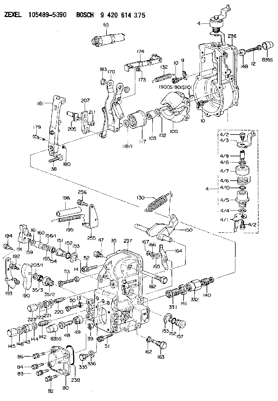
| 1. | [1] | 154000-4700 | GOVERNOR HOUSING |
| 4. | [1] | 154382-0420 | CONTROL LEVER |
| 4. | [1] | 154382-0420 | CONTROL LEVER |
| 4/1. | [1] | 154304-6200 | CONTROL LEVER |
| 4/2. | [2] | 154352-2000 | BLEEDER SCREW |
| 4/2. | [2] | 154352-2000 | BLEEDER SCREW |
| 4/3. | [1] | 154380-0511 | CONTROL LEVER |
| 4/4. | [1] | 029311-0230 | SHIM |
| 4/5. | [1] | 154321-1500 | BUSHING |
| 4/6. | [1] | 154327-6701 | COILED SPRING |
| 4/7. | [1] | 154322-0100 | CAP |
| 4/8. | [1] | 029311-0220 | SHIM |
| 4/9. | [1] | 154324-2700 | LEVER SHAFT |
| 4/10. | [1] | 029631-0030 | O-RING |
| 9. | [1] | 154350-6000 | PLATE |
| 10. | [8] | 020106-2040 | BLEEDER SCREW |
| 10. | [8] | 020106-2040 | BLEEDER SCREW |
| 12. | [1] | 154010-8100 | BLEEDER SCREW |
| 13. | [1] | 013020-6040 | UNION NUT |
| 14. | [1] | 154011-0100 | HEXAGON NUT |
| 14B. | [1] | 154011-2300 | UNION NUT |
| 35. | [1] | 154516-2720 | GOVERNOR COVER |
| 35/2. | [1] | 154321-2300 | BUSHING |
| 35/3. | [1] | 139610-1100 | PACKING RING |
| 38. | [1] | 154031-3500 | FLAT-HEAD SCREW |
| 39. | [1] | 154011-1600 | UNION NUT |
| 47. | [1] | 154036-1200 | CAPSULE |
| 48. | [1] | 154013-0201 | BLEEDER SCREW |
| 48B. | [1] | 154013-0301 | BLEEDER SCREW |
| 49. | [1] | 154011-2200 | UNION NUT |
| 50. | [1] | 155615-1600 | BLEEDER SCREW |
| 51. | [4] | 020106-3840 | BLEEDER SCREW |
| 52. | [2] | 020106-5040 | BLEEDER SCREW |
| 53. | [1] | 154010-2900 | BLEEDER SCREW |
| 65. | [1] | 153021-7220 | STOPPING DEVICE |
| 80. | [1] | 154063-4701 | COVER |
| 82. | [1] | 029020-6210 | BLEEDER SCREW |
| 83. | [1] | 020006-1640 | BLEEDER SCREW |
| 84. | [1] | 029020-6210 | BLEEDER SCREW |
| 86. | [1] | 020006-1640 | BLEEDER SCREW |
| 100. | [1] | 154100-9520 | FLYWEIGHT ASSEMBLY |
| 101. | [1] | 025803-1310 | WOODRUFF KEY 13 MM |
| 102. | [1] | 029321-2020 | LOCKING WASHER |
| 103. | [1] | 029231-2030 | UNION NUT |
| 117. | [1] | 154123-2320 | SLIDING PIECE |
| 118/1. | [0] | 029311-0010 | SHIM D14&10.1T0.2 |
| 118/1. | [0] | 029311-0180 | SHIM D14&10.1T0.3 |
| 118/1. | [0] | 029311-0190 | SHIM D14&10.1T0.40 |
| 118/1. | [0] | 029311-0210 | SHIM D14&10.1T1 |
| 118/1. | [0] | 139410-0000 | SHIM D14&10.1T0.5 |
| 118/1. | [0] | 139410-0100 | SHIM D14&10.1T1.5 |
| 118/1. | [0] | 139410-3000 | SHIM D14&10.1T2.0 |
| 118/1. | [0] | 139410-3100 | SHIM D14&10.1T3.0 |
| 118/1. | [0] | 139410-3200 | SHIM D14&10.1T4.0 |
| 130. | [1] | 154150-6200 | GOVERNOR SPRING |
| 132. | [1] | 154154-4000 | COILED SPRING |
| 140. | [1] | 154180-3920 | HEADLESS SCREW |
| 141. | [1] | 029201-6220 | UNION NUT |
| 142. | [1] | 154242-4720 | HEADLESS SCREW |
| 143. | [1] | 154242-3200 | UNION NUT |
| 144. | [1] | 026516-2040 | GASKET |
| 145. | [1] | 154159-1800 | CAP NUT |
| 146. | [1] | 029331-6130 | GASKET |
| 150. | [1] | 154200-3701 | SWIVELLING LEVER |
| 151. | [1] | 154204-2001 | BUSHING |
| 152. | [2] | 029631-8020 | O-RING |
| 152. | [2] | 029631-8020 | O-RING |
| 153. | [2] | 154354-3900 | LOCKING WASHER |
| 153. | [2] | 154354-3900 | LOCKING WASHER |
| 154. | [1] | 139611-0000 | PACKING RING |
| 155. | [1] | 139411-0000 | SHIM |
| 156/1. | [0] | 029311-1110 | SHIM D17&11T0.1 |
| 156/1. | [0] | 029311-1120 | SHIM D17&11T0.2 |
| 156/1. | [0] | 029311-1130 | SHIM D17&11T0.3 |
| 157. | [1] | 154204-3400 | BUSHING |
| 159. | [1] | 025803-1310 | WOODRUFF KEY 13 MM |
| 160. | [1] | 154206-0900 | BUSHING |
| 161. | [1] | 154206-0200 | PLAIN WASHER |
| 162. | [1] | 029331-6050 | GASKET |
| 163. | [1] | 154401-3401 | BLEEDER SCREW |
| 164. | [1] | 154243-0620 | CONTROL LEVER |
| 165. | [1] | 154327-5400 | COILED SPRING |
| 166. | [1] | 029310-8320 | SHIM |
| 167. | [1] | 154356-3600 | LOCKING WASHER |
| 170. | [1] | 154218-1320 | FORK LEVER |
| 173. | [1] | 016010-0540 | LOCKING WASHER |
| 174. | [1] | 154230-4920 | STRAP |
| 179. | [1] | 154238-0301 | BEARING PIN |
| 180. | [1] | 016010-0540 | LOCKING WASHER |
| 181. | [1] | 154239-3120 | TENSIONING LEVER |
| 182. | [1] | 154237-0900 | BEARING PIN |
| 183. | [2] | 154237-0600 | BUSHING |
| 190. | [1] | 154360-2700 | CONTROL LEVER |
| 191. | [1] | 154340-5321 | CONTROL LEVER |
| 192. | [1] | 020006-1670 | BLEEDER SCREW |
| 193. | [1] | 154369-7220 | CONTROL LEVER |
| 194. | [2] | 020006-1240 | BLEEDER SCREW |
| 195. | [2] | 154317-8200 | COILED SPRING |
| 196. | [2] | 154156-3000 | TUBE |
| 203/1. | [0] | 139410-0200 | SHIM D32&10.2T0.1 |
| 203/1. | [0] | 139410-0300 | SHIM D32&10.2T0.3 |
| 203/1. | [0] | 139410-0400 | SHIM D32&10.2T0.5 |
| 203/1. | [0] | 139410-0500 | SHIM D32&10.2T0.9 |
| 205. | [1] | 154324-3100 | LEVER SHAFT |
| 207. | [1] | 154326-0300 | CONTROL LEVER |
| 211. | [1] | 016010-0840 | LOCKING WASHER |
| 220. | [1] | 154050-6820 | HEADLESS SCREW |
| 221. | [1] | 029201-2130 | UNION NUT |
| 222. | [2] | 026512-1540 | GASKET |
| 223. | [1] | 154159-1200 | CAP NUT |
| 236. | [1] | 154371-5600 | GASKET |
| 237. | [1] | 154390-0300 | GASKET |
| 238. | [1] | 029635-2020 | O-RING |
| 255. | [1] | 154372-6220 | BRACKET |
| 256. | [2] | 020006-1240 | BLEEDER SCREW |
| 331. | [1] | 154179-3020 | HEADLESS SCREW |
| 332. | [1] | 029201-6010 | UNION NUT |
| 335. | [1] | 154352-2600 | CAPSULE |
| 336. | [1] | 029331-6030 | GASKET |
| 835S. | [2] | 154062-1700 | CAP |
| 835S. | [2] | 154062-1700 | CAP |
| 900S. | [1] | 025803-1310 | WOODRUFF KEY 13 MM |
| 901S. | [1] | 025803-1610 | WOODRUFF KEY 16 MM |
Include in #1:
106871-4341
as GOVERNOR
Cross reference number
Zexel num
Bosch num
Firm num
Name
Information:
Introduction
Do not perform any procedure in this Special Instruction until you read this information and you understand this information.This Special Instruction provides the following information for 3600 Diesel Engines:
Identification of a service tool
A procedure to check cylinder pressureService Tool
Illustration 1 g01250874
4C-6585 Indicator Group (1) Hand tool for tightening gauge connectionProcedure for Checking Cylinder Pressure
Take the readings for cylinder pressure at the rated speed and at the rated load in order to obtain the peak cylinder pressure for a specific rating.Readings for cylinder pressure can also be taken at a light load condition or at a no-load condition. These pressure readings can be used as a baseline for a comparison at a later date. For a valid comparison, pressure measurements that are taken at a later date must duplicate the initial load conditions.
Illustration 2 g01250892
(2) Cylinder pressure valve (Kiene valve) (3) Valve stem (4) Cap
Remove cap (4) from valve (2) .
Fluids may escape from the cylinder pressure valves at high velocity during this procedure and cause personal injury. Always stay clear and keep personnel away from the cylinder pressure valves during this procedure.
Stand to the side of the valve and open valve stem (3) approximately 90° (1/4 turn) counterclockwise. Close valve stem (3). This will blow any foreign debris out of the valve.
Illustration 3 g01250917
(5) 4C-9736 Pressure Gauge (6) 4C-9737 Gauge connection
Install the 4C-6585 Indicator group on the valve. Use tool (1) that is provided in the indicator group in order to tighten gauge connection (6) to a torque of 17 3 N m (12 2 lb ft). Do not overtighten the gauge connection.
Open valve stem (3) by approximately 540° (1 1/2 turn) counterclockwise. Document the reading on pressure gauge (5) and close valve stem (3). Tighten the valve stem to a torque of 24 3 N m (18 2 lb ft). Do not overtighten the valve stem.
Use the hand tool that is provided in the indicator group in order to loosen the gauge connection. Remove the 4C-6585 Indicator Group .
Install cap (4). Tighten to a torque of 17 3 N m (12 2 lb ft). Do not overtighten the cap.