Information governor
BOSCH
9 420 610 638
9420610638
ZEXEL
105489-4434
1054894434

Rating:
Scheme ###:
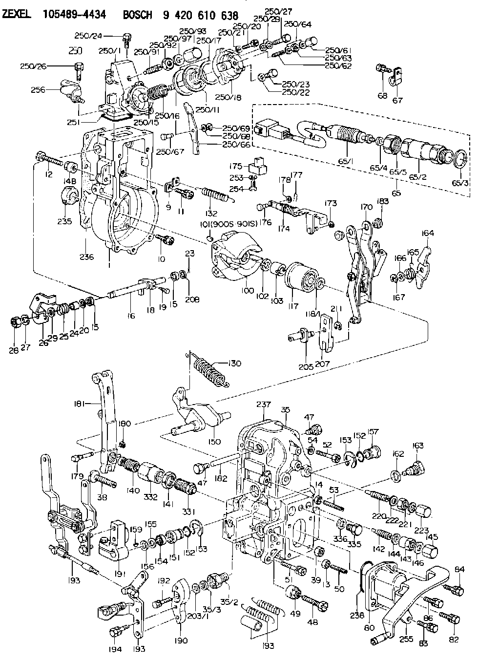
| 1. | [1] | 154004-6420 | GOVERNOR HOUSING |
| 9. | [1] | 154350-6000 | PLATE |
| 10. | [4] | 139006-4100 | BLEEDER SCREW |
| 11. | [4] | 139006-5800 | BLEEDER SCREW |
| 12. | [1] | 154010-7300 | BLEEDER SCREW M8P1.25L60 |
| 13. | [1] | 013020-6040 | UNION NUT M6P1H5 |
| 14. | [1] | 154011-0100 | HEXAGON NUT |
| 14B. | [1] | 154011-2300 | UNION NUT |
| 15. | [2] | 139608-0000 | PACKING RING |
| 15. | [2] | 139608-0000 | PACKING RING |
| 16. | [1] | 155004-3600 | LEVER SHAFT |
| 18. | [1] | 155003-3401 | CONTROL LEVER |
| 19. | [1] | 155006-0700 | BLEEDER SCREW |
| 20. | [1] | 139308-0900 | PLAIN WASHER D16&8T1 |
| 20B. | [1] | 139308-1000 | PLAIN WASHER D16&8T1.5 |
| 23. | [1] | 025520-1210 | SPLIT PIN |
| 24. | [1] | 154206-5200 | BUSHING |
| 25. | [1] | 154327-9500 | COILED SPRING |
| 26. | [1] | 154381-2900 | CONTROL LEVER |
| 27. | [1] | 014110-8440 | LOCKING WASHER |
| 28. | [1] | 013020-8040 | UNION NUT M8P1.25H7 |
| 29. | [1] | 139408-1400 | SHIM |
| 29B. | [0] | 139408-1400 | SHIM |
| 29C. | [0] | 139408-1500 | SHIM |
| 35. | [1] | 154516-1420 | GOVERNOR COVER |
| 35/2. | [1] | 154321-2000 | BUSHING |
| 35/3. | [1] | 139610-0600 | PACKING RING |
| 38. | [1] | 154031-3401 | FLAT-HEAD SCREW |
| 39. | [1] | 029201-0160 | UNION NUT |
| 47. | [2] | 154036-1800 | CAPSULE |
| 47. | [2] | 154036-1800 | CAPSULE |
| 48. | [1] | 154010-7900 | BLEEDER SCREW M10P1.25L58 |
| 48B. | [1] | 154010-5600 | BLEEDER SCREW M10P1.25L60 |
| 49. | [1] | 154011-2200 | UNION NUT |
| 50. | [1] | 155615-2300 | FLAT-HEAD SCREW |
| 51. | [5] | 020106-4540 | BLEEDER SCREW M6P1.0L45 |
| 52. | [2] | 029010-6850 | BLEEDER SCREW |
| 53. | [1] | 154010-1100 | FLAT-HEAD SCREW |
| 54. | [2] | 014110-6440 | LOCKING WASHER |
| 65. | [1] | 154610-7520 | RACK SENSOR ASSY |
| 65/1. | [1] | 479742-5320 | RACK SENSOR |
| 65/2. | [1] | 154614-4700 | JOINT CONNECTION |
| 65/3. | [1] | 026524-3040 | GASKET |
| 65/4A. | [0] | 029310-6220 | SHIM D11.5&6.5T0.10 |
| 65/4B. | [0] | 029310-6230 | SHIM D11.5&6.5T0.20 |
| 65/4C. | [0] | 029310-6240 | SHIM D11.5&6.5T0.25 |
| 65/4D. | [0] | 029310-6260 | SHIM D11.5&6.4T1.00 |
| 65/4E. | [0] | 029310-6270 | SHIM D11.5&6.4T1.20 |
| 65/4F. | [0] | 029310-6280 | SHIM D11.5&6.4T1.50 |
| 65/5. | [1] | 154614-1900 | UNION NUT |
| 67. | [1] | 154614-3600 | CLAMPING BAND |
| 68. | [1] | 020106-1240 | BLEEDER SCREW M6P1.0L12 |
| 80. | [1] | 154063-9100 | COVER |
| 82. | [1] | 029020-6210 | BLEEDER SCREW |
| 83. | [1] | 029020-6240 | BLEEDER SCREW |
| 84. | [1] | 020006-1840 | BLEEDER SCREW M6P1L18 |
| 86. | [1] | 020006-1840 | BLEEDER SCREW M6P1L18 |
| 100. | [1] | 154100-9320 | FLYWEIGHT ASSEMBLY |
| 101. | [1] | 025803-1310 | WOODRUFF KEY |
| 102. | [1] | 029321-2020 | LOCKING WASHER |
| 103. | [1] | 139212-0000 | UNION NUT |
| 117. | [1] | 154123-2320 | SLIDING PIECE |
| 118/1. | [0] | 029311-0010 | SHIM D14&10.1T0.2 |
| 118/1. | [0] | 029311-0180 | SHIM D14&10.1T0.3 |
| 118/1. | [0] | 029311-0190 | SHIM D14&10.1T0.40 |
| 118/1. | [0] | 029311-0210 | SHIM D14&10.1T1 |
| 118/1. | [0] | 139410-0000 | SHIM D14.0&10.1T0.5 |
| 118/1. | [0] | 139410-0100 | SHIM D14.0&10.1T1.5 |
| 118/1. | [0] | 139410-3000 | SHIM D14&10.1T2.0 |
| 118/1. | [0] | 139410-3100 | SHIM D14&10.1T3.0 |
| 118/1. | [0] | 139410-3200 | SHIM D14&10.1T4.0 |
| 130. | [1] | 154150-7900 | GOVERNOR SPRING |
| 132. | [1] | 154154-0701 | COILED SPRING |
| 140. | [1] | 154183-0320 | HEADLESS SCREW |
| 141. | [1] | 139218-0100 | UNION NUT |
| 142. | [1] | 154242-5720 | HEADLESS SCREW |
| 143. | [1] | 154242-3200 | UNION NUT |
| 144. | [1] | 026516-2040 | GASKET D19.9&16.2T1 |
| 145. | [1] | 154159-1800 | CAP NUT |
| 146. | [1] | 029331-6130 | GASKET |
| 150. | [1] | 154200-5601 | SWIVELLING LEVER |
| 151. | [1] | 154200-5501 | BUSHING |
| 152. | [2] | 139700-0000 | O-RING |
| 152. | [2] | 139700-0000 | O-RING |
| 153. | [2] | 154354-3900 | LOCKING WASHER |
| 153. | [2] | 154354-3900 | LOCKING WASHER |
| 154. | [1] | 139610-0101 | PACKING RING |
| 155. | [1] | 139411-0100 | SHIM D22.0&12.0T0.40 |
| 156. | [0] | 139411-0200 | SHIM D18.0&12.0T0.10 |
| 156B. | [0] | 139411-0300 | SHIM D18.0&12.0T0.20 |
| 156C. | [0] | 139411-0400 | SHIM D18.0&12.0T0.30 |
| 157. | [1] | 154204-3500 | BUSHING |
| 159. | [1] | 025803-1310 | WOODRUFF KEY |
| 162. | [1] | 029331-6050 | GASKET |
| 163. | [1] | 154401-3201 | BLEEDER SCREW |
| 164. | [1] | 154243-0820 | CONTROL LEVER |
| 165. | [1] | 154327-6100 | COILED SPRING |
| 166. | [1] | 029310-8320 | SHIM D16.5&8T0.2 |
| 167. | [1] | 154356-3600 | LOCKING WASHER |
| 170. | [1] | 154218-3620 | FORK LEVER |
| 173. | [1] | 016010-0540 | LOCKING WASHER |
| 174. | [1] | 154235-0720 | STRAP |
| 175. | [1] | 154232-2323 | CONNECTOR |
| 176. | [1] | 159231-4900 | BEARING PIN |
| 177. | [1] | 155402-3800 | SAFETY PIN |
| 178. | [1] | 029310-5170 | SHIM D8&5.3T0.5 |
| 179. | [1] | 154238-0701 | BEARING PIN |
| 180. | [1] | 016010-0540 | LOCKING WASHER |
| 181. | [1] | 154239-2320 | TENSIONING LEVER |
| 182. | [1] | 154237-1200 | BEARING PIN |
| 183. | [2] | 154237-1800 | BUSHING |
| 190. | [1] | 154360-2700 | CONTROL LEVER |
| 191. | [1] | 154340-4620 | CONTROL LEVER |
| 192. | [1] | 020006-1670 | BLEEDER SCREW M6P1L16 7T |
| 193. | [1] | 154399-6520 | LEVER GROUP |
| 193. | [1] | 154399-6520 | LEVER GROUP |
| 193. | [1] | 154399-6520 | LEVER GROUP |
| 194. | [2] | 020006-1240 | BLEEDER SCREW M6P1L12 4T |
| 203/1. | [0] | 029311-0640 | SHIM D26.0&10.2T0.95 |
| 203/1. | [0] | 029311-0650 | SHIM D26.0&10.2T0.20 |
| 203/1. | [0] | 029311-0660 | SHIM D26.0&10.2T0.25 |
| 203/1. | [0] | 029311-0670 | SHIM D26.0&10.2T0.30 |
| 203/1. | [0] | 029311-0680 | SHIM D26.0&10.2T0.35 |
| 203/1. | [0] | 029311-0690 | SHIM D26.0&10.2T0.40 |
| 203/1. | [0] | 029311-0700 | SHIM D26.0&10.2T0.50 |
| 203/1. | [0] | 139410-1400 | SHIM D26&10.2T0.7 |
| 203/1. | [0] | 139410-1500 | SHIM D26&10.2T0.9 |
| 203/1. | [0] | 139410-1600 | SHIM D26&10.2T0.8 |
| 203/1. | [0] | 139410-2700 | SHIM D26&10.2T0.6 |
| 205. | [1] | 154324-3600 | LEVER SHAFT |
| 207. | [1] | 154326-8220 | CONTROL LEVER |
| 211. | [1] | 016010-0840 | LOCKING WASHER |
| 220. | [1] | 154050-8220 | HEADLESS SCREW |
| 221. | [1] | 029201-2140 | UNION NUT |
| 222. | [2] | 026512-1540 | GASKET D15.4&12.2T1.50 |
| 223. | [1] | 154159-1200 | CAP NUT |
| 235. | [1] | 155412-5200 | IMPELLER WHEEL |
| 236. | [1] | 154413-2900 | GASKET |
| 237. | [1] | 154390-0200 | GASKET |
| 238. | [1] | 139700-0100 | O-RING |
| 250. | [1] | 154420-0620 | MANIFOLD-PRESSURE COMP. |
| 250/1. | [1] | 154412-5822 | DIAPHRAGM HOUSING |
| 250/11. | [1] | 154412-6522 | DIAPHRAGM |
| 250/15. | [1] | 154412-7700 | BUSHING |
| 250/16. | [1] | 154411-3800 | COILED SPRING |
| 250/17. | [2] | 154413-2600 | GASKET |
| 250/18. | [1] | 154404-3900 | COVER |
| 250/20. | [3] | 139006-0900 | BLEEDER SCREW |
| 250/21. | [3] | 014110-6440 | LOCKING WASHER |
| 250/22. | [1] | 026506-1040 | GASKET D9.9&6.2T1 |
| 250/23. | [1] | 029010-6010 | CAPSULE M6P1.0L7 |
| 250/24. | [2] | 020106-1640 | BLEEDER SCREW M6P1.0L14 |
| 250/26. | [2] | 020106-2040 | BLEEDER SCREW M6P1L20 |
| 250/27. | [1] | 029731-0180 | EYE BOLT |
| 250/28. | [2] | 026510-1340 | GASKET D13.4&10.2T1 |
| 250/61. | [1] | 154035-1600 | CAP NUT |
| 250/62. | [1] | 154404-4400 | FLAT-HEAD SCREW |
| 250/63. | [1] | 013030-6040 | UNION NUT M6P1H3.6 |
| 250/64. | [2] | 026506-1040 | GASKET D9.9&6.2T1 |
| 250/66. | [1] | 154412-4622 | CONTROL LEVER |
| 250/67. | [1] | 154412-1600 | BEARING PIN |
| 250/68. | [1] | 029310-5090 | SHIM D10&5.1T0.5 |
| 250/69. | [1] | 016010-0540 | LOCKING WASHER |
| 250/91. | [1] | 154412-5120 | HEADLESS SCREW |
| 250/92. | [1] | 029201-2030 | UNION NUT M12P1.0H4 |
| 250/93. | [1] | 154412-5300 | CAP NUT |
| 250/97. | [2] | 026512-1540 | GASKET D15.4&12.2T1.50 |
| 251. | [1] | 154358-2500 | SEAL RING |
| 253. | [1] | 029320-5020 | LOCKING WASHER |
| 254. | [1] | 010535-1040 | FLAT-HEAD SCREW M5P0.8L10 |
| 255. | [1] | 154375-2920 | BRACKET |
| 256. | [1] | 154373-8420 | BRACKET |
| 331. | [1] | 154179-5020 | HEADLESS SCREW |
| 332. | [1] | 139218-0500 | UNION NUT |
| 335. | [1] | 154352-2600 | CAPSULE |
| 336. | [1] | 029331-6030 | GASKET |
| 900S. | [1] | 025803-1310 | WOODRUFF KEY |
| 901S. | [1] | 025803-1610 | WOODRUFF KEY |
Cross reference number
Zexel num
Bosch num
Firm num
Name
Information:
Test Procedure
System Operation
The SLC 5/04 diagnostic indicators are located on the front of the following components: Power Supply, CPU and I/O Modules.The diagnostic indicators help trace the source of the fault. Faults can be found in the following components: Input devices, Output devices, Wiring and The controller.
Illustration 1 g00563535
Diagram of the LED indicators
Illustration 2 g00562937
Functional Test
Check the electrical connectors and check the wiring.
Bodily contact with electrical potential can cause bodily injury or death.To avoid the possibility of injury or death, ensure that the main power supply has been disconnected before performing any maintenance or removing any modules.
Disconnect the power supply.
Check the electrical connectors and check the wiring for damage or bad connections.
Verify that all modules are properly seated.
Connect the power supply.
Verify the status of the LED on the SLC 5/04.The results of the preceding procedure are in the following list:
All of the components are fully installed. All of the components are free of corrosion. All of the components are free of damage. All of the modules are properly seated. Proceed to 2.
The components are not fully installed. The components are not free of corrosion. The components are damaged. All of the modules are not properly seated. Repair the component. Verify that the repair resolves the problem. STOP.
Check the line voltage.
Reconnect the power supply.
Measure the line voltage at the terminals.
Verify the voltage of the power supply. The power supply voltage should be measured between 21.0 VDC and 28.0 VDC.The results of the preceding procedure are in the following list:
The line voltage is in the range. Proceed to 3.
The line voltage is out of the range. Refer to Troubleshooting, "System Power". Stop.
Attempt to operate the processor in the "RUN" mode.
Place the switch in the RUN position.The results of the preceding procedure are in the following list:
The processor enters the "RUN" mode. The processor resumes normal operation. Stop.
The processor will not enter the "RUN" mode. Proceed to 4.
Check the processor.
To avoid damage to electronic components, do not remove the processor from the SLC 5/04 Chassis until all power is removed from the power supply.Do not expose memory modules to surfaces or areas that may typically hold an electrostatic charge.
Bodily contact with electrical potential can cause bodily injury or death.To avoid the possibility of injury or death, ensure that the main power supply has been disconnected before performing any maintenance or removing any modules.
Disconnect the power supply.
Remove the processor from the chassis.
Install the processor in another chassis.
Connect the power supply.
Configure the power supply.
Attempt to operate the processor in the "RUN" mode.The results of the preceding procedure are in the following list:
The processor enters the "RUN" mode. The processor will not perform functions in the run mode. Replace the chassis. Verify that the repair solves the problem. Stop.
The processor will not enter the "RUN" mode. Replace the processor. Refer to Maintenance Procedure, "Processor - Replace".