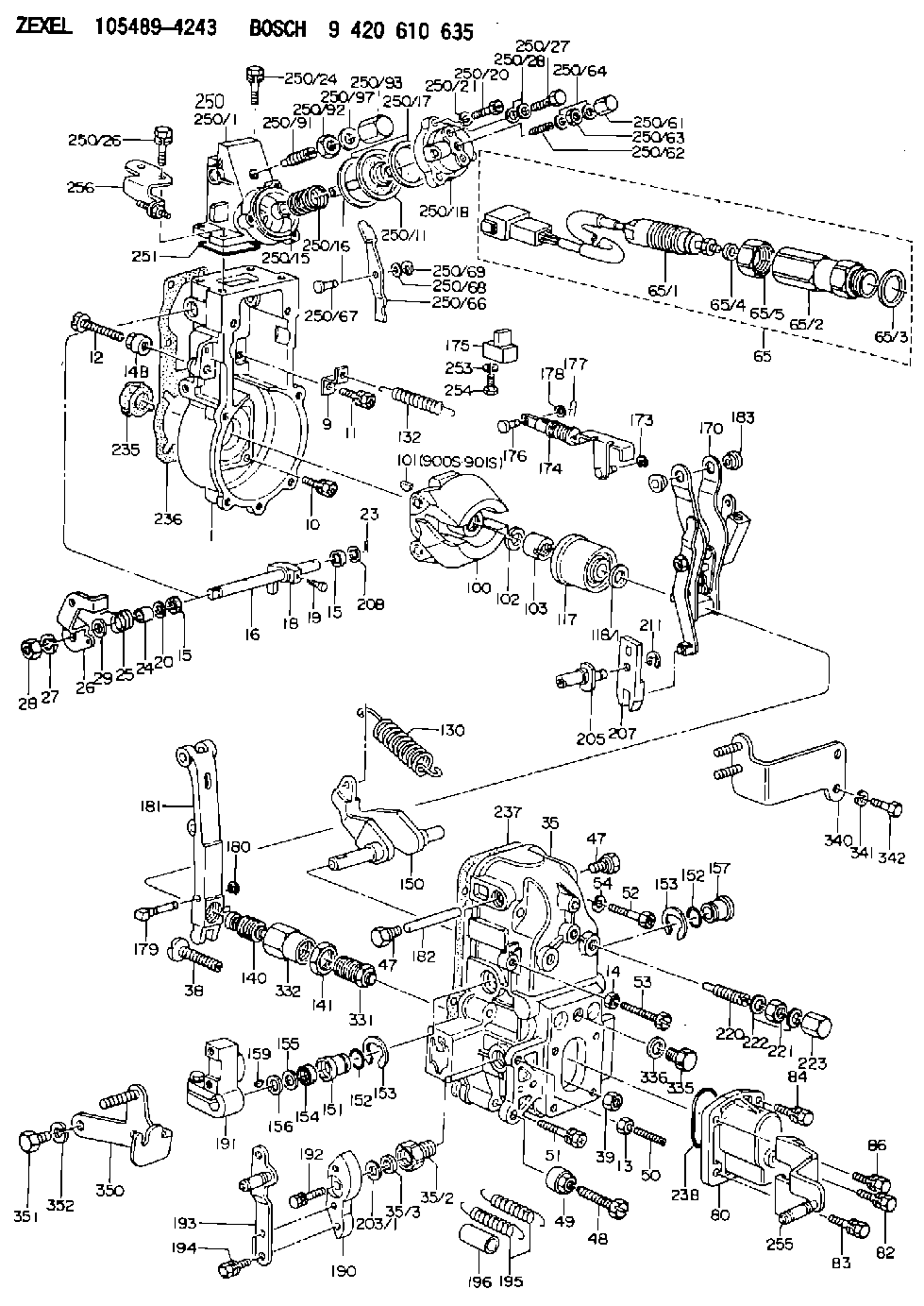
Information governor
BOSCH
9 420 610 635
9420610635
ZEXEL
105489-4243
1054894243

Rating:
Scheme ###:
| 1. | [1] | 154004-6420 | GOVERNOR HOUSING |
| 9. | [1] | 154350-6000 | PLATE |
| 10. | [4] | 139006-4100 | BLEEDER SCREW |
| 11. | [4] | 139006-5800 | BLEEDER SCREW |
| 12. | [1] | 154010-7300 | BLEEDER SCREW M8P1.25L60 |
| 13. | [1] | 013020-6040 | UNION NUT M6P1H5 |
| 14. | [1] | 154011-0100 | HEXAGON NUT |
| 14B. | [1] | 154011-2300 | UNION NUT |
| 15. | [2] | 139608-0000 | PACKING RING |
| 15. | [2] | 139608-0000 | PACKING RING |
| 16. | [1] | 155004-3600 | LEVER SHAFT |
| 18. | [1] | 155003-3401 | CONTROL LEVER |
| 19. | [1] | 155006-0700 | BLEEDER SCREW |
| 20. | [1] | 139308-1500 | PLAIN WASHER D18&8T1.0 |
| 20B. | [1] | 139308-1600 | PLAIN WASHER D18&8T1.5 |
| 23. | [1] | 154373-2200 | SAFETY PIN |
| 24. | [1] | 154206-5200 | BUSHING |
| 25. | [1] | 154327-9500 | COILED SPRING |
| 26. | [1] | 154381-6800 | CONTROL LEVER |
| 27. | [1] | 014110-8440 | LOCKING WASHER |
| 28. | [1] | 013020-8040 | UNION NUT M8P1.25H7 |
| 29. | [1] | 139408-1400 | SHIM |
| 29B. | [0] | 139408-1400 | SHIM |
| 29C. | [0] | 139408-1500 | SHIM |
| 35. | [1] | 154516-1620 | GOVERNOR COVER |
| 35/2. | [1] | 154321-2000 | BUSHING |
| 35/3. | [1] | 139610-0600 | PACKING RING |
| 38. | [1] | 154031-3401 | FLAT-HEAD SCREW |
| 39. | [1] | 029201-0160 | UNION NUT |
| 47. | [2] | 154036-1800 | CAPSULE |
| 47. | [2] | 154036-1800 | CAPSULE |
| 48. | [1] | 154010-7900 | BLEEDER SCREW M10P1.25L58 |
| 48B. | [1] | 154010-6000 | BLEEDER SCREW M10P1.25L55 |
| 49. | [1] | 154011-2200 | UNION NUT |
| 50. | [1] | 155615-2300 | FLAT-HEAD SCREW |
| 51. | [5] | 020106-4540 | BLEEDER SCREW M6P1.0L45 |
| 52. | [2] | 029010-6850 | BLEEDER SCREW |
| 53. | [1] | 154010-3100 | BLEEDER SCREW |
| 54. | [2] | 014110-6440 | LOCKING WASHER |
| 65. | [1] | 154610-8820 | RACK SENSOR ASSY |
| 65/1. | [1] | 479742-7120 | RACK SENSOR |
| 65/2. | [1] | 154614-6800 | JOINT CONNECTION |
| 65/3. | [1] | 026524-3040 | GASKET |
| 65/4A. | [0] | 029310-6220 | SHIM D11.5&6.5T0.10 |
| 65/4B. | [0] | 029310-6230 | SHIM D11.5&6.5T0.20 |
| 65/4C. | [0] | 029310-6240 | SHIM D11.5&6.5T0.25 |
| 65/4D. | [0] | 029310-6260 | SHIM D11.5&6.4T1.00 |
| 65/4E. | [0] | 029310-6270 | SHIM D11.5&6.4T1.20 |
| 65/4F. | [0] | 029310-6280 | SHIM D11.5&6.4T1.50 |
| 65/5. | [1] | 154614-1900 | UNION NUT |
| 80. | [1] | 154063-9100 | COVER |
| 82. | [1] | 029020-6210 | BLEEDER SCREW |
| 83. | [1] | 029020-6240 | BLEEDER SCREW |
| 84. | [1] | 020006-1640 | BLEEDER SCREW M6P1L16 4T |
| 86. | [1] | 020006-1840 | BLEEDER SCREW M6P1L18 |
| 100. | [1] | 154100-9320 | FLYWEIGHT ASSEMBLY |
| 101. | [1] | 025803-1310 | WOODRUFF KEY |
| 102. | [1] | 029321-2020 | LOCKING WASHER |
| 103. | [1] | 139212-0000 | UNION NUT |
| 117. | [1] | 154123-2320 | SLIDING PIECE |
| 118/1. | [0] | 029311-0010 | SHIM D14&10.1T0.2 |
| 118/1. | [0] | 029311-0180 | SHIM D14&10.1T0.3 |
| 118/1. | [0] | 029311-0190 | SHIM D14&10.1T0.40 |
| 118/1. | [0] | 029311-0210 | SHIM D14&10.1T1 |
| 118/1. | [0] | 139410-0000 | SHIM D14.0&10.1T0.5 |
| 118/1. | [0] | 139410-0100 | SHIM D14.0&10.1T1.5 |
| 118/1. | [0] | 139410-3000 | SHIM D14&10.1T2.0 |
| 118/1. | [0] | 139410-3100 | SHIM D14&10.1T3.0 |
| 118/1. | [0] | 139410-3200 | SHIM D14&10.1T4.0 |
| 130. | [1] | 154150-7900 | GOVERNOR SPRING |
| 132. | [1] | 154154-0701 | COILED SPRING |
| 140. | [1] | 154183-0020 | HEADLESS SCREW |
| 141. | [1] | 139218-0100 | UNION NUT |
| 150. | [1] | 154200-5601 | SWIVELLING LEVER |
| 151. | [1] | 154200-5501 | BUSHING |
| 152. | [2] | 139700-0000 | O-RING |
| 152. | [2] | 139700-0000 | O-RING |
| 153. | [2] | 154354-3900 | LOCKING WASHER |
| 153. | [2] | 154354-3900 | LOCKING WASHER |
| 154. | [1] | 139610-0101 | PACKING RING |
| 155. | [1] | 139411-0100 | SHIM D22.0&12.0T0.40 |
| 156. | [0] | 139411-0200 | SHIM D18.0&12.0T0.10 |
| 156B. | [0] | 139411-0300 | SHIM D18.0&12.0T0.20 |
| 156C. | [0] | 139411-0400 | SHIM D18.0&12.0T0.30 |
| 157. | [1] | 154204-3500 | BUSHING |
| 159. | [1] | 025803-1310 | WOODRUFF KEY |
| 170. | [1] | 154218-4620 | FORK LEVER |
| 173. | [1] | 016010-0540 | LOCKING WASHER |
| 174. | [1] | 154234-8220 | STRAP |
| 175. | [1] | 154232-1923 | CONNECTOR |
| 176. | [1] | 159231-4900 | BEARING PIN |
| 177. | [1] | 155402-3800 | SAFETY PIN |
| 178. | [1] | 029310-5170 | SHIM D8&5.3T0.5 |
| 179. | [1] | 154238-0701 | BEARING PIN |
| 180. | [1] | 016010-0540 | LOCKING WASHER |
| 181. | [1] | 154239-1120 | TENSIONING LEVER |
| 182. | [1] | 154237-1200 | BEARING PIN |
| 183. | [2] | 154237-1800 | BUSHING |
| 190. | [1] | 154360-2700 | CONTROL LEVER |
| 191. | [1] | 154340-4520 | CONTROL LEVER |
| 192. | [1] | 020006-1670 | BLEEDER SCREW M6P1L16 7T |
| 193. | [1] | 154386-1320 | CONTROL LEVER |
| 194. | [2] | 020006-1240 | BLEEDER SCREW M6P1L12 4T |
| 195. | [2] | 154332-9600 | COILED SPRING |
| 196. | [2] | 154156-2900 | TUBE |
| 203/1. | [0] | 029311-0640 | SHIM D26.0&10.2T0.95 |
| 203/1. | [0] | 029311-0650 | SHIM D26.0&10.2T0.20 |
| 203/1. | [0] | 029311-0660 | SHIM D26.0&10.2T0.25 |
| 203/1. | [0] | 029311-0670 | SHIM D26.0&10.2T0.30 |
| 203/1. | [0] | 029311-0680 | SHIM D26.0&10.2T0.35 |
| 203/1. | [0] | 029311-0690 | SHIM D26.0&10.2T0.40 |
| 203/1. | [0] | 029311-0700 | SHIM D26.0&10.2T0.50 |
| 203/1. | [0] | 139410-1400 | SHIM D26&10.2T0.7 |
| 203/1. | [0] | 139410-1500 | SHIM D26&10.2T0.9 |
| 203/1. | [0] | 139410-1600 | SHIM D26&10.2T0.8 |
| 203/1. | [0] | 139410-2700 | SHIM D26&10.2T0.6 |
| 205. | [1] | 154324-3600 | LEVER SHAFT |
| 207. | [1] | 154326-8220 | CONTROL LEVER |
| 211. | [1] | 016010-0840 | LOCKING WASHER |
| 220. | [1] | 154050-8620 | HEADLESS SCREW |
| 221. | [1] | 029201-2140 | UNION NUT |
| 222. | [2] | 026512-1540 | GASKET D15.4&12.2T1.50 |
| 223. | [1] | 154159-1200 | CAP NUT |
| 235. | [1] | 155412-5300 | IMPELLER WHEEL |
| 236. | [1] | 154413-2900 | GASKET |
| 237. | [1] | 154390-0200 | GASKET |
| 238. | [1] | 139700-0100 | O-RING |
| 250. | [1] | 154419-2620 | MANIFOLD-PRESSURE COMP. |
| 250/1. | [1] | 154412-5822 | DIAPHRAGM HOUSING |
| 250/11. | [1] | 154412-6522 | DIAPHRAGM |
| 250/15. | [1] | 154412-7700 | BUSHING |
| 250/16. | [1] | 154411-5500 | COILED SPRING |
| 250/17. | [2] | 154413-2600 | GASKET |
| 250/18. | [1] | 154404-5000 | COVER |
| 250/20. | [3] | 139006-0900 | BLEEDER SCREW |
| 250/21. | [3] | 014110-6440 | LOCKING WASHER |
| 250/24. | [2] | 020106-1640 | BLEEDER SCREW M6P1.0L14 |
| 250/26. | [2] | 020106-2040 | BLEEDER SCREW M6P1L20 |
| 250/27. | [1] | 029731-0180 | EYE BOLT |
| 250/28. | [2] | 026510-1340 | GASKET D13.4&10.2T1 |
| 250/61. | [1] | 154035-1600 | CAP NUT |
| 250/62. | [1] | 154404-4400 | FLAT-HEAD SCREW |
| 250/63. | [1] | 013030-6040 | UNION NUT M6P1H3.6 |
| 250/64. | [2] | 026506-1040 | GASKET D9.9&6.2T1 |
| 250/66. | [1] | 154412-4622 | CONTROL LEVER |
| 250/67. | [1] | 154412-1600 | BEARING PIN |
| 250/68. | [1] | 029310-5090 | SHIM D10&5.1T0.5 |
| 250/69. | [1] | 016010-0540 | LOCKING WASHER |
| 250/91. | [1] | 154412-5120 | HEADLESS SCREW |
| 250/92. | [1] | 029201-2030 | UNION NUT M12P1.0H4 |
| 250/93. | [1] | 154412-5300 | CAP NUT |
| 250/97. | [2] | 026512-1540 | GASKET D15.4&12.2T1.50 |
| 251. | [1] | 154358-2500 | SEAL RING |
| 253. | [1] | 029320-5020 | LOCKING WASHER |
| 254. | [1] | 010535-1040 | FLAT-HEAD SCREW M5P0.8L10 |
| 255. | [1] | 154374-8620 | BRACKET |
| 256. | [1] | 154373-7120 | BRACKET |
| 331. | [1] | 154188-3720 | HEADLESS SCREW |
| 332. | [1] | 139218-0500 | UNION NUT |
| 335. | [1] | 154352-2600 | CAPSULE |
| 336. | [1] | 029331-6030 | GASKET |
| 340. | [1] | 154372-7820 | BRACKET |
| 341. | [2] | 014110-8440 | LOCKING WASHER |
| 342. | [2] | 010038-1240 | BLEEDER SCREW |
| 350. | [1] | 154373-0020 | BRACKET |
| 351. | [2] | 010010-1640 | BLEEDER SCREW M10P1.5L16 4T |
| 352. | [2] | 014111-0440 | LOCKING WASHER |
| 900S. | [1] | 025803-1310 | WOODRUFF KEY |
| 901S. | [1] | 025803-1610 | WOODRUFF KEY |
Cross reference number
Zexel num
Bosch num
Firm num
Name
Information:
Illustration 31 g00295348
(11) Rotating Group. (15) Shaft.
Install the rotating group (11) .
Position the housing so that the internal end of the shaft (15) is angled downward.
Slide the rotating group (11) over the shaft (15) and into the housing. Ensure that the shoes of the rotating group (11) are seated against the yoke.
Illustration 32 g00295349
(34) Pins
Once the rotating group is installed, turn the rotating group in order to ensure that the three pins (34) are still in the special notches. If the rotating group jams, the pins (34) need to be reinserted into the proper position. The three pins in the rotating group are held in the special notches with a "C" clip retaining ring. The "C" clip applies force against the inside diameter of the rotating group's cylinder block in order to hold the pins in position. See Illustration 32.
Illustration 33 g00295352
(7) Valve Block. (9) Housing Gasket. (35) Large Middle Hole.
Install the housing gasket (9) .
Moderately oil the face of the valve block (7) with clean engine oil. Place the control piston onto the control shaft.
Install the valve block (7) .
Place a finger over the large middle hole (35) in the mounting surface of the valve block (7) in order to create a vacuum. This will hold the control piston in place while you are installing the valve block (7) .
Ensure that the housing gasket (9) is not damaged while you are aligning the valve block (7) to the pins in the pump housing.
Illustration 34 g00295353
(7) Valve Block. (8) Bolts.
Start the bolts (8) in the valve block (7) by hand.
Torque the bolts (8) by alternating from all four sides. Torque the bolts (8) in the corners first. Tighten the bolts (8) to a torque of 27 2 N m (20 1 lb ft).
Illustration 35 g00295295
(5) O-Ring Seals. (6) O-Ring Seals.
Install the four O-Ring seals (5) on the bottom side of the adapter.
Install the four O-Ring seals (6) on the two housings.
Illustration 36 g00295294
(3) Compensator. (4) Bolts.
Install the compensator (3) and the adapter as a unit vertically so that the O-Ring seals are not damaged. Tighten the bolts (4) to a torque of 7.45 .65 N m (65.94 5.75 lb in).
Moderately oil the shaft seal.
Illustration 37 g00295354
(25) Shaft Seal. (36) FT-2608 Bearing Installation Tool .Note: Step 20 through Step 22 defines the procedure for the installation of the shaft seal. These steps should be followed precisely. The shaft seal should be placed barely below the face of the housing. The snap ring should then be positioned against the seal. Both the snap ring and the seal should be driven into the bore together until the snap ring seats in the groove.
Use the FT-2608 Bearing Installation Tool (36) to lower the shaft seal (25) below the edge of the bore.
Place the snap ring against the shaft seal below the edge of the bore.
Illustration 38 g00295356
(25) Shaft Seal. (26) Snap Ring. (36) FT-2608 Bearing Installation Tool .
Use the FT-2608 Bearing Installation Tool (36) in order to lower the shaft seal (25)