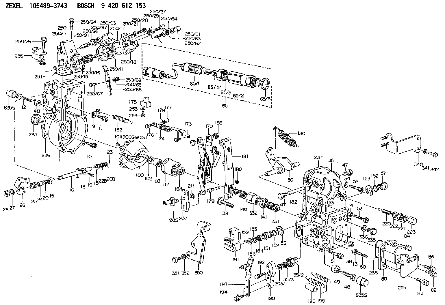
Information governor
BOSCH
9 420 612 153
9420612153
ZEXEL
105489-3743
1054893743
HINO
223005050A
223005050a

Rating:
Scheme ###:
| 1. | [1] | 154004-6420 | GOVERNOR HOUSING |
| 9. | [1] | 154350-6000 | PLATE |
| 10. | [4] | 139006-4100 | BLEEDER SCREW |
| 11. | [4] | 139006-5800 | BLEEDER SCREW |
| 12. | [1] | 154010-7200 | BLEEDER SCREW M8P1.25L62 |
| 13. | [1] | 013020-6040 | UNION NUT M6P1H5 |
| 14. | [1] | 154011-0100 | HEXAGON NUT |
| 14B. | [1] | 154011-2300 | UNION NUT |
| 15. | [2] | 139608-0000 | PACKING RING |
| 15. | [2] | 139608-0000 | PACKING RING |
| 16. | [1] | 155004-3600 | LEVER SHAFT |
| 18. | [1] | 155003-3400 | CONTROL LEVER |
| 19. | [1] | 155006-0500 | BLEEDER SCREW |
| 20. | [1] | 139308-1500 | PLAIN WASHER D18&8T1.0 |
| 20B. | [1] | 139308-1600 | PLAIN WASHER D18&8T1.5 |
| 22B. | [0] | 029310-8050 | SHIM D13.5&8T0.5 |
| 23. | [1] | 154373-2200 | SAFETY PIN |
| 24. | [1] | 154206-2000 | BUSHING |
| 25. | [1] | 154327-9000 | COILED SPRING |
| 26. | [1] | 154381-2600 | CONTROL LEVER |
| 27. | [1] | 014110-8440 | LOCKING WASHER |
| 28. | [1] | 013020-8040 | UNION NUT M8P1.25H7 |
| 35. | [1] | 154515-4720 | GOVERNOR COVER |
| 35/2. | [1] | 154321-2000 | BUSHING |
| 35/3. | [1] | 029621-0080 | PACKING RING |
| 38. | [1] | 154031-3401 | FLAT-HEAD SCREW |
| 39. | [1] | 029201-0160 | UNION NUT |
| 47. | [2] | 154036-1800 | CAPSULE |
| 47. | [2] | 154036-1800 | CAPSULE |
| 48. | [1] | 154010-7700 | BLEEDER SCREW M10P1.25L51 |
| 48B. | [1] | 154010-6000 | BLEEDER SCREW M10P1.25L55 |
| 49. | [1] | 154011-2200 | UNION NUT |
| 50. | [1] | 155615-2300 | FLAT-HEAD SCREW |
| 51. | [5] | 020106-4540 | BLEEDER SCREW M6P1.0L45 |
| 52. | [2] | 029010-6850 | BLEEDER SCREW |
| 53. | [1] | 154010-3100 | BLEEDER SCREW |
| 54. | [2] | 014110-6440 | LOCKING WASHER |
| 65. | [1] | 154610-6520 | RACK SENSOR ASSY |
| 65/1. | [1] | 479742-4120 | RACK SENSOR |
| 65/2. | [1] | 154614-6800 | JOINT CONNECTION |
| 65/3. | [1] | 026524-3040 | GASKET |
| 65/4A. | [0] | 029310-6220 | SHIM D11.5&6.5T0.10 |
| 65/4B. | [0] | 029310-6230 | SHIM D11.5&6.5T0.20 |
| 65/4C. | [0] | 029310-6240 | SHIM D11.5&6.5T0.25 |
| 65/4D. | [0] | 029310-6260 | SHIM D11.5&6.4T1.00 |
| 65/4E. | [0] | 029310-6270 | SHIM D11.5&6.4T1.20 |
| 65/4F. | [0] | 029310-6280 | SHIM D11.5&6.4T1.50 |
| 65/5. | [1] | 154614-1900 | UNION NUT |
| 80. | [1] | 154063-9100 | COVER |
| 82. | [1] | 029020-6210 | BLEEDER SCREW |
| 83. | [1] | 029020-6240 | BLEEDER SCREW |
| 84. | [1] | 020006-1640 | BLEEDER SCREW M6P1L16 4T |
| 86. | [1] | 020006-1840 | BLEEDER SCREW M6P1L18 |
| 100. | [1] | 154100-9320 | FLYWEIGHT ASSEMBLY |
| 101. | [1] | 025803-1610 | WOODRUFF KEY |
| 102. | [1] | 029321-2020 | LOCKING WASHER |
| 103. | [1] | 139212-0000 | UNION NUT |
| 117. | [1] | 154123-2320 | SLIDING PIECE |
| 118/1. | [0] | 029311-0010 | SHIM D14&10.1T0.2 |
| 118/1. | [0] | 029311-0180 | SHIM D14&10.1T0.3 |
| 118/1. | [0] | 029311-0190 | SHIM D14&10.1T0.40 |
| 118/1. | [0] | 029311-0210 | SHIM D14&10.1T1 |
| 118/1. | [0] | 139410-0000 | SHIM D14.0&10.1T0.5 |
| 118/1. | [0] | 139410-0100 | SHIM D14.0&10.1T1.5 |
| 118/1. | [0] | 139410-3000 | SHIM D14&10.1T2.0 |
| 118/1. | [0] | 139410-3100 | SHIM D14&10.1T3.0 |
| 118/1. | [0] | 139410-3200 | SHIM D14&10.1T4.0 |
| 130. | [1] | 154150-7900 | GOVERNOR SPRING |
| 132. | [1] | 154154-0701 | COILED SPRING |
| 140. | [1] | 154183-0020 | HEADLESS SCREW |
| 141. | [1] | 139218-0100 | UNION NUT |
| 150. | [1] | 154200-5601 | SWIVELLING LEVER |
| 151. | [1] | 154200-5501 | BUSHING |
| 152. | [2] | 139700-0000 | O-RING |
| 152. | [2] | 139700-0000 | O-RING |
| 153. | [2] | 154354-3900 | LOCKING WASHER |
| 153. | [2] | 154354-3900 | LOCKING WASHER |
| 154. | [1] | 139610-0101 | PACKING RING |
| 155. | [1] | 139411-0100 | SHIM D22.0&12.0T0.40 |
| 156. | [0] | 139411-0200 | SHIM D18.0&12.0T0.10 |
| 156B. | [0] | 139411-0300 | SHIM D18.0&12.0T0.20 |
| 156C. | [0] | 139411-0400 | SHIM D18.0&12.0T0.30 |
| 157. | [1] | 154204-3500 | BUSHING |
| 159. | [1] | 025803-1310 | WOODRUFF KEY |
| 170. | [1] | 154217-9020 | FORK LEVER |
| 173. | [1] | 016010-0540 | LOCKING WASHER |
| 174. | [1] | 154234-2220 | STRAP |
| 175. | [1] | 154232-1923 | CONNECTOR |
| 176. | [1] | 154222-4900 | BEARING PIN |
| 177. | [1] | 155402-3800 | SAFETY PIN |
| 178. | [1] | 029310-5170 | SHIM D8&5.3T0.5 |
| 179. | [1] | 154238-0701 | BEARING PIN |
| 180. | [1] | 016010-0540 | LOCKING WASHER |
| 181. | [1] | 154239-1120 | TENSIONING LEVER |
| 182. | [1] | 154237-1200 | BEARING PIN |
| 183. | [2] | 154237-1800 | BUSHING |
| 190. | [1] | 154360-2700 | CONTROL LEVER |
| 191. | [1] | 154340-4520 | CONTROL LEVER |
| 192. | [1] | 020006-1670 | BLEEDER SCREW M6P1L16 7T |
| 193. | [1] | 154385-9520 | CONTROL LEVER |
| 194. | [2] | 020006-1240 | BLEEDER SCREW M6P1L12 4T |
| 195. | [2] | 154332-7400 | COILED SPRING |
| 196. | [2] | 154156-2800 | TUBE |
| 203/1. | [0] | 029311-0640 | SHIM D26.0&10.2T0.95 |
| 203/1. | [0] | 029311-0650 | SHIM D26.0&10.2T0.20 |
| 203/1. | [0] | 029311-0660 | SHIM D26.0&10.2T0.25 |
| 203/1. | [0] | 029311-0670 | SHIM D26.0&10.2T0.30 |
| 203/1. | [0] | 029311-0680 | SHIM D26.0&10.2T0.35 |
| 203/1. | [0] | 029311-0690 | SHIM D26.0&10.2T0.40 |
| 203/1. | [0] | 029311-0700 | SHIM D26.0&10.2T0.50 |
| 203/1. | [0] | 139410-1400 | SHIM D26&10.2T0.7 |
| 203/1. | [0] | 139410-1500 | SHIM D26&10.2T0.9 |
| 203/1. | [0] | 139410-1600 | SHIM D26&10.2T0.8 |
| 203/1. | [0] | 139410-2700 | SHIM D26&10.2T0.6 |
| 205. | [1] | 154324-3600 | LEVER SHAFT |
| 207. | [1] | 154326-8220 | CONTROL LEVER |
| 211. | [1] | 016010-0840 | LOCKING WASHER |
| 220. | [1] | 154050-8620 | HEADLESS SCREW |
| 221. | [1] | 029201-2140 | UNION NUT |
| 222. | [2] | 026512-1540 | GASKET D15.4&12.2T1.50 |
| 223. | [1] | 154159-1200 | CAP NUT |
| 235. | [1] | 155412-5300 | IMPELLER WHEEL |
| 236. | [1] | 154413-2900 | GASKET |
| 237. | [1] | 154390-0200 | GASKET |
| 238. | [1] | 139700-0100 | O-RING |
| 250. | [1] | 154420-2320 | MANIFOLD-PRESSURE COMP. |
| 250/1. | [1] | 154415-0320 | DIAPHRAGM HOUSING |
| 250/11. | [1] | 154412-6522 | DIAPHRAGM |
| 250/15. | [1] | 154412-7700 | BUSHING |
| 250/16. | [1] | 154411-5300 | COILED SPRING |
| 250/17. | [2] | 154413-2600 | GASKET |
| 250/18. | [1] | 154404-5000 | COVER |
| 250/20. | [3] | 139006-0900 | BLEEDER SCREW |
| 250/21. | [3] | 014110-6440 | LOCKING WASHER |
| 250/24. | [2] | 020106-1640 | BLEEDER SCREW M6P1.0L14 |
| 250/26. | [2] | 020106-2040 | BLEEDER SCREW M6P1L20 |
| 250/27. | [1] | 029731-0180 | EYE BOLT |
| 250/28. | [2] | 026510-1340 | GASKET D13.4&10.2T1 |
| 250/61. | [1] | 154035-1600 | CAP NUT |
| 250/62. | [1] | 154404-4400 | FLAT-HEAD SCREW |
| 250/63. | [1] | 013030-6040 | UNION NUT M6P1H3.6 |
| 250/64. | [2] | 026506-1040 | GASKET D9.9&6.2T1 |
| 250/66. | [1] | 154412-4622 | CONTROL LEVER |
| 250/67. | [1] | 154412-1600 | BEARING PIN |
| 250/68. | [1] | 029310-5090 | SHIM D10&5.1T0.5 |
| 250/69. | [1] | 016010-0540 | LOCKING WASHER |
| 250/91. | [1] | 154412-5120 | HEADLESS SCREW |
| 250/92. | [1] | 029201-2030 | UNION NUT M12P1.0H4 |
| 250/93. | [1] | 154412-5300 | CAP NUT |
| 250/97. | [2] | 026512-1540 | GASKET D15.4&12.2T1.50 |
| 251. | [1] | 154358-2500 | SEAL RING |
| 253. | [1] | 029320-5020 | LOCKING WASHER |
| 254. | [1] | 010535-1040 | FLAT-HEAD SCREW M5P0.8L10 |
| 255. | [1] | 154373-6120 | BRACKET |
| 256. | [1] | 154373-7120 | BRACKET |
| 331. | [1] | 154179-1720 | HEADLESS SCREW |
| 332. | [1] | 139218-0500 | UNION NUT |
| 335. | [1] | 154352-2600 | CAPSULE |
| 336. | [1] | 029331-6030 | GASKET |
| 340. | [1] | 154372-7820 | BRACKET |
| 341. | [2] | 014110-8440 | LOCKING WASHER |
| 342. | [2] | 010038-1240 | BLEEDER SCREW |
| 350. | [1] | 154372-9500 | BRACKET |
| 351. | [2] | 010010-1640 | BLEEDER SCREW M10P1.5L16 4T |
| 352. | [2] | 014111-0440 | LOCKING WASHER |
Include in #1:
108622-3123
as GOVERNOR
Cross reference number
Zexel num
Bosch num
Firm num
Name
Information:
Caterpillar does not recommend checking actual engine bearing clearances, particularly on small engines, because of the possibility of obtaining inaccurate results, and the possibility of damaging the bearing or journal surfaces. Each Caterpillar engine bearing is quality checked for specific wall thickness. If the crankshaft journals and bores for the block and rods were measured at disassembly and found to be within specifications, no further checks are necessary when using the correct bearings. However, if the serviceman still wants to measure the bearing clearances, Plastigage is an acceptable method. Plastigage is less accurate on small diameter journals where clearances are less than 0.10 mm (0.004 in).
Lead wire, shim stock or a dial bore gauge can damage the bearing surfaces.
1. The serviceman must be very careful to use Plastigage correctly. The following points must be remembered: a. Be sure that the backs of the bearings and the bores are clean and dry.b. Be sure that the bearing locking tabs are properly seated in their studs.c. The crankshaft must be free of oil where the Plastigage touches it.d. If the main bearing clearances are checked with the engine upright or on its side, the crankshaft must be supported. Use a jack under an adjacent crankshaft counterweight and hold the crankshaft against the crown of the bearing. If the crankshaft is not supported, the weight of the crankshaft will cause incorrect readings.e. Put a piece of Plastigage on the crown of the bearing half that is in the cap. Do not allow the Plastigage to extend over the edge of the bearing.f. Install the bearing cap using the correct torque turn specifications. Do not use an impact wrench. Be careful not to dislodge the bearing when the cap is installed.g. Do not run the crankshaft with the Plastigage installed. h. Carefully remove the cap but do not remove the Plastigage. Measure the width of the Plastigage while it is in the bearing cap or on the crankshaft journal, see photograph.i. Remove all the Plastigage before reinstalling the cap. When using Plastigage, the readings can sometimes be unclear. For example, all parts of the Plastigage are not the same width. Measure the major width to be sure they are width the specification range.