Information governor
BOSCH
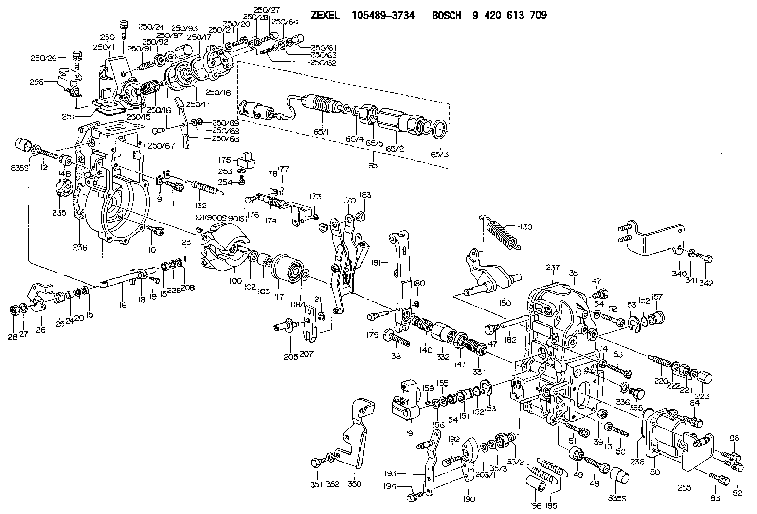
9 420 613 709
9420613709
ZEXEL
105489-3734
1054893734
Rating:
Scheme ###:
| 1. | [1] | 154004-6420 | GOVERNOR HOUSING |
| 9. | [1] | 154350-6000 | PLATE |
| 10. | [4] | 139006-4100 | BLEEDER SCREW |
| 11. | [4] | 139006-5800 | BLEEDER SCREW |
| 12. | [1] | 154010-7200 | BLEEDER SCREW M8P1.25L62 |
| 13. | [1] | 013020-6040 | UNION NUT M6P1H5 |
| 14. | [1] | 154011-0100 | HEXAGON NUT |
| 14B. | [1] | 154011-2300 | UNION NUT |
| 15. | [2] | 139608-0000 | PACKING RING |
| 15. | [2] | 139608-0000 | PACKING RING |
| 16. | [1] | 155004-3600 | LEVER SHAFT |
| 18. | [1] | 155003-3400 | CONTROL LEVER |
| 19. | [1] | 155006-0500 | BLEEDER SCREW |
| 20. | [1] | 139308-1500 | PLAIN WASHER D18&8T1.0 |
| 20B. | [1] | 139308-1600 | PLAIN WASHER D18&8T1.5 |
| 22B. | [0] | 029310-8050 | SHIM D13.5&8T0.5 |
| 23. | [1] | 154373-2200 | SAFETY PIN |
| 24. | [1] | 154206-2000 | BUSHING |
| 25. | [1] | 154327-9000 | COILED SPRING |
| 26. | [1] | 154381-2600 | CONTROL LEVER |
| 27. | [1] | 014110-8440 | LOCKING WASHER |
| 28. | [1] | 013020-8040 | UNION NUT M8P1.25H7 |
| 35. | [1] | 154515-4720 | GOVERNOR COVER |
| 35/2. | [1] | 154321-2000 | BUSHING |
| 35/3. | [1] | 029621-0080 | PACKING RING |
| 38. | [1] | 154031-3401 | FLAT-HEAD SCREW |
| 39. | [1] | 029201-0160 | UNION NUT |
| 47. | [2] | 154036-1800 | CAPSULE |
| 47. | [2] | 154036-1800 | CAPSULE |
| 48. | [1] | 154010-7700 | BLEEDER SCREW M10P1.25L51 |
| 48B. | [1] | 154010-6000 | BLEEDER SCREW M10P1.25L55 |
| 49. | [1] | 154011-2200 | UNION NUT |
| 50. | [1] | 155615-2300 | FLAT-HEAD SCREW |
| 51. | [5] | 020106-4540 | BLEEDER SCREW M6P1.0L45 |
| 52. | [2] | 029010-6850 | BLEEDER SCREW |
| 53. | [1] | 154010-3100 | BLEEDER SCREW |
| 54. | [2] | 014110-6440 | LOCKING WASHER |
| 65. | [1] | 154610-6520 | RACK SENSOR ASSY |
| 65/1. | [1] | 479742-4120 | RACK SENSOR |
| 65/2. | [1] | 154614-6800 | JOINT CONNECTION |
| 65/3. | [1] | 026524-3040 | GASKET |
| 65/4A. | [0] | 029310-6220 | SHIM D11.5&6.5T0.10 |
| 65/4B. | [0] | 029310-6230 | SHIM D11.5&6.5T0.20 |
| 65/4C. | [0] | 029310-6240 | SHIM D11.5&6.5T0.25 |
| 65/4D. | [0] | 029310-6260 | SHIM D11.5&6.4T1.00 |
| 65/4E. | [0] | 029310-6270 | SHIM D11.5&6.4T1.20 |
| 65/4F. | [0] | 029310-6280 | SHIM D11.5&6.4T1.50 |
| 65/5. | [1] | 154614-1900 | UNION NUT |
| 80. | [1] | 154063-9100 | COVER |
| 82. | [1] | 029020-6210 | BLEEDER SCREW |
| 83. | [1] | 029020-6240 | BLEEDER SCREW |
| 84. | [1] | 020006-1640 | BLEEDER SCREW M6P1L16 4T |
| 86. | [1] | 020006-1840 | BLEEDER SCREW M6P1L18 |
| 100. | [1] | 154100-9320 | FLYWEIGHT ASSEMBLY |
| 101. | [1] | 025803-1310 | WOODRUFF KEY |
| 102. | [1] | 029321-2020 | LOCKING WASHER |
| 103. | [1] | 139212-0000 | UNION NUT |
| 117. | [1] | 154123-2320 | SLIDING PIECE |
| 118/1. | [0] | 029311-0010 | SHIM D14&10.1T0.2 |
| 118/1. | [0] | 029311-0180 | SHIM D14&10.1T0.3 |
| 118/1. | [0] | 029311-0190 | SHIM D14&10.1T0.40 |
| 118/1. | [0] | 029311-0210 | SHIM D14&10.1T1 |
| 118/1. | [0] | 139410-0000 | SHIM D14.0&10.1T0.5 |
| 118/1. | [0] | 139410-0100 | SHIM D14.0&10.1T1.5 |
| 118/1. | [0] | 139410-3000 | SHIM D14&10.1T2.0 |
| 118/1. | [0] | 139410-3100 | SHIM D14&10.1T3.0 |
| 118/1. | [0] | 139410-3200 | SHIM D14&10.1T4.0 |
| 130. | [1] | 154150-7900 | GOVERNOR SPRING |
| 132. | [1] | 154154-0701 | COILED SPRING |
| 140. | [1] | 154183-0020 | HEADLESS SCREW |
| 141. | [1] | 139218-0100 | UNION NUT |
| 150. | [1] | 154200-5601 | SWIVELLING LEVER |
| 151. | [1] | 154200-5501 | BUSHING |
| 152. | [2] | 139700-0000 | O-RING |
| 152. | [2] | 139700-0000 | O-RING |
| 153. | [2] | 154354-3900 | LOCKING WASHER |
| 153. | [2] | 154354-3900 | LOCKING WASHER |
| 154. | [1] | 139610-0101 | PACKING RING |
| 155. | [1] | 139411-0100 | SHIM D22.0&12.0T0.40 |
| 156. | [0] | 139411-0200 | SHIM D18.0&12.0T0.10 |
| 156B. | [0] | 139411-0300 | SHIM D18.0&12.0T0.20 |
| 156C. | [0] | 139411-0400 | SHIM D18.0&12.0T0.30 |
| 157. | [1] | 154204-3500 | BUSHING |
| 159. | [1] | 025803-1310 | WOODRUFF KEY |
| 170. | [1] | 154217-9020 | FORK LEVER |
| 173. | [1] | 016010-0540 | LOCKING WASHER |
| 174. | [1] | 154230-9220 | STRAP |
| 175. | [1] | 154232-1923 | CONNECTOR |
| 176. | [1] | 154222-4900 | BEARING PIN |
| 177. | [1] | 155402-3800 | SAFETY PIN |
| 178. | [1] | 029310-5170 | SHIM D8&5.3T0.5 |
| 179. | [1] | 154238-0701 | BEARING PIN |
| 180. | [1] | 016010-0540 | LOCKING WASHER |
| 181. | [1] | 154239-1120 | TENSIONING LEVER |
| 182. | [1] | 154237-1200 | BEARING PIN |
| 183. | [2] | 154237-1800 | BUSHING |
| 190. | [1] | 154360-2700 | CONTROL LEVER |
| 191. | [1] | 154340-4520 | CONTROL LEVER |
| 192. | [1] | 020006-1670 | BLEEDER SCREW M6P1L16 7T |
| 193. | [1] | 154385-9520 | CONTROL LEVER |
| 194. | [2] | 020006-1240 | BLEEDER SCREW M6P1L12 4T |
| 195. | [2] | 154332-9400 | COILED SPRING |
| 196. | [2] | 154156-2800 | TUBE |
| 203/1. | [0] | 029311-0640 | SHIM D26.0&10.2T0.95 |
| 203/1. | [0] | 029311-0650 | SHIM D26.0&10.2T0.20 |
| 203/1. | [0] | 029311-0660 | SHIM D26.0&10.2T0.25 |
| 203/1. | [0] | 029311-0670 | SHIM D26.0&10.2T0.30 |
| 203/1. | [0] | 029311-0680 | SHIM D26.0&10.2T0.35 |
| 203/1. | [0] | 029311-0690 | SHIM D26.0&10.2T0.40 |
| 203/1. | [0] | 029311-0700 | SHIM D26.0&10.2T0.50 |
| 203/1. | [0] | 139410-1400 | SHIM D26&10.2T0.7 |
| 203/1. | [0] | 139410-1500 | SHIM D26&10.2T0.9 |
| 203/1. | [0] | 139410-1600 | SHIM D26&10.2T0.8 |
| 203/1. | [0] | 139410-2700 | SHIM D26&10.2T0.6 |
| 205. | [1] | 154324-3600 | LEVER SHAFT |
| 207. | [1] | 154326-8220 | CONTROL LEVER |
| 211. | [1] | 016010-0840 | LOCKING WASHER |
| 220. | [1] | 154050-8620 | HEADLESS SCREW |
| 221. | [1] | 029201-2140 | UNION NUT |
| 222. | [2] | 026512-1540 | GASKET D15.4&12.2T1.50 |
| 223. | [1] | 154159-1200 | CAP NUT |
| 235. | [1] | 155412-5300 | IMPELLER WHEEL |
| 236. | [1] | 154413-2900 | GASKET |
| 237. | [1] | 154390-0200 | GASKET |
| 238. | [1] | 139700-0100 | O-RING |
| 250. | [1] | 154420-2320 | MANIFOLD-PRESSURE COMP. |
| 250/1. | [1] | 154415-0320 | DIAPHRAGM HOUSING |
| 250/11. | [1] | 154412-6522 | DIAPHRAGM |
| 250/15. | [1] | 154412-7700 | BUSHING |
| 250/16. | [1] | 154411-5300 | COILED SPRING |
| 250/17. | [2] | 154413-2600 | GASKET |
| 250/18. | [1] | 154404-5000 | COVER |
| 250/20. | [3] | 139006-0900 | BLEEDER SCREW |
| 250/21. | [3] | 014110-6440 | LOCKING WASHER |
| 250/24. | [2] | 020106-1640 | BLEEDER SCREW M6P1.0L14 |
| 250/26. | [2] | 020106-2040 | BLEEDER SCREW M6P1L20 |
| 250/27. | [1] | 029731-0180 | EYE BOLT |
| 250/28. | [2] | 026510-1340 | GASKET D13.4&10.2T1 |
| 250/61. | [1] | 154035-1600 | CAP NUT |
| 250/62. | [1] | 154404-4400 | FLAT-HEAD SCREW |
| 250/63. | [1] | 013030-6040 | UNION NUT M6P1H3.6 |
| 250/64. | [2] | 026506-1040 | GASKET D9.9&6.2T1 |
| 250/66. | [1] | 154412-4622 | CONTROL LEVER |
| 250/67. | [1] | 154412-1600 | BEARING PIN |
| 250/68. | [1] | 029310-5090 | SHIM D10&5.1T0.5 |
| 250/69. | [1] | 016010-0540 | LOCKING WASHER |
| 250/91. | [1] | 154412-5120 | HEADLESS SCREW |
| 250/92. | [1] | 029201-2030 | UNION NUT M12P1.0H4 |
| 250/93. | [1] | 154412-5300 | CAP NUT |
| 250/97. | [2] | 026512-1540 | GASKET D15.4&12.2T1.50 |
| 251. | [1] | 154358-2500 | SEAL RING |
| 253. | [1] | 029320-5020 | LOCKING WASHER |
| 254. | [1] | 010535-1040 | FLAT-HEAD SCREW M5P0.8L10 |
| 255. | [1] | 154373-6120 | BRACKET |
| 256. | [1] | 154373-7120 | BRACKET |
| 331. | [1] | 154179-3321 | HEADLESS SCREW |
| 332. | [1] | 139218-0500 | UNION NUT |
| 335. | [1] | 154352-2600 | CAPSULE |
| 336. | [1] | 029331-6030 | GASKET |
| 340. | [1] | 154372-7820 | BRACKET |
| 341. | [2] | 014110-8440 | LOCKING WASHER |
| 342. | [2] | 010038-1240 | BLEEDER SCREW |
| 350. | [1] | 154372-9500 | BRACKET |
| 351. | [2] | 010010-1640 | BLEEDER SCREW M10P1.5L16 4T |
| 352. | [2] | 014111-0440 | LOCKING WASHER |
| 900S. | [1] | 025803-1310 | WOODRUFF KEY |
| 901S. | [1] | 025803-1610 | WOODRUFF KEY |
Include in #1:
108622-3115
as GOVERNOR
Cross reference number
Zexel num
Bosch num
Firm num
Name
Information:
1. Disconnect wires (1) from the Jake Brake. Remove three bolts (2) and two nuts (3). Remove the Jake Brake. 2. Remove the Jake Brake exhaust bridge assemblies (4). The following steps are for the installation of the Jake Brake.3. Put Jake Brake exhaust bridge assemblies (4) in the same positions shown in Photo C52074P1.4. Position the Jake Brake assembly, and install three bolts (2) and two nuts (3) that hold it. Tighten three bolts (2) to a torque of 55 10 N m (41 7 lb ft). Tighten two nuts (3) to a torque of 80 15 N m (59 11 lb ft).5. Connect wires (1) to the Jake Brake.End By:a. install valve cover assembliesDisassemble & Assemble Jake Brake
Start By:a. remove Jake Brake (An Attachment) 1. Apply finger pressure to control valve cover (6). Remove retaining ring (7). Release finger pressure slowly. Remove control valve cover (6), insert (5), spring (4), spring (3), collar (2) and control valve (1). 2. Remove solenoid (8). Remove three O-ring seals (9) from the solenoid. 3. Remove locknut (11). Back out adjusting screw (10) until the slave piston is fully retracted. 4. Using a suitable size clamp, compress retainer (15) until it is 1mm (.039 in) below the retaining ring groove. Using suitable size snap ring pliers, remove retaining ring (16). Slowly loosen the clamp to release the spring pressure against retainer (15), springs (14) and (13) and slave piston (12). 5. Using suitable snap ring pliers, remove retaining ring (20). Remove retainer (19), spring (18) and master piston assembly (17). The following steps are for the assembly of the Jake Brake.6. Check the condition of the master piston assembly (17). The master piston assembly must be free of score and wear marks.7. Install master piston assembly (17), spring (18), retainer (19) and retaining ring (20).8. Install slave piston (12), springs (13) and (14) and retainer (15). Clamp and compress and slave piston retainer until it is 1 mm (.039 in) below the retaining ring groove. Install retaining ring (16). Release the clamp. Be sure retainer (15) is seated properly.9. Screw adjusting screw (10) in until it makes contact with the slave piston. Install locknut (11) on the screw.
Be sure O-ring seals (9) are seated on solenoid (8). Do not twist or unseat the O-ring seals during installation of the solenoid.
10. Check the condition of the O-ring seals (9) used on solenoid (8). If the seals are worn or damaged, use new parts for replacement. Install three O-ring seals (9) on solenoid valve (8). Install solenoid valve (8), and tighten it to a torque of 7 N m (60 lb in).11. Install control valve (1). Install collar (2) with the longer sleeve area facing up. Install springs (3) and (4) and insert (5). Install control valve cover (6). Install retaining ring (7). Rotate the retaining ring so the retaining ring ears are located away from the slot in the housing. Release finger pressure. For assembly adjustments of