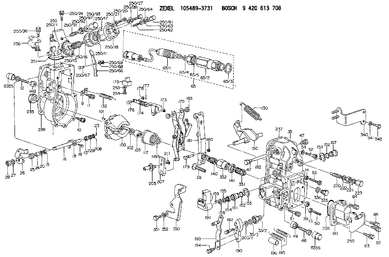
Information governor
BOSCH
9 420 613 708
9420613708
ZEXEL
105489-3731
1054893731
Rating:
Scheme ###:
| 1. | [1] | 154004-6420 | GOVERNOR HOUSING |
| 9. | [1] | 154350-6000 | PLATE |
| 10. | [4] | 139006-4100 | BLEEDER SCREW |
| 11. | [4] | 139006-5800 | BLEEDER SCREW |
| 12. | [1] | 154010-7200 | BLEEDER SCREW M8P1.25L62 |
| 13. | [1] | 013020-6040 | UNION NUT M6P1H5 |
| 14. | [1] | 154011-0100 | HEXAGON NUT |
| 14B. | [1] | 154011-2300 | UNION NUT |
| 15. | [2] | 029620-8050 | PACKING RING |
| 15. | [2] | 029620-8050 | PACKING RING |
| 16. | [1] | 155004-3600 | LEVER SHAFT |
| 18. | [1] | 155003-3400 | CONTROL LEVER |
| 19. | [1] | 155006-0500 | BLEEDER SCREW |
| 20. | [1] | 139308-1500 | PLAIN WASHER D18&8T1.0 |
| 20B. | [1] | 139308-1600 | PLAIN WASHER D18&8T1.5 |
| 22B. | [0] | 029310-8050 | SHIM D13.5&8T0.5 |
| 23. | [1] | 154373-2200 | SAFETY PIN |
| 24. | [1] | 154206-2000 | BUSHING |
| 25. | [1] | 154327-9000 | COILED SPRING |
| 26. | [1] | 154381-2600 | CONTROL LEVER |
| 27. | [1] | 014110-8440 | LOCKING WASHER |
| 28. | [1] | 013020-8040 | UNION NUT M8P1.25H7 |
| 35. | [1] | 154515-4720 | GOVERNOR COVER |
| 35/2. | [1] | 154321-2000 | BUSHING |
| 35/3. | [1] | 029621-0080 | PACKING RING |
| 38. | [1] | 154031-3401 | FLAT-HEAD SCREW |
| 39. | [1] | 029201-0160 | UNION NUT |
| 47. | [2] | 154036-1800 | CAPSULE |
| 47. | [2] | 154036-1800 | CAPSULE |
| 48. | [1] | 154012-5100 | BLEEDER SCREW |
| 48B. | [1] | 154012-4800 | BLEEDER SCREW M10P1.25L51 |
| 49. | [1] | 154011-2200 | UNION NUT |
| 50. | [1] | 155615-2300 | FLAT-HEAD SCREW |
| 51. | [5] | 020106-4540 | BLEEDER SCREW M6P1.0L45 |
| 52. | [2] | 029010-6850 | BLEEDER SCREW |
| 53. | [1] | 154010-3100 | BLEEDER SCREW |
| 54. | [2] | 014110-6440 | LOCKING WASHER |
| 65. | [1] | 154610-6120 | RACK SENSOR ASSY |
| 65/1. | [1] | 479742-3620 | RACK SENSOR |
| 65/2. | [1] | 154614-4900 | JOINT CONNECTION |
| 65/3. | [1] | 026524-3040 | GASKET |
| 65/4A. | [0] | 029310-6220 | SHIM D11.5&6.5T0.10 |
| 65/4B. | [0] | 029310-6230 | SHIM D11.5&6.5T0.20 |
| 65/4C. | [0] | 029310-6240 | SHIM D11.5&6.5T0.25 |
| 65/4D. | [0] | 029310-6260 | SHIM D11.5&6.4T1.00 |
| 65/4E. | [0] | 029310-6270 | SHIM D11.5&6.4T1.20 |
| 65/4F. | [0] | 029310-6280 | SHIM D11.5&6.4T1.50 |
| 65/5. | [1] | 154614-1900 | UNION NUT |
| 80. | [1] | 154063-9100 | COVER |
| 82. | [1] | 029020-6210 | BLEEDER SCREW |
| 83. | [1] | 029020-6240 | BLEEDER SCREW |
| 84. | [1] | 020006-1640 | BLEEDER SCREW M6P1L16 4T |
| 86. | [1] | 020006-1840 | BLEEDER SCREW M6P1L18 |
| 100. | [1] | 154100-9320 | FLYWEIGHT ASSEMBLY |
| 101. | [1] | 025803-1610 | WOODRUFF KEY |
| 102. | [1] | 029321-2020 | LOCKING WASHER |
| 103. | [1] | 139212-0000 | UNION NUT |
| 117. | [1] | 154123-2320 | SLIDING PIECE |
| 118/1. | [0] | 029311-0010 | SHIM D14&10.1T0.2 |
| 118/1. | [0] | 029311-0180 | SHIM D14&10.1T0.3 |
| 118/1. | [0] | 029311-0190 | SHIM D14&10.1T0.40 |
| 118/1. | [0] | 029311-0210 | SHIM D14&10.1T1 |
| 118/1. | [0] | 139410-0000 | SHIM D14.0&10.1T0.5 |
| 118/1. | [0] | 139410-0100 | SHIM D14.0&10.1T1.5 |
| 118/1. | [0] | 139410-3000 | SHIM D14&10.1T2.0 |
| 118/1. | [0] | 139410-3100 | SHIM D14&10.1T3.0 |
| 118/1. | [0] | 139410-3200 | SHIM D14&10.1T4.0 |
| 130. | [1] | 154150-7900 | GOVERNOR SPRING |
| 132. | [1] | 154154-0701 | COILED SPRING |
| 140. | [1] | 154183-0020 | HEADLESS SCREW |
| 141. | [1] | 139218-0100 | UNION NUT |
| 150. | [1] | 154200-5601 | SWIVELLING LEVER |
| 151. | [1] | 154200-5501 | BUSHING |
| 152. | [2] | 139700-0000 | O-RING |
| 152. | [2] | 139700-0000 | O-RING |
| 153. | [2] | 154354-3900 | LOCKING WASHER |
| 153. | [2] | 154354-3900 | LOCKING WASHER |
| 154. | [1] | 139610-0101 | PACKING RING |
| 155. | [1] | 139411-0100 | SHIM D22.0&12.0T0.40 |
| 156. | [0] | 139411-0200 | SHIM D18.0&12.0T0.10 |
| 156B. | [0] | 139411-0300 | SHIM D18.0&12.0T0.20 |
| 156C. | [0] | 139411-0400 | SHIM D18.0&12.0T0.30 |
| 157. | [1] | 154204-3500 | BUSHING |
| 159. | [1] | 025803-1310 | WOODRUFF KEY |
| 170. | [1] | 154217-9020 | FORK LEVER |
| 173. | [1] | 016010-0540 | LOCKING WASHER |
| 174. | [1] | 154235-1620 | STRAP |
| 175. | [1] | 154232-1923 | CONNECTOR |
| 176. | [1] | 154222-4900 | BEARING PIN |
| 177. | [1] | 155402-3800 | SAFETY PIN |
| 178. | [1] | 029310-5170 | SHIM D8&5.3T0.5 |
| 179. | [1] | 154238-0701 | BEARING PIN |
| 180. | [1] | 016010-0540 | LOCKING WASHER |
| 181. | [1] | 154239-1120 | TENSIONING LEVER |
| 182. | [1] | 154237-1200 | BEARING PIN |
| 183. | [2] | 154237-1800 | BUSHING |
| 190. | [1] | 154360-2700 | CONTROL LEVER |
| 191. | [1] | 154340-4520 | CONTROL LEVER |
| 192. | [1] | 020006-1670 | BLEEDER SCREW M6P1L16 7T |
| 193. | [1] | 154385-9520 | CONTROL LEVER |
| 194. | [2] | 020006-1240 | BLEEDER SCREW M6P1L12 4T |
| 195. | [2] | 154332-7400 | COILED SPRING |
| 196. | [2] | 154156-2800 | TUBE |
| 203/1. | [0] | 029311-0640 | SHIM D26.0&10.2T0.95 |
| 203/1. | [0] | 029311-0650 | SHIM D26.0&10.2T0.20 |
| 203/1. | [0] | 029311-0660 | SHIM D26.0&10.2T0.25 |
| 203/1. | [0] | 029311-0670 | SHIM D26.0&10.2T0.30 |
| 203/1. | [0] | 029311-0680 | SHIM D26.0&10.2T0.35 |
| 203/1. | [0] | 029311-0690 | SHIM D26.0&10.2T0.40 |
| 203/1. | [0] | 029311-0700 | SHIM D26.0&10.2T0.50 |
| 203/1. | [0] | 139410-1400 | SHIM D26&10.2T0.7 |
| 203/1. | [0] | 139410-1500 | SHIM D26&10.2T0.9 |
| 203/1. | [0] | 139410-1600 | SHIM D26&10.2T0.8 |
| 203/1. | [0] | 139410-2700 | SHIM D26&10.2T0.6 |
| 205. | [1] | 154324-3600 | LEVER SHAFT |
| 207. | [1] | 154326-7420 | CONTROL LEVER |
| 211. | [1] | 016010-0840 | LOCKING WASHER |
| 220. | [1] | 154050-8620 | HEADLESS SCREW |
| 221. | [1] | 029201-2140 | UNION NUT |
| 222. | [2] | 026512-1540 | GASKET D15.4&12.2T1.50 |
| 223. | [1] | 154159-1200 | CAP NUT |
| 235. | [1] | 155412-5300 | IMPELLER WHEEL |
| 236. | [1] | 154390-1500 | GASKET |
| 237. | [1] | 154390-0200 | GASKET |
| 238. | [1] | 139700-0100 | O-RING |
| 250. | [1] | 154420-1620 | MANIFOLD-PRESSURE COMP. |
| 250/1. | [1] | 154415-0320 | DIAPHRAGM HOUSING |
| 250/11. | [1] | 154412-6522 | DIAPHRAGM |
| 250/15. | [1] | 154412-7700 | BUSHING |
| 250/16. | [1] | 154411-3800 | COILED SPRING |
| 250/17. | [2] | 154413-2600 | GASKET |
| 250/18. | [1] | 154404-5000 | COVER |
| 250/20. | [3] | 139006-0900 | BLEEDER SCREW |
| 250/21. | [3] | 014110-6440 | LOCKING WASHER |
| 250/24. | [2] | 020106-1640 | BLEEDER SCREW M6P1.0L14 |
| 250/26. | [2] | 020106-2040 | BLEEDER SCREW M6P1L20 |
| 250/27. | [1] | 029731-0180 | EYE BOLT |
| 250/28. | [2] | 026510-1340 | GASKET D13.4&10.2T1 |
| 250/61. | [1] | 154035-1600 | CAP NUT |
| 250/62. | [1] | 154404-4400 | FLAT-HEAD SCREW |
| 250/63. | [1] | 013030-6040 | UNION NUT M6P1H3.6 |
| 250/64. | [2] | 026506-1040 | GASKET D9.9&6.2T1 |
| 250/66. | [1] | 154412-4622 | CONTROL LEVER |
| 250/67. | [1] | 154412-1600 | BEARING PIN |
| 250/68. | [1] | 029310-5090 | SHIM D10&5.1T0.5 |
| 250/69. | [1] | 016010-0540 | LOCKING WASHER |
| 250/91. | [1] | 154412-5120 | HEADLESS SCREW |
| 250/92. | [1] | 029201-2030 | UNION NUT M12P1.0H4 |
| 250/93. | [1] | 154412-5300 | CAP NUT |
| 250/97. | [2] | 026512-1540 | GASKET D15.4&12.2T1.50 |
| 251. | [1] | 154358-2500 | SEAL RING |
| 253. | [1] | 029320-5020 | LOCKING WASHER |
| 254. | [1] | 010535-1040 | FLAT-HEAD SCREW M5P0.8L10 |
| 255. | [1] | 154373-6120 | BRACKET |
| 256. | [1] | 154373-7120 | BRACKET |
| 331. | [1] | 154179-3321 | HEADLESS SCREW |
| 332. | [1] | 139218-0500 | UNION NUT |
| 335. | [1] | 154352-2600 | CAPSULE |
| 336. | [1] | 029331-6030 | GASKET |
| 340. | [1] | 154372-7820 | BRACKET |
| 341. | [2] | 014110-8440 | LOCKING WASHER |
| 342. | [2] | 010038-1240 | BLEEDER SCREW |
| 350. | [1] | 154372-9500 | BRACKET |
| 351. | [2] | 010010-1640 | BLEEDER SCREW M10P1.5L16 4T |
| 352. | [2] | 014111-0440 | LOCKING WASHER |
Include in #1:
108622-3111
as GOVERNOR
Cross reference number
Zexel num
Bosch num
Firm num
Name
Information:
At operating temperature, the engine cooling system is hot and under pressure. Steam can cause personal injury. Check the coolant level only after the engine has been stopped and the fill cap on the radiator is cool enough to touch with your bare hand. Remove the fill cap slowly to relieve pressure. Cooling system conditioner contains alkali. Avoid contact with skin and eyes to prevent personal injury.
1. Drain the coolant from the cooling system into a suitable container for disposal. 2. Disconnect the water supply hose from the water pump inlet.3. Remove connector pipe (1). Remove two bolts (2) and the washers. Remove oil fill pipe (3).4. Remove bolts and washers (4) and water pump (5) from the front housing. The following steps are for the installation of the water pump.5. Check the condition of the O-ring seal used between the water pump and the front housing. If the seal is worn or damaged, use a new part for replacement. Install the O-ring seal on the water pump.6. Lubricate the bore in the front housing with clean engine oil. Put the water pump in position in the front housing. Install bolts (4) and the washers that hold the water pump. Tighten the bolts evenly.7. Check the condition of the gaskets used with connector pipe (1) and oil fill pipe (3). If the gaskets are worn or damaged, use new parts for replacement.8. Position the gasket and connector pipe (1) on the engine. Install the bolts and washers that hold it.9. Put oil fill pipe (3) in position on the engine. Be sure the gasket is in position between the regulator and oil fill pipe. Install oil fill pipe. Install bolts (2) and the washers.10. Connect the water supply hose to the inlet of the water pump.11. After installation of the alternator, fill the cooling system with coolant to the correct level. See the Operation & Maintenance Manual for the correct filling procedure.End By:a. Install alternator.Disassemble Water Pump
Start By:Remove the water pump. Refer to Disassembly and Assembly, "Water Pump - Remove". The information is in this manual.
Keep all parts clean from contaminants. Contaminants may cause rapid wear and shortened component life
(3) Cover bolts(4) Hex washer(5) Bolt(6) Bearing(7) Gear(8) Retaining ring(9) Impeller(10) Shaft(11) Water seal(12) Oil seal(13) Water pump housing 1. Remove water pump elbow (1). Remove elbow (2). 2. Remove cover bolts (3). Carefully separate the housing from the cover. 3. Hold hex washer (4). Remove hex socket head bolt (5). 4. Remove bearing (6). 5. Use Tooling (A) to remove gear (7). 6. Use Tooling (B) to remove retaining ring (8). Remove inner bearing (6). 7. Use Tooling (C) to remove impeller (9). 8. Use a hydraulic press and remove shaft assembly (10). 9. Remove water seal (11). 10. Remove oil seal (12).Assemble Water Pump
Keep all parts clean from contaminants. Contaminants may cause rapid wear and shortened component life.
(3) Cover bolts(4) Hex washer(5) Bolt(6) Bearing(7) Gear(8) Retaining ring(9) Impeller(10) Shaft(11) Water seal(12) Oil seal(13) Water pump housing1. Use